An Improved Simulator of AC45 Foiling Catamarans for Crew
Training
Filippo Rocchini and Paolo Conti
Department of Engineering, University of Perugia, Via Goffredo Duranti, 93, Perugia, Italy
Keywords: Sailing Simulator, Crew Training, America’s Cup, Real-time Simulator, Human Interface.
Abstract: To-day America's Cup catamarans have many innovative features such as hydrodynamic foils and rigid
wings instead of soft sails. They are designed not only to float but also to heave and "fly" over the sea
surface. These new features require new skills that the crew must acquire. The work presented in the paper
deals with this problem and describes a foiling catamaran simulator designed for training purpose. The
simulator is designed primarily to interact with the in-training team and to feedback the crewmen with
realistic physical reactions in an immersive scenario; secondly the simulator gives the opportunity to
compare different race strategies and to select the most promising one. The main features of the simulator
are illustrated, some graphical evaluations are displayed and results are discussed.
1 INTRODUCTION
The design and construction of high-speed sailing
multihulls is going through a very innovative period.
Since the 2007 America’s Cup, done with
monohulls, a large number of high performance
multihulls have been built. These boats have the
power to attract media interest and a larger
proportion of the general public because of their
speed and athletic skill required by the crew.
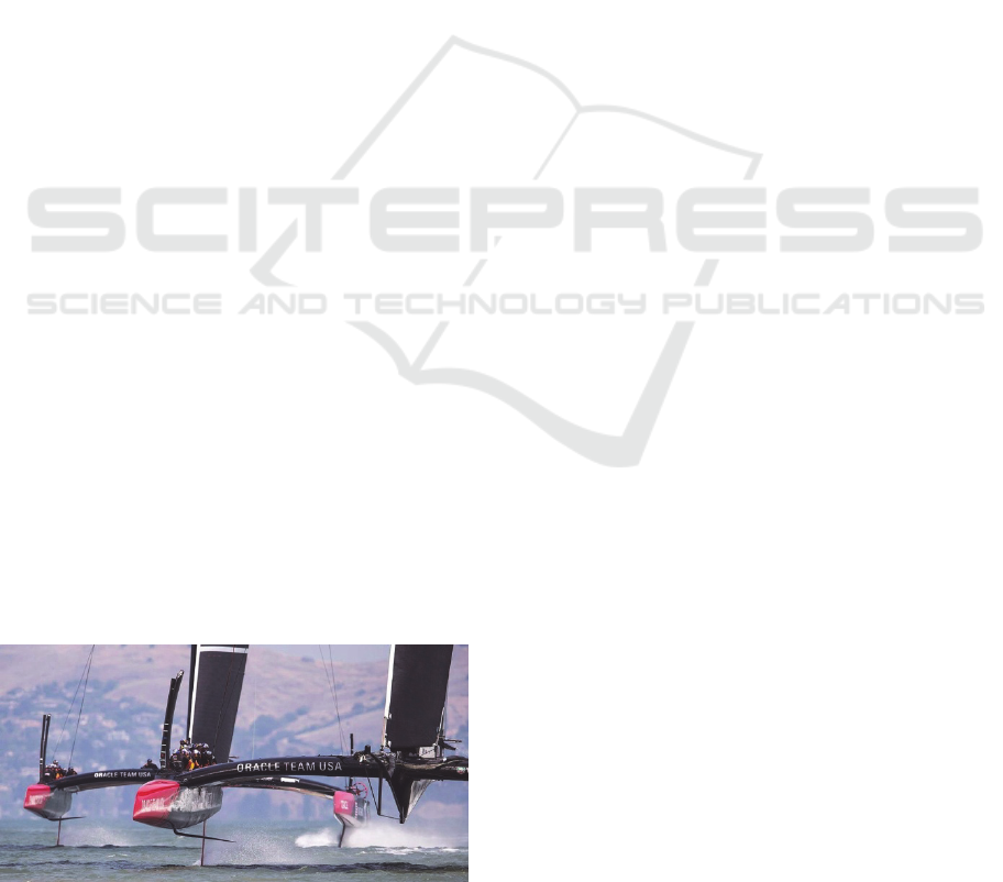
Figure 1: AC72 Oracle Team USA.
Since 2007, one of the most important teams, BMW
Oracle, has developed the 90-foot trimaran that won,
in 2010, one of the strangest America’s Cup ever
raced, due to the presence of one catamaran, with a
classic sail plan, and one trimaran, with a large wing
sail. Following that, after the change of the
America’s Cup rules, a number of AC45 and AC72
class boats have been designed and built. The
September 2013 event in San Francisco Bay, shows
the power of these boats that can be considered as
the Formula 1 of the water. They are large, beautiful,
fast and built with high-tech materials. They have
innovative features such as foils and wings which
make them completely new.
The knowledge of how to handle these boats is
not only important to win the Cup but also to ensure
the safety of the crew. The importance of the latter
topic is paramount, as demonstrated by the Artemis
AC72 capsize, which led to the loss of life of
Olympic sailor Andy Simpson.
These reasons highlight a need for the
formulation of sailing simulators, in order to provide
the Teams with a key tool. It has to be more realistic
as possible and provide a user experience as close as
possible to the reality to allow crew members to
train and know how to handle the boat adapting their
individual, diverse sailing background to the new
boats. These considerations led to the formulation of
an AC45 simulator by University of Southampton
students, (Breschan L.M., Lidtker A., Giovannetti
L.M., Sampson A., Vitti M., 2012/2013.). The scope
of this simulator, however, is limited: only the tack
manoeuvre is taken into account, and the boat cannot
sail in foiling mode. The simulator described in the
present paper was formulated using the
Southampton simulator as a starting point, and
overcomes some of its limitations.
177
Rocchini F. and Conti P..
An Improved Simulator of AC45 Foiling Catamarans for Crew Training.
DOI: 10.5220/0005142401770182
In Proceedings of the 2nd International Congress on Sports Sciences Research and Technology Support (icSPORTS-2014), pages 177-182
ISBN: 978-989-758-057-4
Copyright
c
2014 SCITEPRESS (Science and Technology Publications, Lda.)
2 THE SIMULATOR
The simulator consists of three different parts: the
graphical interface, the mathematical modelling and
the physical interface.
The graphical interface consists of a screen view
of the virtual scene seen from the boat to know the
instantaneous setting of the catamaran. This aspect
was touched only marginally in order to verify the
model's reliability which was developed on the
work.
The mathematical modelling of the AC45
provides the boat’s response to the different
environmental conditions encountered during a race
(aero and hydrodynamic forces) as well as the crew
actions. In this work only these two areas were
considered.
The physical model aims to provide sailors with
a physical reproduction of the catamaran. Using the
results of the mathematical model, it is intended to
give to the crew a more immersive, realistic feel of
the boat and the race scenarios.
3 MATHEMATICAL
MODELLING
3.1 Geometric Characteristics
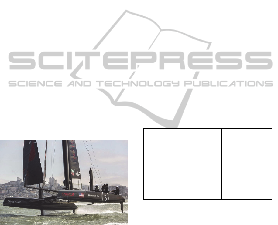
Figure 2: AC45 Oracle team USA with foils.
The model simulates the behaviour of the AC45
catamaran equipped with different appendages in
order to make it able to fly over the water. The main
parameter of the AC45 are available in the official
America’s Cup website but, in order to exactly reply
its behaviour, some parameters - which are not of
public domain - were introduced in the model on the
basis of previous experience on catamarans.
Moreover, in order to implement new characteristics
and to make the simulator able to deal with the new
frontiers of the technology, the capability to lift
over the sea and to "fly" thanks to the foils was
introduced.
These new features of the catamaran make it
incredibly different from a classical catamaran.
When the boat flies, the hull resistance goes to zero
and each variation of the rudders position has a big
effect on the boat heading. The same sensation could
be experienced on fast skiff boats, and this is the
reason why many of the team’s crewmen came from
small dinghy. In this contest, the simulator plays an
important role on adapting the helmsman and the
crew skills to the new boats.
There is a large piece of information in literature
about normal catamarans or multihull boats. In fact,
they are used to complete the round around the
world and to break every year different records
because of their velocity. But the presence of foils is
a new phenomenon appeared during the last
America’s Cup. Before that date, no team had any
experience about it and a massive research effort
was carried on to acquire new experience and
knowledge. Unfortunately all the knowledge
acquired is proprietary of the teams and held
confidential
Table 1: Main boat parameters.
LOA 13,45 m
Bmax 6,77 m
Mastheight 21,50 m
Wingwidth(max) 5,50 m
Upwindsailplane
(wing+headsail)
133 m
2
Downwindsailplane
(wing+gennaker)
210 m
2
3.1.1 Appendages
Surfing on internet, it is possible to see some videos
and pictures that show Oracle team USA and
Artemis team using the L-shape daggerboards and
T-shape rudders. It is easy to see that the shapes
among the two teams are different. Each team tries
to reach the more stable and less resistant
configuration. Another problem influencing
daggerboards shape is that they carry the weight of
the entire boat and the crew and the stresses are high
because of their small cross section. The appendage
shape could suffers also some limitation due the
difficulty to obtain sharp angles with composite
materials. To solve these problems, the designers
icSPORTS2014-InternationalCongressonSportSciencesResearchandTechnologySupport
178

have utilized aerospace technology in composite
elements manufacturing.
The simulator model implements a normal
daggerboard and - in order to give the sideforce
necessary to balance the heeling force - a NACA
0012 shape foil was added at its tip allowing the
boat lift. All the characteristics of this shape were
found on the literature and 3-D effects were added
later (Abbott I.H., von Doenhoff A.E., 1959.). As a
result the two parts of the daggerboard are
considered separately and all the parameters vary
independently from each other .
The other innovation of the 34°th America’s Cup
was the wing sail. It was showed to the big public
during the America’s Cup of 2010, when the Alinghi
catamaran lost the Cup versus the big trimaran of
Oracle which had a huge wing. The AC45 is
characterized by a symmetric wing sail formed by a
main wing rotating about the mast and three rear
flaps distributed spanwise rotating at 90% of the
chord of the forward wing. Due to the symmetry and
the possibility to rotate the four parts, the wing is
able to produce lift in both port and starboard tack.
The structure of the wing is made of a carbon fibre
frame covered with a light soft membrane. The
crew is able to change during the race the sheeting
angle of the main wing, the camber of the whole
wing and the twist of the flaps. The advantage of
the wing respect to a classic soft sail is the
possibility to produce a larger lift due to a absence
of turbulence behind the must yielding a more
uniform and continuous pressure on the sail surface
(Haack N., 2010/11.). Another important feature is
the possibility to have high lift even with low
apparent wind angle . That is very important on high
speed catamaran. In fact, they can reach speed two
times larger than true wind velocity
3.2 Equations
In order to have the possibility to insert the foils and
make the AC45 able to fly, the equations of pitch
and heave were added to the model:
∗
∗
∗
∗
Where "z" reperesants the vertical lift, ω the pitch
rotation and the subscripts "H", "Wi", "A", "HS",
"WS", refer, respectively, to hull, windage,
appendages, headsail and wing sail.
The equations contain all the forces in the
vertical direction and the moments around the pitch
axis acting on the boat. The model has the
possibility to change the setting of the boat taking
into account the actions of the crew trimming, the
position of the headsail, wing and rudder or
modifying the twist of the wing or the flatting of the
headsail. Also the daggerboards position can be
modified as they assume a basic role on the ability
of the crew to complete the manoeuvres. The
America’s Cup showed the importance of fast
sailing with the hull lifted from the sea in order to
maintain constant high speed. The simulator allows
the crew to test all this manoeuvres in an immersive
environment, finding the best solution and acquiring
the skills to beat the other team.
The possibility to jibe without touching the water
was already known. The new challenge is now to
complete also the tack without wetting the hulls. The
team that will obtain this result will probably win the
Cup. The simulator can offer an interesting tool to
improve the catamaran features and the crew skills
(Masuyama Y., Fukasawa, T, 2011).
With the foil the problem of the pitch pole is
damped but still central on the catamarans. When the
boat bears away, the bow is pushed into the water
and the ability of the crew to set off, first all the sails
and then the headsail, is of fundamental importance.
The helmsman as well has to move smoothly the
rudder not to throw out of the boats the crew
members as happened to Dean Barker in the final
race of the Louis Vuitton Cup versus Luna Rossa.
3.3 Forces on the Model
In the sailing boats, there are different forces, which
are due both to aerodynamics and hydrodynamics
components that make the model complex (Keuning
J.A., Sonnenberg U.B, 1998). These two fluids are
very well know and there are many references in
literature; however, the interaction between them
make all the problem more complex and needs to be
simplified. Moreover, the model has to change
depending on the position of the boat. In fact, if the
boat is floating, the hull has a large resistance force
arising from the friction resistance, wave resistance,
induced resistance and heeling resistance. These
components can be evaluated with classical
formulae as presented on the ORC VPP
Documentation (ORC VPP 2012). The innovation of
the new catamarans is the lift forces of the foils.
These are found using the lift coefficients and the
wetted area of the foils.
,
1
2
∗∗
∗
∗
AnImprovedSimulatorofAC45FoilingCatamaransforCrewTraining
179
The area changes with the heave position of the
boat, with a linear reduction when the boat is over
0.5 m whilst the lift coefficient is fixed and changes
with the pitch angle. It is obvious that the ability of
the crew consist of launching the boat as faster as
possible in order to have the maximum lift force and
lift the whole boat over the sea. The ability to have a
smooth variation of heading appears of crucial
importance to keep the boat always fast and lifted
from the water.
3.4 Cues to the User
In order to ensure efficacity and effectivness of the
simulator the cues from the simulator to the users
are extremely important. The crew must be able to
communicate with the simulator and receive the
right feedback from it. The torque on the rudder,
wing or headsail are very important and allow the
sailors to feel the minimum variation of the wind
speed, of its angle of attack of the boat speed.
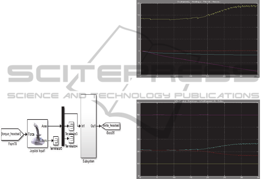
Figure 3: Headsail input and feedback system.
The simulator has three input signals and three
feedback signals, this means that it is intend for
three members crew. They must work together and
interact simultaneously with the simulator. They
must synchronously cooperate to keep the boat
stable. Even if the simulator does not still have a
position sensor, it can be obtained with the
supervision of a coach who can see any error.
The possibility to easily teach the user is the
main advantage of the simulators but a second
capability is represented by the possibility to
compare different race strategies and to select the
most promising one on the basis of weather
forecasting (Scarponi et a. -2006).
The crew can also move and change the
appendages position. As explained above, the
daggerboards position is very important on the
manoeuvres and the possibility to set in or off when
they want, allow them to find the best setting and the
best actions sequences. To see the behaviour of the
catamaran the crew can see through some scope and
have the feedback of their actions.
This solution appear very realistic because in the
last America’s Cup the wear technologies were
massively used all the crew components could see
instantly the parameters of their interest.
Figure 4: Time histories of boat main parameters: Boat
Speed, Yellow – Heave, Red – Pitch, Blue – Heel, Purple.
Figure 5: Time histories of true and apparent wind: True
Wind Angle, Purple – True Wind Speed, Yellow –
Apparent Wind Angle, Red – Apparent Wind Speed, Blue.
4 RESULTS
The validation of the simulation was demonstrated
by a critical evaluation of its results and some tests.
In should be borne in mind that a comparison with
results from other simulators is not possible because
no other foiling AC45 simulators are available to
date. This shows the difficulty in working to this
project but also the importance of the challanging
task. The results given below show that the
simulator’s behaviour is in agreement with that of
the actual boat. All the main parameters, such as
pitch and heave, are consistent with those observed
on real boats.
icSPORTS2014-InternationalCongressonSportSciencesResearchandTechnologySupport
180
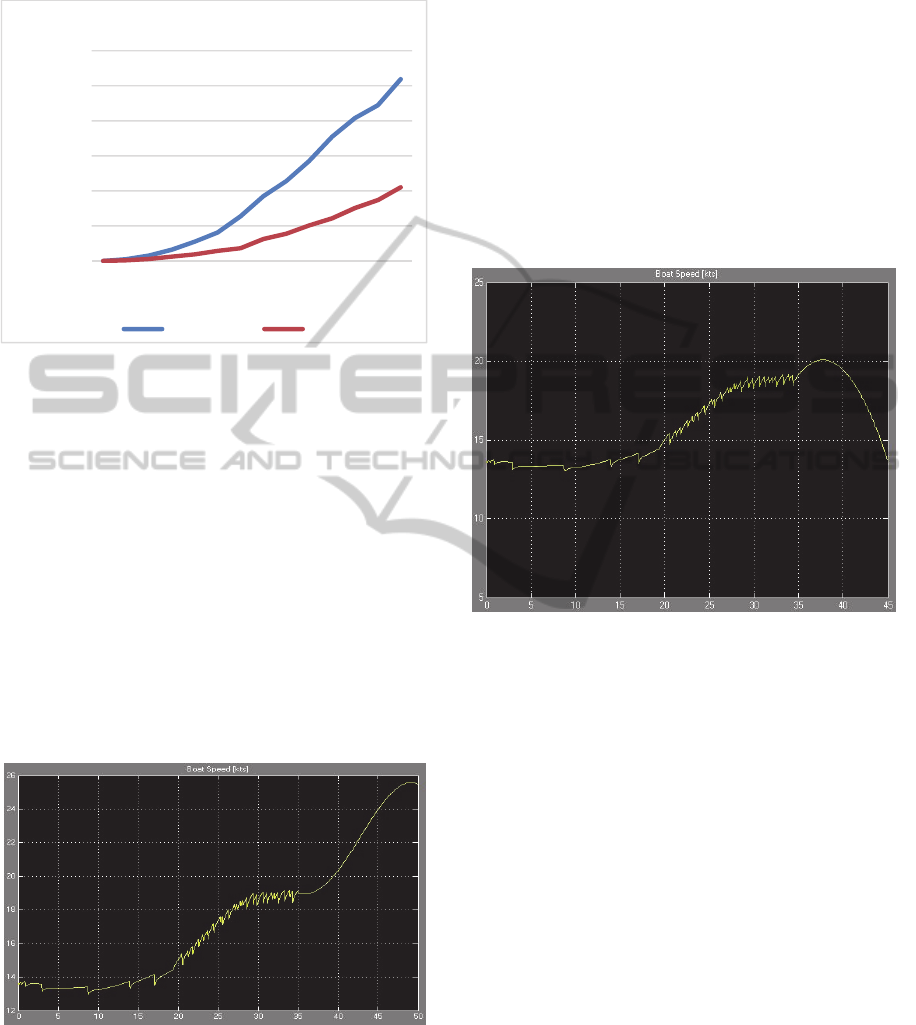
4.1 Total Resistance
Figure 6: Resistance graph.
The graph above compares the total resistance when
the boat sails in the water and when it is flying. It
has to be read considering that until the boat speed is
below 10 kts, the catamaran has all the hull
resistance (blue line). Above that velocity, the
catamaran starts foiling: the hull resistance drops to
zero and the appendages’ resistance and windage
resistance (orange line) are the only resistance
components left.
4.2 Bear Away
The behaviour of the simulator to the changing of
direction is important in order to capture the
catamaran’s motion.
Figure 7: Time history of boat speed [kts] when bearing
away at the upwind mark.
The boat speed on this manoeuvre increases when
the helmsman starts to bear away (35
th
sec.). It
means that the mathematical model predicts
correctly the acceleration of the boat when it bears
away at the upwind mark. The Pitch angle starts to
increase and finds a new equilibrium position with
the bow closer to the water.
4.3 Luff up
Also on the luff up the results given by the
mathematical model are consistent with sailing
experience and the expected behaviour of a foiling
multihull. At first the speed increases marginally and
then, when the apparent wind angle drops, the
catamaran slows down because of the reduction of
the sail forces.
Figure 8: Time history of boat speed [kts] when luffing up.
4.4 Graphical Interface
The simulator has a graphical interface to display to
the crew the boat position and the movements of the
boat. The present implementation is a preliminary
version developed at Southampton University
(Breschan et a., 2012/2013). In order to take full
advantage of the simulator the graphical interface
must be upgraded and more details must be
introduce to yield a full immersive environment. Up
to now, the existing version is linked with the
simulator and give an essential visual feedback.
5 CONCLUSIONS AND FURTHER
WORK
The introduction on the simulator of the two more
degrees of freedom (pitch and lift) gave the
possibility to add the foils at the catamaran. In that
way, it was possible to verify the reliability of the
mathematical model and to provide the in-training
0
1000
2000
3000
4000
5000
6000
0 2 4 6 8 10 12 14 16 18 20 22 24 26
Resistance[N]
Boatspeed[kts]
Totalresistance
heave0m heave1m
AnImprovedSimulatorofAC45FoilingCatamaransforCrewTraining
181
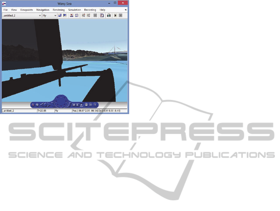
Figure 9: Example of graphical view.
crewmen with realistic physical feedbacks. The
reproduction of the effective behaviour of the real
catamaran suggests to complete the project with a
physical simulator able to interact with the real users
and help the crew to adapt its knowledge to the new
boat.
Future modelling work will concern the
introduction weather conditions (waves and wind) in
order to make the simulator able to reproduce all the
phenomena. The improvement of the graphical
interface appears fundamental to give at the crew the
right feeling. In fact, the graphical interface is the
first element of judgment from the users. It can be
implement using waves, splash on the screen and
more realistic boat details. Finally, a physical model
- consisting in a movable platform controlled by the
simulator - must be introduced to give a realistic
feedback to the crew. The degrees of freedom can
be inserted on the physical interface. It will need of a
movable platform where the movements and the
rotations can be implemented. The rudders and the
sail sheets could be placed in order to give more
reality possible. They has to be able to give to the
user the same forces feeling from the crew when the
boat is on the water and this can be done using some
simple actuators. The improvement of the physical
interface can follow what is already done with the
Formula 1 simulator and pushes the boat simulator
toward a new era.
REFERENCES
Abbott I. H., von Doenhoff A. E., 1959. Theory of wing
sections: Including a Summary of Airfoil Data, Dover
Publications.
Breschan L. M., Lidtker A., Giovannetti L. M., Sampson
A., Vitti M., 2012/2013. America’s Cup Catamaran
Tacking Simulator, University of Southampton.
Comstock, John, 1967. Principles of Naval Architecture,
New York: Society of Naval Architects and Marine
Engineers.
Haack N., 2010/11. C-class catamaran wing performance
optimisation, School of Mechanical, Aerospace and
Civil Engineering, University of Manchester, Tech.
Rep.
Keuning J. A., Sonnenberg U. B., 1998. Approximation of
the Hydrodynamic Forces on a Sailing Yacht based on
the Delft Systematic Yacht Hull Series, International
HISWA Symposium on Yacht Design and
Construction, Amsterdam RAI.
Masuyama Y., Fukasawa T., 2011. Tacking simulation of
sailing yacht with new model of aerodynamic force
variation during tacking manoeuvre, Journal of
Sailing Technology, Article January.
ORC VPP Documentation 2012, Offshore Racing
Congress.
Scarponi M., Shenoi R., Turnock S., Conti P., 2006.
Interaction between yacht-crew system and racing
scenarios combining behavioural mode with VPPs,
19
th
International HISWA Symposium on Yacht
Design Construction, Amsterdam.
icSPORTS2014-InternationalCongressonSportSciencesResearchandTechnologySupport
182
