
Nonlinear Dynamics Based Sensors
A New Class of Devices for System Monitoring
Carlo Famoso, Mattia Frasca and Luigi Fortuna
DIEEI, University of Catania, Viale A. Doria,6, Catania, Italy
Keywords: Sensors, Post-Silicon Materials, Polymers, Nonlinear Systems, Complex Systems, Self-Organization.
Abstract: Post-silicon materials like polymers and solution-based devices allow to design new types of sensors. On
the other hand, the nonlinear dynamic behavior of a class of nonlinear circuits offers the possibility of
conceiving devices where the nonlinearity of the circuit is exploited to realize new mechanisms or improve
classical ones. In this PhD work we discuss the possibility of coupling a new class of materials with
nonlinear dynamic circuits to design a new class of sensors. The results that are included are preliminary
and cover a wide range of applications. In particular advanced sensors based equipment has been studied on
an electromechanical system, in order to monitorize its vibrating behaviour to establish self organizing
phenomenon to control the system.
1 STAGE OF THE RESEARCH
The research regards with the study and the
characterization of a new class of sensors based on
coupling the performances of new materials, like
polymers, and the behaviour of nonlinear electronic
circuits.
The proposal of using this sensors for monitoring
complex self-organizing electromechanical systems
is a second step of the research. At this time, the
sensors have been realized and characterized.
The self-organizing electromechanical system
has been realized by using different architectures.
Preliminary qualitative measurements have been
performed.
2 OUTLINE OF OBJECTIVES
In this project the coupling between new materials
and nonlinear circuits will be explored to design a
new class of sensors.
The principle is to link the variation of a quantity
detected by the material to the change of a parameter
of a chaotic circuit, so that to exploit the parameter
sensitivity of chaotic circuits.
A proof of concept will be given in this study, by
using a type of innovative material/device, such as
Clevios P HC V4, IPMC and water solution cells.
The principle will be demonstrated with a series
of experiments that pave the way to a more intensive
characterization of the devices proposed. The
variation of a quantity, such as humidity, hydratation
level or bending, will be here shown to lead to
significant changes in the dynamical behaviours of
the circuit (in particular, a Chua’s circuit will be
used), that is, the dynamical behaviour of the
nonlinear system bifurcates as a result of the sensing
(Fortuna, Frasca & Xibilia, 2009).
Although the principle may be applied to a
variety of materials, it is particularly interesting
when applied to newly conceived materials which as
such may at a preliminary stage of development , or
characterization, yet they can be successfully used
with such approach.
Moreover, the proposed devices will be adopted
for monitoring a complex electromechanical system,
in order to make advanced studies in self-organizing
complex systems.
3 RESEARCH PROBLEM
In this paper some qualitative preliminary results on
a new class of a sensors (De Silva, 2007) whose core
principle is based on the nonlinear dynamics of a
class of electronic circuits are presented.
13
Famoso C., Frasca M. and Fortuna L..
Nonlinear Dynamics Based Sensors - A New Class of Devices for System Monitoring.
Copyright
c
2014 SCITEPRESS (Science and Technology Publications, Lda.)

In particular, polymeric materials have been
considered. Our study is focused on the use of
clevios-based sensors, Ionic Polymer Metal
Composites (IPMCs), and solution-based systems to
detect various physical quantities like displacement,
humidity, concentration and so on.
The idea is to use the material as the electrical
transducer and insert the electrical transducer into a
nonlinear circuit. The effect of the coupling of these
components with a nonlinear circuit like the Chua’s
circuit is that a variation of the dynamical attractor
will be obtained as result of the change of the
quantity to which the material is sensible.
Chaos has been already demonstrated to be
helpful in improving the performance of sensors and
other equipments, such as sonar sensors, mechanical
systems and other devices (Fortuna, Frasca, &
Rizzo, 2006): in this project, detection of the given
quantity is made possible by the extreme sensitivity
of the circuit to the variations of its parameters
(Fortuna, Frasca, 2006).
In this study sensors based on water solutions,
that have a behaviour that can be comparable with
RC devices with frequency dependent component
values and so are difficult to realize with classical
components, are also reported.
The proposed sensors will be included in a
complex electro mechanical system in order to study
its self organizing behaviour.
4 STATE OF THE ART
In this Section three types of sensors are discussed.
The first one regards the clevios based sensors.
Clevios is a conductive polymer. The clevios used
(Clevios-P HC V4) is commercially available in a
water colloidal suspension.
A layer of thickness of 100μm is coated on a
surface and then treated in an oven at 80
◦
C for 50
minutes. Two different supports have been used: a
glass support and a PVC foil. The first may be used
to realize humidity, wet and PH sensors as the
resistivity of clevios based materials is sensitive to
these quantities.
Figure 1: The clevios based sensor (glass support).
The second type of device (those were the clevios is
coated on flexible PVC foil) may be used to detect
displacements. In this case, the clevios-based sensor
is considered as an electrical bipole whose resistivity
depends on the surface deformation.
Figure 2: The clevios based sensor (PVC support).
The second type of sensor is realized by using
Ionic Polymer Metal Composites (IPMCs). These
materials belong to the class of wet electro-active
polymers.
They are made of an ionic polymer membrane
covered on both sides with Platinum, which realizes
the two electrodes of the device. IPMCs operate with
low voltage signals, are very light, and have both
actuator and sensor characteristics.
Figure 3: IPMC sensor.
They are used after being cut in strips. If an
electric field is applied across the thickness of a
strip, it undergoes a broad bending deformation.
Viceversa, by bending a strip of IPMC, a voltage
arises between the two metallic electrodes.
Hence, IPMCs can operate as motion actuators
or sensors. Instead, in this work, we exploit the
dependence of the resistivity of IPMC on the
hydration of the membrane to realize a humidity
sensor.
Another proposed device is based on the
resistivity change of a water solution. The device
consists of four copper filaments on a plexiglass
substrate which are electrically connected in two
pairs (the two top ones and the two bottom ones).
ICINCO2014-DoctoralConsortium
14
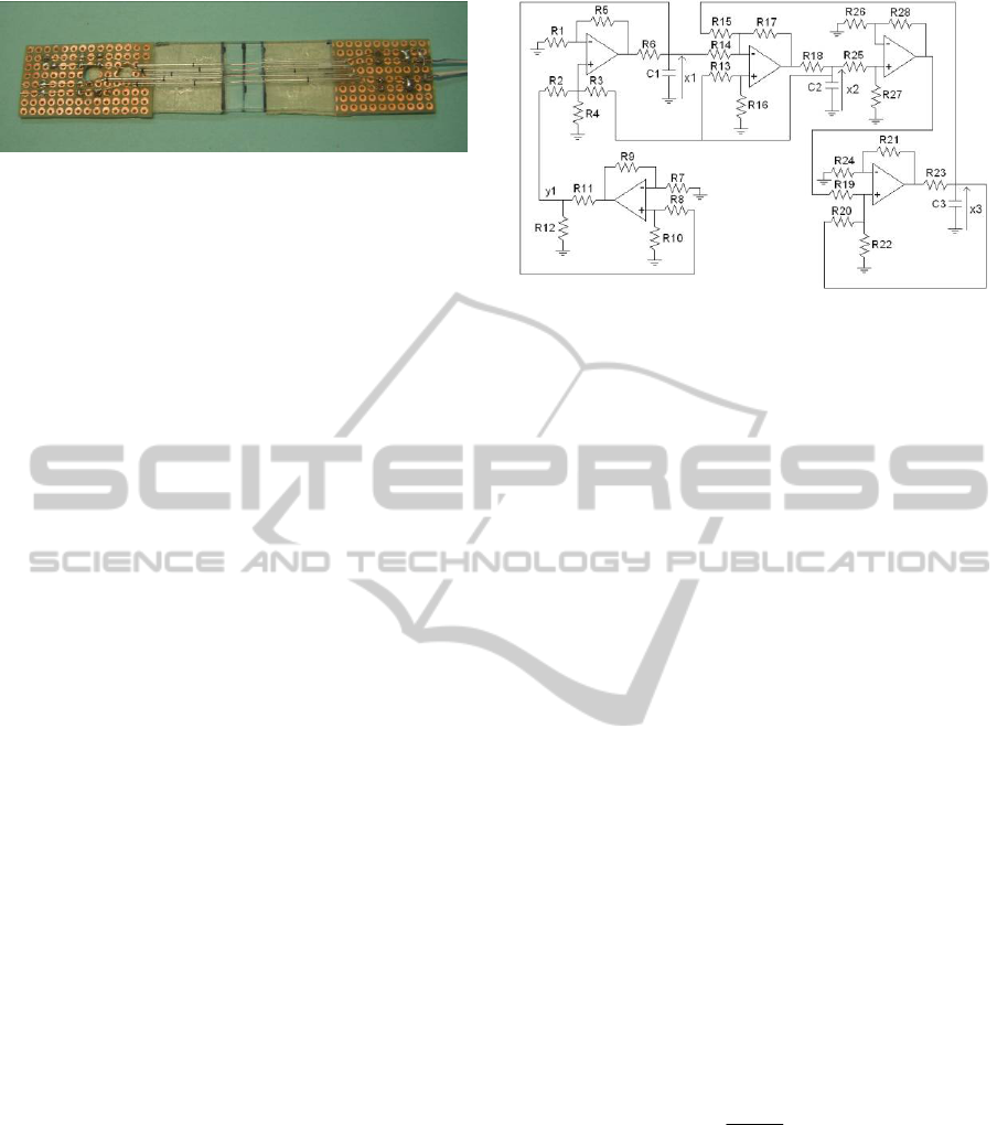
Figure 4: Water solution based sensor.
The space between the filaments hosts a small
quantity of a water solution so that the value of the
resistance measured at the two terminals of the
device is made dependent on the quantity of water.
Figure 1 shows the first clevios-based device. It
is realized on a rigid glass support, the sensor area
has a length equal to 70mm and width equal to
22mm.
Figure 2 shows the second clevios-based device.
This is realized on a PVC (3M Temflex 1500) of
thickness equal to 0.3mm. The active area of the
sensor measures 55mm x 15mm.
Figure 3 shows the IPMC strip used. The size is
44mm x 9mm. The IPMC material has been realized
with the procedure detailed in Arena et al.(2006).
Figure 4 shows the last device. It is realized by
fixing four copper wires on a plexiglass support (of
thickness 2mm). Each wire has diameter equal to
0.22mm. The distance between each pair of wires is
1.5mm. The wires are isolated by glass microtubules
with the only exception of a window of 10mm of
length which constitutes the active area of the
sensor.
5 METHODOLOGY
In this Section we briefly describe some experiments
to show the proof of concept of the coupling of new
materials and nonlinear circuits.
As discussed in Section 4, all the devices
illustrated can be viewed as two terminals devices.
The principle with which they have been coupled to
the nonlinear circuit is common for all the devices.
Starting from the Chua’s circuit (Madan, 1993),
we identify one resistor of the circuit as the
bifurcation parameter. In particular, without any loss
of generality, we have taken into account the so-
called CNN-based implementation of the Chua’s
circuit (Fortuna, Frasca & Xibilia, 2009), whose
electrical scheme is shown in Fig. 5, and identified
as bifurcation parameter the resistor R
6
.
Figure 5: Electrical scheme of the CNN-based
implementation of the Chua’s circuit. The following
components have been used: R
1
=4kΩ, R
2
=13.3kΩ,
R
3
=5.6kΩ, R
4
=20kΩ, R
5
=20kΩ, R
6
fixed from experiment
to experiment as the sensor device, R
7
=112kΩ, R
8
=112kΩ,
R
9
=1MΩ, R
10
=1MΩ, R
11
=12.1kΩ, R
12
=1kΩ, R
13
=51.1kΩ,
R
14
=100kΩ, R
15
=100kΩ, R
16
=100kΩ, R
17
=100kΩ,
R
18
=1kΩ, R
19
=8.2kΩ, R
20
=100kΩ, R
21
=100kΩ,
R
22
=7.8kΩ, R
23
=1kΩ, C
1
=C
2
=C
3
=100nF.
The power supply has been fixed to ±9V.
The circuit obeys to the dimensionless equations:
)]([ xhyx
(1)
zyxy
yz
where β = 14.286 and h(x) represents the
nonlinearity of the system:
h(x) = m
1
x + 0.5(m
0
- m
1
)(|x+1| - |x-1|) (2)
with: m
0
= - 1/7 and m
1
= 2/7
and
x = x
1
, y = x
2
, z = x
3
(3)
being the state variables.
For the sake of brevity, we refer to Fortuna et al.
(2009) for a more detailed discussion on the Chua’s
circuit and the CNN-based implementation reported
in Fig. 5.
Here, we briefly mention that α is a key
bifurcation parameter and it is related to the
component values by:
68
125
RR
RR
(4)
We have thus kept constant R
3
, R
5
and R
18
and in
place of the R
6
we have connected each of the
sensors described in Section 4.
In some cases, where the typical values of
resistance given by the device are out of the range of
the operating conditions of the Chua’s circuit, a
resistor indicated in the following as R
p
, has been
NonlinearDynamicsBasedSensors-ANewClassofDevicesforSystemMonitoring
15
also connected in parallel to the device with respect
to them.
The first experiment refers to the use of the
clevios based sensor of Fig. 1. This is a sensor
realized by coating the clevios on a rigid support.
The two terminals of this device have been
connected to the Chua’s circuit and the
experimentally obtained attractors for two different
operating conditions of the sensor have been
reported in Fig. 6.
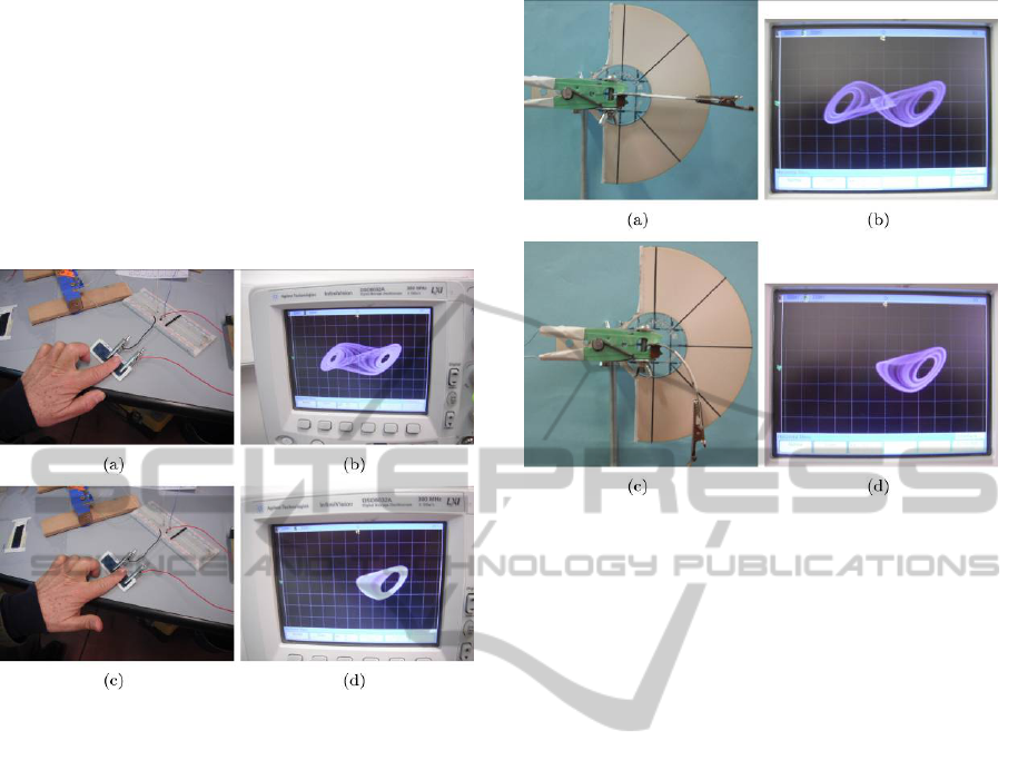
Figure 6: Wet detection experiment. (a) A dry finger is
applied to the sensor. (b) Attractor corresponding to the
experimental condition of dry finger. (c) A wet finger is
applied to the sensor. (d) Attractor corresponding to the
experimental condition of wet finger.
Figure 6(a) shows the sensor where a dry finger
has been applied in the active area. The
corresponding attractor is shown in Fig. 6(b). It is
the well-known Chua’s double scroll attractor.
When a wet finger is applied to the sensor, as in
Fig. 6(c), the attractor in Fig. 6(d), that is, the so-
called single scroll attractor, is obtained. The
different dynamical behaviours obtained allow to
easily distinguish the different operating conditions
of the sensor.
The value of the resistance of the clevios based
sensor in dry conditions is 97kΩ, this is outside the
typical range of values used for R
6
in the Chua’s
circuit. Therefore, in this experiment, a parallel
resistor of value equal to R
p
= 375Ω has been used.
In the second experiment the sensor based on
clevios deposition on a flexible support is
considered. The experiment is illustrated in Fig. 7.
When the sensor is in the horizontal position
(Fig. 7(a)), the attractor obtained is the Chua’s
double scroll attractor (Fig. 7(b)).
Figure 7: Deformation detection experiment. (a) Clevios-
based sensor in the horizontal position. (b) Attractor
corresponding to the experimental condition of horizontal
position. (c) Deformed position for the clevios-based
sensor. (d) Attractor corresponding to the experimental
condition of wet finger.
In correspondence of a bending with an angle of
45° (Fig. 7(c)), the Chua’s single scroll attractor is
obtained (Fig. 7(d)).
In this experiment R
p
has been fixed as
R
p
=447Ω. The resistance of the clevios device
changes from 4965Ω in the horizontal position to
5530Ω when bended.
The experiment based on the use of an IPMC
strip is illustrated in Fig. 8, through different frames
of a video recording the attractor obtained on the
oscilloscope.
At time t = 0 (Fig. 7(a)) a limit cycle periodic
attractor is evident. When the IPMC membrane is
hydrated by inserting it in a small container filled of
water (this takes a few seconds after the beginning
of the experiment), the attractor changes. Due to the
presence of equivalent resistive and capacitive
effects in the membrane, a switching dynamics
emerges. The dynamics is characterized by
oscillations which spiral towards one of the two
unstable equilibrium points of the circuit.
Before reaching the equilibrium, the trajectory
suddenly jumps to the other lobe and starts again
spiralling, this time towards the other equilibrium.
This repeats until the membrane becomes again wet.
In Fig. 7(b)-(f) we show the trajectory observed in
the oscilloscope up to 3 minutes after the
hydratation. The phenomenon maintains for about
ICINCO2014-DoctoralConsortium
16
15 minutes. In this experiment R
p
has been fixed to
R
p
= 413Ω.
In the fourth experiment the sensor shown in
Fig. 4 is used. It has been directly substituted to the
R
6
resistor without inserting further parallel resistor.
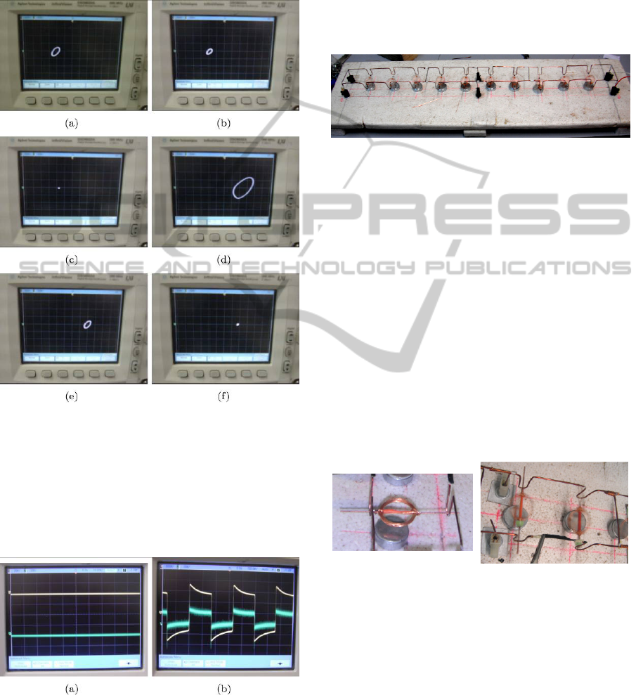
Figure 8: IPMC hydratation sensor experiment. (a) t = 0s;
(b) t = 60s; (c) t = 105s; (d) t = 120s; (e) t = 150s; (f) t =
180s.
When the sensing area is dry, the attractor is a
stable equilibrium point (Fig. 9(a)). On the contrary,
when a small quantity of water (or even a wet
finger) is placed in the active area of the sensor, the
circuit begins to oscillate as shown in Fig. 9(b).
Figure 9: Experiment based on the sensor of Fig. 4:
(a) attractor obtained for an experimental dry condition;
(b) waveforms corresponding to wet experimental
conditions.
6 EXPECTED OUTCOME
The core of PhD Thesis is the possibility of having a
global real time behaviour monitoring of a complex
electromechanical equipment.
The system has been conceived in order to study
experimentally the effect of self-organizing
phenomena in coupled electromechanical devices.
Figure 10: The electromechanical structure built on a
flexible metallic support with the coils. The white base is
made of polystyrene foam in order to absorb all external
vibrations. Immediately below the flexible structure
magnets are placed.
The project consists in the study of self
organizing structures that allows the synchronization
of a set of single coils. The possibility of
synchronizing mechanical systems by using
mechanical coupling has been proposed by Ditto et
al. (1995). In that, a study has been proved
numerically how mechanical random dissymmetry
does favourite the synchronization of simple
pendula.
In the proposed study, instead of pendula, coils
that are directly coupled by a flexible support, have
been considered. The irregularity of the coils
movements generate a random forcing signals for
the mechanical structures.
Figure 11: The detail of the coil with its insertion point on
the flexible support.
What we want to prove consists in studying
experimentally the phenomenon and to propose
several suitable architectures where the irregular
movements of the coils should produce a self
organizing phenomenon in order both to have a
regularization in the angular speed coils and in the
control of the global mechanical structure.
NonlinearDynamicsBasedSensors-ANewClassofDevicesforSystemMonitoring
17
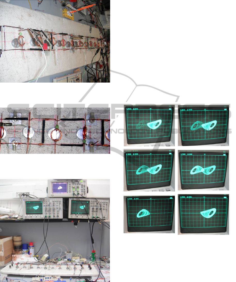
Figure 12: The complete electromechanical structure, with
coils, magnets and the clevios based vibration sensors
positioned on some sections of the structure.
Figure 13: The particular of the elettromechanical support
with, in black, the clevios based vibration sensors
positioned on some branches of the structure.
Figure 14: An overview of the complete system connected
to three Chua's circuits.
In order to achieve the previous task, a
qualitative vibrating measurement system is studied
in order to have a global behaviour of the system’s
vibrations. This should be made considering
distributed sensors in the various beams of the
structure. The adopted sensors surface have been
made by clevios based sensors.
Each sensor that responds dynamically as a
variation of ohmic resistance to the vibration is
coupled to a chaotic device. That does change
attractor when the vibration does occur.
An overview of the complete system connected
to three Chua's circuits, and the corresponding
dynamic responses, is shown in fig. 15.
The intermittency of the vibrating coils and his
frequency spectrum are detected by the strange
attractor shape changing and can be quantified by
the intermittency condition of each attractor.
Figure 15: The intermittency of a strange attractor in
response to the vibrations of the structure transduced by
one of clevios based sensors.
In Fig. 15 the variations of the shape of the so-
called single scroll attractor, are shown. The
different dynamical behaviours obtained allows to
easily distinguish the different operating conditions
of one of the clevios based sensors placed on the
flexible structure.
The complexity of the dynamics of the
electromechanical system is more appreciated if
other sensors are connected to as many Chua’s
circuits.
ICINCO2014-DoctoralConsortium
18
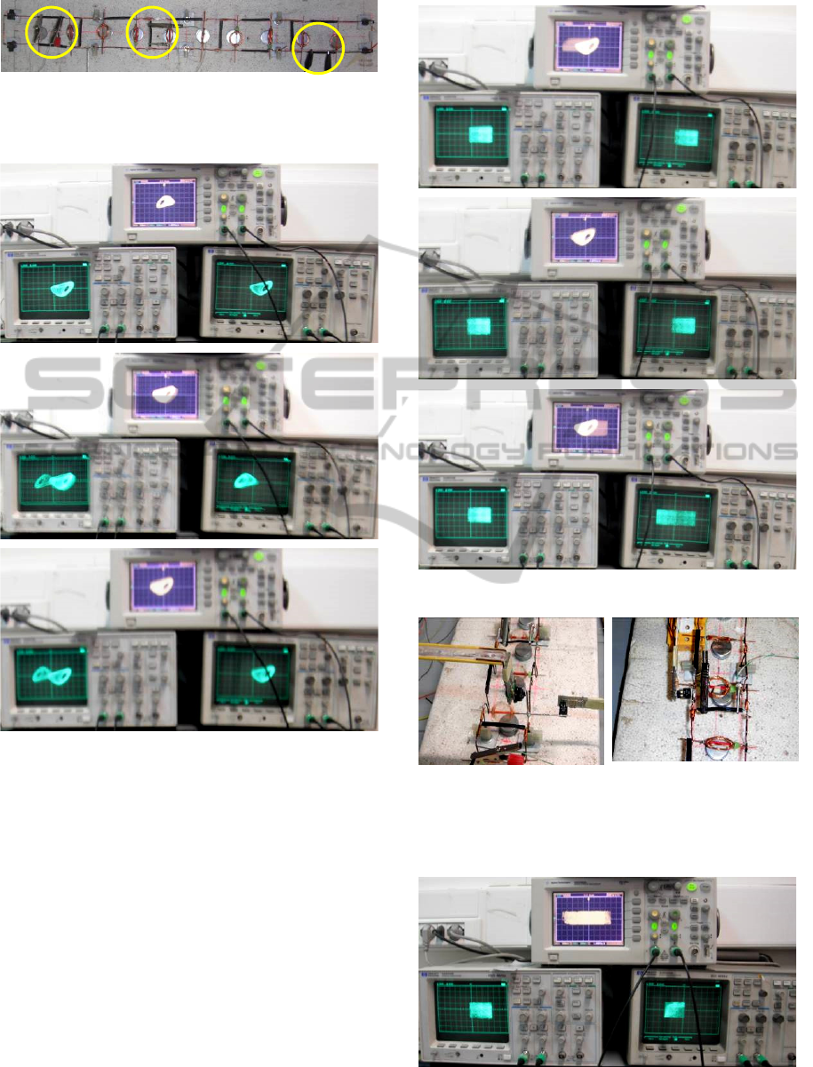
Figure 16: The position of the clevios based sensors on the
electromechanical structure connected to Chua’s circuits
are shown.
Figure 17: The intermittency of a strange attractor in
response to the vibrations of the structure transduced by
three clevios based sensors.
The observation of the dynamics of these non-
linear circuits (which is conducted qualitatively by
means of the variation of the shape of their strange
attractors), highlights not only the interaction of the
sensor with the structure, but also how the structure
allows its elements interact between them.
Moreover, to have more sensors, in order to
establish such a type of vibration, optical sensor
have been considered in the mechanical structure.
Figure 18: Intermittency behaviour and strange attractors.
(a) (b)
Figure 19: The optical sensors considered in the
mechanical structure. In (b) the optical sensor estimate the
oscillations on the vertical plane, in (a) the optical sensors
estimate the oscillations on two normal planes.
Figure 20: Intermittency behaviour and strange attractors
for mutual interference vibrations.
NonlinearDynamicsBasedSensors-ANewClassofDevicesforSystemMonitoring
19
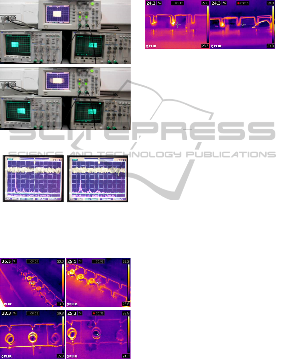
Figure 21: Intermittency behaviour and strange attractors
for mutual interference vibrations. (cont.)
(a) (b)
Figure 22: The waveforms generated by the optical sensor
for the oscillations in the vertical plane and its FFT at two
different speed of rotation of the coils. The speed of
rotation in (a) is greater than in (b).
In order to achieve also a global monitoring of the
system, thermal measurement will be acquired.
Figure 23: Thermal camera pictures of the structure.
Higher temperatures can
b
e observed in slower coils since
higher currents flow into them.
Figure 24: Thermal camera pictures of the structure.
Higher temperatures can be observed in slower coils since
higher currents flow into them. (cont.)
In this way a qualitative behaviour also from an
electrical point of view can be achieved.
Even if each coil can be modelled by the
following linear equations:
)(tiKbJ
i
a
i
t
iiii
(5)
)()( tvKRti
d
t
di
L
i
a
ii
e
i
a
i
a
i
a
i
a
where:
i : indicate the generic coil
i
J : Moment of inertia of the coil
i
: Angular position of the coil
i
b : Viscous friction coefficient
i
t
K : Coil torque constant
)(ti
i
a
: Current coil
i
a
R
: Coil’s resistance
i
a
L : Coil’s inductance
i
e
K : Coil electro magnetic force constant
)(tv
i
a
: Voltage coil
nonlinear phenomenon can arise both locally and
globally. This effect will be studied in order to
achieve the self-organizing conditions.
In this way a global mathematical model can be
proposed and a setup measurement equipment will
be available.
The study will be performed for a large number
of coils (about 100) and will be the cornerstone
mechanical forced system that should be used for
qualitative models of complex phenomena like
earthquakes and mechanical vibrations in distributed
forced mechanical equipments.
REFERENCES
Arena, P., Bonomo, C., Fortuna, L., Frasca, M., & S.
Graziani, 2006. Design and Control of an IPMC
Wormlike Robot. IEEE Trans. Systems, Man and
ICINCO2014-DoctoralConsortium
20

Cybernetics-Part B: Cybernetics, vol. 36, no. 5, pp.
1044-1052.
Braiman, Y., Lindner, J.F., Ditto, W.L., 1995. Taming
Spatiotemporal Chaos with Disorder. Nature vol 378,
pp. 465-467.
De Silva, C., W., 2007. Sensor and Actuators: Control
System Instrumentation. CRC Press.
Fortuna, L., Frasca, M., 2006. Use of Chaos to Improve
Equipments, in S. Baglio & A. Bulsara (eds), Device
Applications of Nonlinear Dynamics, Springer
Complexity, Springer.
Fortuna, L., Frasca, M., Rizzo, A., 2003. Chaotic Pulse
Position Modulation to Improve the Efficiency of
Sonar Sensors, Instrumentation and Measurement,
IEEE Transactions on, vol. 52, no. 6 , pp 1809 -1814.
Fortuna, L, Frasca, M., & Xibilia, M. G., 2009. Chua's
Circuit Implementations: Yesterday, Today and
Tomorrow, Series on Nonlinear Science, Series A -
Vol. 65, World Scientific. Singapore.
Madan, R., 1993. Chua's circuit: A Paradigm for Chaos,
World Scientific. Singapore.
NonlinearDynamicsBasedSensors-ANewClassofDevicesforSystemMonitoring
21
