Intelligent Path Panning Towards Collision-free Cooperating
Industrial Robots
L. Larsen
1
, J. Kim
2
and M. Kupke
1
1
German Aerospace Center (DLR), Center for Lightweight Production Technology (ZLP),
Am Technologiezentrum 4, Augsburg, Germany
2
University of Augsburg, Human Centered Multimedia, Universitaetsstr. 6a, Augsburg, Germany
1 INTRODUCTION
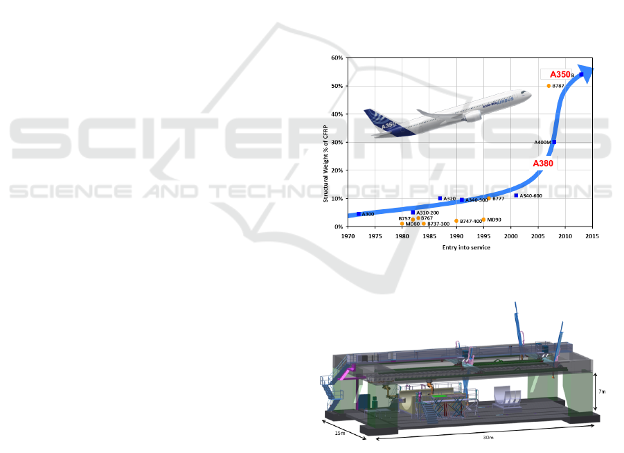
Due to raising costs of energy and the increasing
request for environment-friendly products, there is
a huge demand for lighter vehicles, helicopters or
airplanes made of carbon fibre reinforced plastics
(CFRP). In the last years the structural weight in per-
centage of CFRPs in airplane production was clearly
rising. The AIRBUS A380 with about 20 % and
the AIRBUS A350 with about 50 % (see Figure1).
Carbon fibres are very thin and have a high tensile
strength. Products which are assembled from CFRP
offer one of the highest strength-to-weight ratio com-
pared to any other material and also offer superior
thermal and conductive properties. These properties
makes the material very famous in car, aerospace, ma-
rine and sports industry.
To use CFRPs in a mass production it is impor-
tant to produce lightweight products cost-efficiently
in high quality and quantity. To achieve these goals,
a high degree of automation is necessary. For this
reason, the German Aerospace Center (DLR) devel-
oped a robotic portal system within the Center for
Lightweight-Production-Technology (ZLP). In this
system, large parts of CFRP for e.g. the aerospace
industry and the wind energy industry can be manu-
factured automatically. It supports three portal robots
and two industrial robots on a linear track, enabling
them to move along the middle beam. Its dimensions
are about 30 m in x-, 15 m in y- and 7 m in z-direction,
see Figure 2. All robots and portals in the robotic cell
share the same workspace so they can work together
which makes the programming one the one side very
difficult and one the other side very interesting. To
achieve the goal of low-cost production, the DLR con-
centrates on dry fibre placement of large carbon fab-
rics. This ensures higher lay up rates than tape laying
which reduces manufacturing costs of large compos-
ite structures. To handle these large and sensitive car-
bon fibre fabrics, it is necessary to work with coop-
erating robots, which requires a sophisticated control
Figure 1: Rising overall structural CFRP weight in airplane
production (source: AIRBUS).
Figure 2: Multi-variant-production cell (MFZ) containing
two industrial robots on a linear track and three portal robots
in the same working space. The dimensions of the cell are
30 m in x-, 15 m in y- and 7 m in z-direction.
strategy.
2 RESEARCH PROBLEM
In conventional industrial robotic cells e.g. in an au-
tomotive assembly line the robots execute the same
task for a period of many month or years. The move-
ments of the robots are hard-coded for one process
with respect to no occurring collision. Normally a
high amount of time is needed to program the robots.
39
Larsen L., Kim J. and Kupke M..
Intelligent Path Panning Towards Collision-free Cooperating Industrial Robots.
Copyright
c
2014 SCITEPRESS (Science and Technology Publications, Lda.)
A reconfiguration of the cells implies a high resource
effort.
In the automotive industry the cycle time is mea-
sured in seconds and in the aerospace industry it is
measured in hours. One reason for that is that the as-
semblies e.g. a fuselage or a wing are much bigger.
Another reason is that the requirements on the accu-
racy are very high. Bringing to mind that transporting
a dry fibre cut piece is like transporting a table dish it
becomes clear that the process speed is not the only
challenge rather it is the quality of the process and the
resulting product.
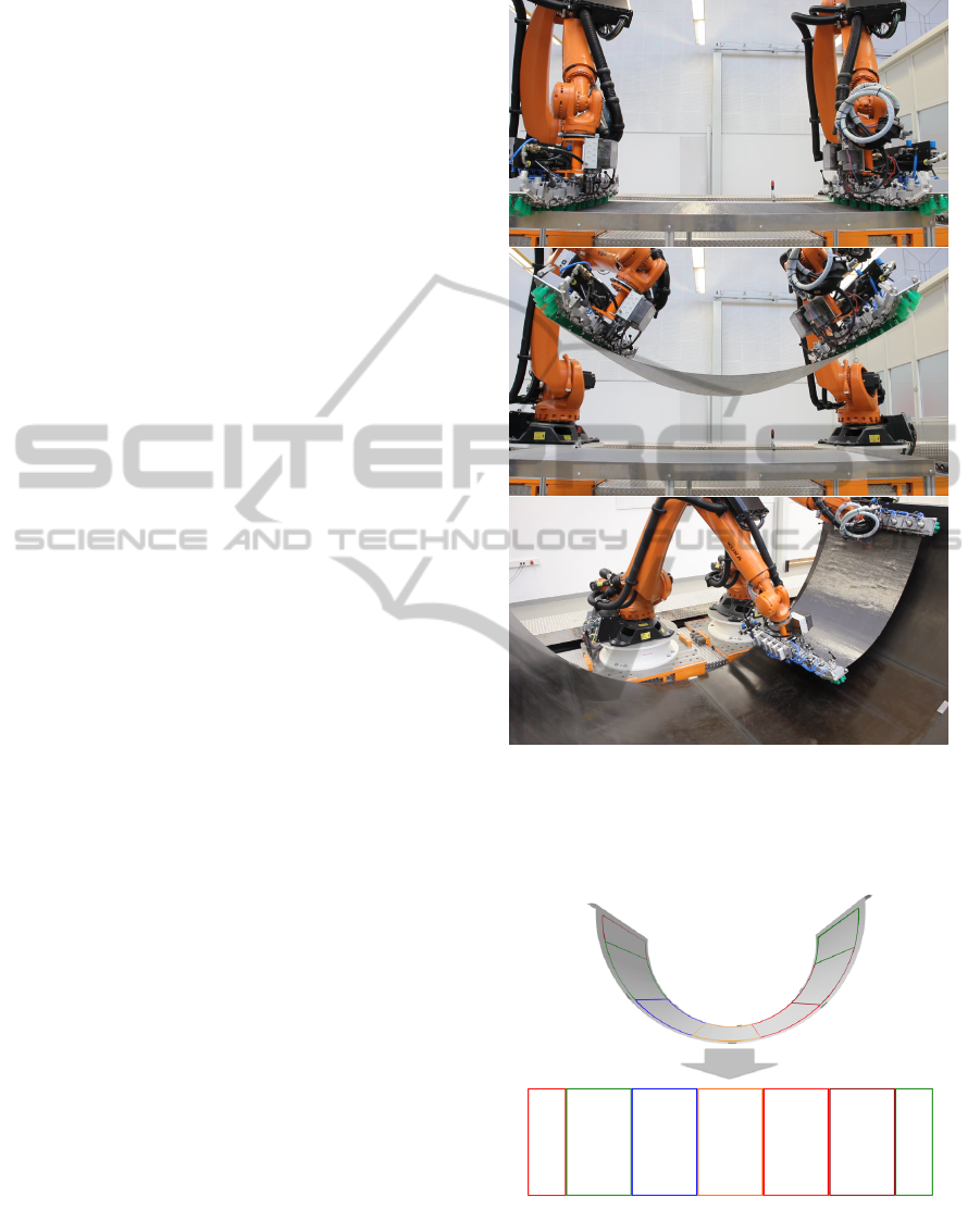
Like it is easier to set a table with two persons it
is also easier to transport a large four meter dry fibre
cut piece with two robots. Figure 3 shows an exam-
ple process for the layup of carbon fibre cut pieces
with cooperating robots. First the cut piece is grabbed
from a plane table. For lifting the cut pieces the robots
have special designed end-effector which can handle
the material very gentle. The material is very perme-
able to air. Therefore the end-effectors don’t work
with vacuum to grab the textile but with a high flow
rate like a vacuum cleaner. After grabbing the ma-
terial it is transported on a linear axis to a negative
tooling of the assembly. In this case it is the lower
half of a fuselage with the dimension of an AIRBUS
A320. In the mould the textile is placed and fixated.
The position were the cut pieces must be placed
in the 3D mould is defined by the designer in an com-
puter aided design (CAD) tool like CATIA Compos-
ites Design (CPD). With that tool different carbon fi-
bre cut pieces with different fibre orientations are put
on each other. Depending on the demands of the as-
sembly this can be five up to more than 20 layers with
thousands of cut pieces for a whole fuselage. As a re-
sult of the design phase the designer exports the exact
lay down position of every cut piece. This lay up defi-
nition is called plybook. Figure 4 shows the first layer
from a plybook for the example process in 3D and un-
wind to 2D. The coloured lines show the outlines of
the cut pieces. The gripping position also comes from
the CAD software.
3 STATE OF THE ART
This chapter shows the state of the art of collision de-
tection and path planning both in science and in in-
dustry.
Figure 3: A typical dry fibre placement process for the pro-
duction of the lower half of an airplane fuselage with the
size of an AIRBUS A320 a.) grabbing a 4-6 m cut piece
from a flat plane b.) transport from grabbing position to lay
up position c.) lay up of cut piece in 3 dimensional mould.
Figure 4: First layer of the plybook of the lower half of a
fuselage in 3D and unwind to 2D.
ICINCO2014-DoctoralConsortium
40

3.1 State of the Art in Science
3.1.1 Collision Detection
Industrial manipulators have high masses which are
moved. That makes it very important to detect colli-
sions of the robot with other robots or the environment
reliable.
Most collision detection algorithms distinguish
between a broad- and a near-phase (Kockara et al.,
2007). In the broad-phase objects are detected which
are inspected more accurately in the near-phase.
The most common methods to check the broad-
phase are exhaustive search, sweep and prune (Baraff,
2001) (Lin and Manocha, 1993) and hierarchical hash
tables (Mirtich, 1996). In industrial robot applications
the position of the robot is known at every time with
an accuracy of about ±3 mm. This makes the detec-
tion of the broad-phase very easy.
The algorithms to calculate the near-phase are
mostly divided into four groups: feature-based,
simplex-based, image-space and Spatial Data Struc-
tures (Mirtich, 1996). Feature-based algorithms di-
rectly work on the primitive form of the object.
Famous representatives are polygonal intersection
(Moore and Wilhelms, 1988), Lin-Canny (Lin and
Canny, 1991), V-Clip (Mirtich, 1998) and SWIFT
(Ehmann and Lin, 2000).
Simplex-based algorithms are based on a geo-
metrical approach which describes a n-dimensional
polygon which is the convex hull of n+1 vertices.
With increasing dimensionality this results in the fol-
lowing objects: point, line, triangle, triangular pyra-
mid. The Gilbert-Johnson-Keerthi (GJK) distance al-
gorithm is the most famous representative (Gilbert,
1988) (Cameron, 1997) (van den Bergen, 1999)
(van den Bergen, 2001) (Gilbert and Foo, 1990).
The family of Image-Space algorithms (ISB) de-
tects collisions by the calculation of overlappings.
For the detection of collisions in dynamic environ-
ments the ISBs are very efficient, because the cal-
culation can be parallelized very easy and put on an
graphical processing unit (GPU). Famous examples
are (Jang, 2006) (Stewart, 2008) (Heidelberger, 2004)
(Jang et al., 2007) (Myszkowski et al., 1995) (Heidel-
berger et al., 2003).
Bounding Volume Hierarchies (BVH) belong to
the family of Spatial Data Structures. In (Figueiredo
et al., 2006) an overview over the different types can
be found. One kind are Bounding Spheres (Bradshaw
and O’Sullivan, 2004). The use of Bounding Spheres
is very famous for collision detection because the cal-
culation cost are very simple and fast. Another group
are the Bounding Boxes (BB) which describe objects
better than spheres. They are often used in applica-
tions like ray-tracing. Special forms of the bounding
boxes are Axis-Aligned Bounding Boxes (AABB),
which are aligned on the coordinate axes. They are
normally defined by two points which define the ver-
tices on the cross diagonal. Another form are arbitrar-
ily oriented boxes called Oriented Bounding Boxes
(OBB). Furthermore objects can be defined by poly-
hedrons. These bounding boxes are called k-Discrete
Oriented Polytopes (k-DOP). In contrast to OBB, k-
DOPs allow more bounding surfaces wherefore they
can describe objects better.
Due to the fact that modern measuring systems,
like a laser-scanner or a depth camera often create
point clouds as representation of the environment an-
other possibility of collision detection is the direct
calculation on these clouds (Klein and Zachmann,
2004) (Pan et al., 2011) (Yakut, 2010).
In the industrial environment there are just a few
approaches which deal with collision avoidance based
on environment data without external sensors. In
(Fawaz et al., 2009) a virtual simulator is introduced
which allows an on-line collision monitoring. (Pe-
drocchi et al., 2009) picks an algorithm based on po-
tential field method as central theme which can de-
tect and avoid collisions between industrial robots.
In (Cheng, 1995) a four dimensional (three spa-
tial dimensions and time) real-time collision detec-
tion technique for the UPS arm, a ten degree-of-
freedom hybrid serial-and-parallel redundant robotic
arm is shown. For the collision detection the geo-
metrical information is separated from the time by s-
formulations. After the separation the occurring col-
lisions can be calculated by bisection method in re-
altime. In (Hermann, 2013) a real-time collision de-
tection system, which is optimized for the calculation
on CUDA Graphical Processing Unit (GPU), is pre-
sented. The system is based on two voxelmaps which
are put on the GPU.
3.1.2 Path Planning of Industrial Robots
The main goal of motion or path-planning is to
find a continuous motion that connects a starting-
and destination-point, while avoiding collisions with
known obstacles. For the calculation the robot and the
obstacles must be defined in a 2D or 3D workspace.
Normally the coordinates that define the position and
the orientation of a coordinate frame that is attached
to a rigid body in three-dimensional space define its
configuration space. In robotics the configuration
space defines all positions of an end-effector which is
attached to a robot in three-dimensional space (Craig,
2005).
Another space which describes a position of a
IntelligentPathPanningTowardsCollision-freeCooperatingIndustrialRobots
41

robot is the joint space. The set of joint positions for
each link of the robot is called joint space. The for-
ward and backward kinematic of a robot manipulator
is the mapping between the configuration space and
the joint space. The forward kinematic maps the joint
positions to the coordinate positions and the backward
from coordinate to joint positions. Finding a path for
a robot also means to find the path in the configuration
space and afterwards map it back to joint space.
For the determination of two- or tree-dimensional
path planning problems exist different grid based
methods, where a grid is put over the working space
of the robot. Famous examples are depth-first search,
breadth-first search, Dijkstra and A*. A very good
explanation of these algorithms can be found here
(LaValle, 2006).
Another group are the geometrical algorithms, in-
cluding Visibility Graphs (Scott and Vuillemin, 1986)
and Cell Decomposition (LaValle, 2006). A Visibil-
ity Graph reflects the free view between different ver-
tices in a scene. By adding a start and an endpoint
the shortest path can be found with the Dijkstra algo-
rithm. The Cell Decomposition algorithm divides the
scene in smaller regions (cells). After that the short-
est and easiest connection between different cells is
calculated with a tree data structure.
Path planning for robotic manipulators in scien-
tific of industrial applications is very interesting and
challenging problem especially if the environment of
the robot is not static e.g. when there is human-
machine interaction or multiple robots are in the same
workspace.
For high dimensional path detection problems
the Potential Field Method is very practical. The
basic concept of that method is that obstacles and the
robot are seen as electrified particles with opposite
sign and the goal has the same sign as the robot.
The algorithm calculates a path where the distance
between the robot and the obstacles is big enough
and the length between the start- and the endpoint is
as small as possible (Barraquand et al., 1992) (Daily
and Bevly, 2008) (Kitamura et al., 1995) (Tang et al.,
2010).
Single Robot Path Planning. There are some exam-
ples for the path planning of a single robot manip-
ulator both off-line and on-line using computational
intelligence methods.
In (Saravanan et al., 2007) an off-line al-
gorithm based on an evolutionary algorithm is
presented which calculates an optimal trajectory
for a PUMA560 6-DOF manipulator. The aim of
the algorithm is to minimize the multi-criterion
cost function with actuator constraints, joint limits
and payload constraints by considering dynamic
constraints by motion. In (Ting et al., 2002) a
collision free off-line path planning algorithm is
introduced which is based on the assigned marked
number of the passable region via wave expansion
method. In (Klanke et al., 2006) an on-line path
planner for a redundant Mitsubishi PA-10 arm with
7-DOF is introduced which can deal with stationary,
non stationary or unknown environment. The method
works with the grid based dynamic wave expansions
neural network (Lebedev et al., 2005). In (Huang
and Lian, 1997) a model-free hybrid fuzzy logic and
neural network algorithm was proposed to control a
4-DOF manipulator. A conventional fuzzy controller
was used for the rough adjustment of each joint.
Another controller which used a back-propagation
(BP) neural network was designed to control the
coupling between the links. By the combination of
fuzzy and neural network the learning time of the
neural network could be dramatically reduced. In
(Zavlangas and Tzafestas, 2000) a fuzzy approach
is presented for the on-line local navigation and
obstacle avoidance for an industrial 3-DOF robotic
manipulator. The system is divided into separate
fuzzy units each of them controlling a robotic joint
separately. In (Cueva and Ramos, 2002) a method
based on genetic algorithm is presented to calculate
collision free paths in 2D for redundant or non redun-
dant manipulators. In (Kazem et al., 2008) a genetic
algorithm is proposed to optimize the point-to-point
trajectory of a redundant 3-link arm. The algorithm
can find a collision free path with minimum travelling
time and space. In (Gosselinj, 1994) an approach
is presented using neural network and fuzzy logic
for the path planning of a 3-link manipulator in 2D.
The neural network is used to predict in real-time the
trajectory of a moving object filmed by a camera to
be caught by the manipulator. The fuzzy logic is used
to control the joints of the robot.
Cooperating Robots Path Planning. Path planning
for cooperating mobile robots is a popular research
area however in the area of cooperating industrial ma-
nipulators are just a few research results.
In (Juan C. Fraile and Dodds, 1999) a trajectory
planning system is introduced which calculates tra-
jectories with a minimum time performance for three
industrial manipulators each with five joints sharing
the same workspace and working on the same work-
piece. (Tzafestas et al., 1998) present a path planning
system, for a cooperating three-robot system transfer-
ring a large object from a start to a final position. The
method is based on the master-and-two-slave mode
where one robot is the master pretending to do the
movements and the other robots are following. (Ali
et al., 2002) present a path planning algorithm using
ICINCO2014-DoctoralConsortium
42

coevolutionary genetic algorithm (CGA) for two co-
operative robots. A coevolutionary genetic search is
performed on the configuration space to find the mini-
mum and collision free path. Finally the CGA method
is compared against A* and genetic algorithms (GA).
In (Curkovic et al., 2013) a coevolutionary algorithm
for the collision free motion planning of two 6-DOF
industrial manipulators with overlapping workspaces
is presented. The planning is based on a hall of fame -
Pareto-based co-evolutionary algorithm which allows
the real-time calculation of the path. (Garg and Ku-
mar, 2002) present a strategy for the determination of
an optimal path for multiple 2-link robots in 2D re-
quiring the least amount of torque with genetic algo-
rithm. (Li et al., 2012) introduce a system using neu-
ral network for the control of multiple redundant ma-
nipulators moving the same payload together. Each
module in the neural network controls one manipula-
tor and all networks together solve the common task.
3.2 State of the Art in Industry
3.2.1 On-line Programming
A common on-line programming technology is the
manual teach-in of a robot. This means the process of
generating a sequence of robot poses or instructions
the robot has to do to accomplish the desired task.
To do that the programmer has to know the program-
ming language and the teach panel of the robot he
uses. Normally the teach panel has buttons for saving
and editing the program and buttons or a 3D mouse to
move the robot. The programmer can move the robot
in different coordinate systems which makes the po-
sitioning more intuitive. The robot offers a Cartesian
world coordinate system and a tool center point (TCP)
Cartesian coordinate system. Furthermore the robot
offers the possibility to define a base coordinate sys-
tem for a work piece. Another possibility is to move
the joints of the robot. Between the point the pro-
grammer can define in which motion profile e.g. lin-
ear or point-to-point and with which acceleration and
velocity the robot should move.
The advantage of the teach-in process is that it
is very clear for the user because he has a concrete
reference to the process while programming. A task
in a working space without many obstacles is easy to
program. If the working space is very complex with
many obstacles and a multiple bent work pieces where
many interpolation points are needed the teach-in is
very difficult. Another disadvantage of this method is
that it is a very time consuming process. After a raw
teach-in follows another very time consuming opti-
mization of the trajectory of the robot by optimizing
single points and adapting the velocity profile for the
movements. To do that the programmer has to run the
created program on-line on the robotic cell. The result
of the teach-in is one solution for the trajectory of the
process which depends on the skills and experience of
the programmer.
For the programming of cooperating robots the
robot manufacturer KUKA offers an application
package called RoboTeam which makes it possible
that up to 15 robots can work in a team. RoboTeam
makes it possible that robots can do load sharing or
workpieces can be processed during a transfer from
different robots. The robots keep their standard con-
troller and are connected and synchronized with a lo-
cal network. The application package offers two func-
tionality types. The motion cooperation and the pro-
gram cooperation.
In this way, all tasks that directly affect the robot
group are also carried out autonomously by the group.
By setting shared synchronization markers, it is pos-
sible to synchronize the program sequences of several
robots e.g. the synchronized grabbing of a workpiece.
The distributed sequence control of complete manu-
facturing programs is carried out decentralised within
the networked robot group. Each robot in the group
can start a manufacturing program on another robot
or wait for the end of a manufacturing program. This
means that it is possible to dispense with an external
PLC in many cases, leading to significant cost reduc-
tions for the production cell. The program operation
allows the synchronization and monitoring of shared
workspaces of the robots.
The motion cooperation allows to geometrically
connect the TCPs of the robots. As a result it is pos-
sible to couple the geometric path of the robots. This
allows a flexible solution for all processes where very
heavy or very large workpieces have to be transported
by more than one robot.
The teach-in of cooperation robots has additional
disadvantages adverse to the teach-in of one robot.
One is that it is very difficult to have an overview off
the teaching process. To avoid collisions while the
teach process there should be minimum one more per-
son. Another disadvantage is that the programming
of two robots is not very user friendly. The program-
mer has to switch between the teach panels of the two
robots all the time.
3.2.2 Off-Line Programming (OLP)
Off-line programming is a simulation based program-
ming of a robot. The robot cell is modelled in the
computer. This can be done by containing obstacles,
tools, jigs and the robots. For the modelling the geom-
etry and the size of all things which are in the cell and
IntelligentPathPanningTowardsCollision-freeCooperatingIndustrialRobots
43

necessary for the process must be exactly known. The
quality of the OLP program significantly rises with
the quality of the model. After the cell is modelled a
collision free path can be manually generated by mov-
ing the robot in the virtual world. Afterwards the path
can be optimized for a fast execution. After the op-
timization the path must be exported to a real robot
program in the appropriate robot language.
The OLP programming has a lot of advantages. It
is possible to test different scenarios of the process be-
fore the cell is build. After that an optimization of the
installation of the process stations can be done before
the cell is built. Another advantage is that the cell can
be taken into operating state directly after completion.
But OLP has also some disadvantages which are
inappropriate for the use in CFRP production. The
biggest drawback is that cooperating robots are not
supported. Another one is that the resulting program
is static and it is not possible to put correction values
to the production process. So the whole quality of the
resulting assembly mainly depends on the accuracy of
the virtual model of the cell in the OLP tool.
4 METHODOLOGY
The goal of this thesis is to accurately examine fuzzy
logic, artificial neural network and evolutionary com-
puting methods on the applicability for path planning
for cooperating industrial manipulators in a CFRP
production environment. First each of these methods
will be examined stand-alone without optimization.
In that stage the advantages and disadvantages of ev-
ery method will be identified and compared.
After the analysis the strength of the methods will
be combined for the path planning of cooperating
robots. The process which will be considered is the
pick, transport, drape and lay up of dry fibre carbon
material. While the path planning it will always be
important to focus on the gentle handling of the ma-
terial. The raw material is very sensitive and its char-
acteristic are a little bit similar to cloth. In a later
step more robots could be involved in the path plan-
ning. Two robots could be responsible for the lay up
and a third robot could do a quality check e.g. with a
camera or a laser in the same working space. In con-
ventional robotic cells the other robots would stop so
that the measuring robot can do his job. To use the
robotic cell shown in Figure 2 economically well the
processes should not be mutual exclusive but rather
different jobs should run parallel.
Additionally the fuzzy logic, artificial neural net-
work and evolutionary computing methods will be
compared with classical path planning methods like
e.g. Dijkstra, A* and potential field method. A spe-
cial focus will be set on the reaction of the different
methods on local minima. The potential field method
e.g. is very famous for getting stuck in local minima
(Stroulia et al., 1997).
Another point which will be examined is the com-
plexity of calculating a path for a scenario. Normally
exact motion planning with complex constraints in a
high-dimensional system is computationally very ex-
pensive. According to (Eberhart and Shi, 2007) com-
putational intelligence methods need very less com-
putation power and nevertheless it is possible to solve
problems which are otherwise impossible or imprac-
tical. According to the author computationally in-
telligence tools do offer solutions to some problems
which are not able to solve with any other method.
A very important point on which will be focussed
while the examination of the path planning is the col-
lision detection. Typical path planning application
have a collisions checker which tries to avoid colli-
sions between the robot and static obstacles in the
path. The path planning in this thesis should also
consider possible collisions between different robots
which are moving objects. Another important consid-
eration in that thesis are intended collisions between
the robot tool and the jigs which are necessary for the
lay up process. The robot tools have silicon vacuum
cups which are needed to press the material on the
jigs. These volitional collisions should be considered
by the path planning.
All test for this thesis should firstly be simulated.
After successful testing the methods should be tested
in a real production scenario in an industrial scale in
the multifunctional robotic cell in Figure 2. For the
testing of the algorithms a simulation environment
has been implemented in C#, which allows the visu-
alisation of 6-DOF industrial robots. The environ-
ment is called CoCo-Framework. CoCo stands for
Collisions-free Cooperation which reflects the main
aim of that thesis. In these framework it is possible
to import obstacles for the scene from CAD data or
from external sensors like depth cameras. It also al-
lows to attach end-effectors to the robots which are
used for the production process. For the movement
of the robots a forward- and inverse kinematic are
implemented. Furthermore typical motion profiles
like linear, point-to-point and circ movement are im-
plemented. While moving the robots in the simula-
tion environment occurring collisions can be detected
by different bounding box based algorithms like e.g
GilbertJohnsonKeerthi distance algorithm (GJK).
Figure 5 shows a screenshot of the visualisation of
the CoCo environment. The scene shows a dry fibre
placement process for cooperating robots. The robots
ICINCO2014-DoctoralConsortium
44
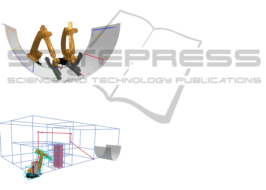
are equipped with special end-effectors to handle dry
fibre textiles. The half cylinder shows the lower half
of a fuselage. The colourful outlines show the plac-
ing position for the fibre cut pieces. Figure 6 shows
the path planning for a single robot process in the
CoCo simulation framework. On the left side an in-
dustrial robot can be seen. Each link is surrounded
by a bounding box for collision checking. The red
box in the middle represents an obstacle in the pro-
cess. The grey half cylinder represent the destination.
In this scene the shortest TCP path is calculated with
cell decomposition.
Figure 5: Cooperating robots in CoCo simulation frame-
work putting a dry fibre cut piece in the lower half of a
fuselage.
Figure 6: Path planning for a single robot with the CoCo
simulation framework. The red box represents an obsta-
cle. The blue lines show the cell decomposition of the
workspace and the red line shows one possible path of the
TCP from the actual position of the robot to the lay up po-
sition.
5 EXPECTED OUTCOME
For a CFRP process the state-of-the art cooperating
teaching methods are not suitable. There is the need
for an economic possibility to generate robot pro-
grams to produce high quality CFRP parts. To achieve
that cooperating robots should work more material
based. The normal master-slave control mode which
is state of the art is not satisfactory. The objective
of that thesis is to develop a system which allows
the collisions free path planning for cooperating in-
dustrial robots in the CFRP airplane production. For
the system come into operation methods of computa-
tional intelligence to which belong fuzzy-logic, artifi-
cial neural networks and evolutionary computing.
6 CONCLUSION
In industrial environment where many robots share
the same workspace it is essential to find feasible, col-
lision free paths for the robots. As already shown by
other authors computational intelligence methods are
appropriate for the path planning of single robots. For
cooperating robots the collision free path planning is
even more complex. However here computational in-
telligence methods are very promising candidates for
the planning.
REFERENCES
Ali, M. S. A. D., Babu, N. R., Varghese, K., Engg, C., and
Madras, I. I. T. (2002). Offline path planning of co-
operative manipulators using co-evolutionary genetic
algorithms. ISARC.
Baraff, D. (2001). Physically Based Modeling: Rigid Body
Simulation. Technical report.
Barraquand, J., Langlas, B., and Latombe, J. C. (1992).
Numerical Potential Field Techniques for Robot Path
Planning. 22:224–241.
Bradshaw, G. and O’Sullivan, C. (2004). Adaptive Medial-
Axis Approximation for Sphere-Tree Construction.
ACM Transactions on Graphics, 23:1–26.
Cameron, S. (1997). Enhancing GJK: Computing Min-
imum and Penetration Distances between Convex
Polyhedra. In Proceedings of International Confer-
ence on Robotics and Automation, pages 3112–3117.
Cheng, H. H. (1995). Real-time four-dimensional Collision
Detection for an Industrial Robot Manipulator.
Craig, J. J. (2005). Introduction to Robotics.
Cueva, V. D. and Ramos, F. (2002). Adapting the Messy Ge-
netic Algorithm for Path Planning in Redundant and
Non-redundant Manipulators. (1):21–30.
Curkovic, P., Jerbic, B., and Stipancic, T. (2013). Co-
Evolutionary Algorithm for Motion Planning of Two
Industrial Robots with Overlapping Workspaces. In-
ternational Journal of Advanced Robotic Systems,
page 1.
Daily, R. and Bevly, D. M. (2008). Harmonic Potential
Field Path Planning for High Speed Vehicles. In
American Control Conference, pages 4609–4614.
Eberhart, R. C. and Shi, Y. (2007). Computational Intelli-
gence Concepts to Implementations.
Ehmann, S. A. and Lin, M. C. (2000). SWIFT: Accelerated
Proximity Queries Using Multi-Level Voronoi March-
ing.
IntelligentPathPanningTowardsCollision-freeCooperatingIndustrialRobots
45

Fawaz, K., Merzouki, R., and Ould-Bouamama, B. (2009).
Model Based Real Time Monitoring for Collision
Detection of an Industrial Robot. Mechatronics,
19(5):695 – 704.
Figueiredo, M., Oliveira, J., Araujo, B., and Pereira, J.
(2006). An Efficient Collision Detection Algorithm
for Point Cloud Models. Technical report.
Garg, D. P. and Kumar, M. (2002). Optimization techniques
applied to multiple manipulators for path planning and
torque minimization. Engineering Applications of Ar-
tificial Intelligence, 15(3-4):241–252.
Gilbert, E. G. (1988). A Fast Procedure for Computing
the Distance Between Objects in Three-Dimensional
Space. Technical report.
Gilbert, E. G. and Foo, C. P. (1990). Computing the
Distance Between General Convex Objects in Three-
Dimensional Space. IEEE Transactions on Robotics
and Automation, 6(1):53–61.
Gosselinj, C. (1994). Robot Path Planning Using Neural
Networks and Fuzzy Logic. (418).
Heidelberger, B. (2004). Detection of Collisions and Self-
collisions Using Image-space Techniques. Journal of
WSCG, 12(3):145–152.
Heidelberger, B., Teschner, M., and Gross, M. (2003). Vol-
umetric Collision Detection for Deformable Objects.
Technical report.
Hermann, A. (2013). GPU-based real-time collision de-
tection for motion execution in mobile manipulation
planning. Advanced Robotics (ICAR), 2013 16th In-
ternational Conference on.
Huang, S.-j. and Lian, R.-j. (1997). A hybrid fuzzy logic
and neural network algorithm for robot motion con-
trol. IEEE Transactions on Industrial Electronics,
44(3):408–417.
Jang, H.-Y. (2006). GPU-based Image-space Approach to
Collision Detection among Closed Objects.
Jang, H.-Y., Jeong, T., and Han, J. (2007). Image-space
Collision Detection Through Alternate Surface Peel-
ing. In Proceedings of the 3rd international confer-
ence on Advances in visual computing - Volume Part I,
ISVC’07, pages 66–75, Berlin, Heidelberg. Springer-
Verlag.
Juan C. Fraile, M. M. and Dodds, G. I. (1999). Optimiza-
tion of Collision Free Trajectories in Multi-Robot Sys-
tems.
Kazem, B. I., Mahdi, A. I., and Oudah, A. T. (2008). Mo-
tion Planning for a Robot Arm by Using Genetic Al-
gorithm. 2(3):131–136.
Kitamura, Y., Tanaka, T., Kishino, F., and Yachida, M.
(1995). 3-D Path Planning in a Dynamic Environ-
ment Using an Octree and an Artificial Potential Field.
Technical report.
Klanke, S., Lebedev, D., Haschke, R., Steil, J., and Ritter,
H. (2006). Dynamic Path Planning for a 7-DOF Robot
Arm. 2006 IEEE/RSJ International Conference on In-
telligent Robots and Systems, (i):3879–3884.
Klein, J. and Zachmann, G. (2004). Point Cloud Collision
Detection. In Cani, M.-P. and Slater, M., editors, Com-
puter Graphics forum (Proc. EUROGRAPHICS), vol-
ume 23, pages 567–576, Grenoble, France.
Kockara, S., Halic, T., K.Iqbal, Bayrak, C., and Rowe, R.
(2007). Collision detection: A survey. Technical re-
port.
LaValle, S. M. (2006). Planning Algorithms. Cambridge
University Press, Cambridge.
Lebedev, D. V., Steil, J. J., and Ritter, H. J. (2005). The
dynamic wave expansion neural network model for
robot motion planning in time-varying environments.
49(0):1–50.
Li, S., Chen, S., Liu, B., Li, Y., and Liang, Y. (2012). De-
centralized kinematic control of a class of collabora-
tive redundant manipulators via recurrent neural net-
works. Neurocomputing, 91:1–10.
Lin, M. C. and Canny, J. F. (1991). A Fast Algorithm for
Incremental Distance Calculation. In In IEEE Interna-
tional Conference on Robotics and Automation, pages
1008–1014.
Lin, M. C. and Manocha, D. (1993). Efficient Contact De-
termination Between Geometric Models. Technical
report, International Journal of Computational Geom-
etry And Applications.
Mirtich, B. V. (1996). Impulse-based Dynamic Simulation
of Rigid Body Systems. PhD thesis. AAI9723116.
Mirtich, B. V. (1998). V-Clip: fast and robust polyhedral
collision detection. ACM Trans. Graph., 17(3):177–
208.
Moore, M. and Wilhelms, J. (1988). Collision Detection
and Response for Computer Animation. In Computer
Graphics, pages 289–298.
Myszkowski, K., Okunev, O. G., and Kunii, T. L. (1995).
Fast Collision Detection Between Complex Solids Us-
ing Rasterizing Graphics Hardware. The Visual Com-
puter, 11(9):497–511.
Pan, J., Chitta, S., and Manocha, D. (2011). Probabilistic
Collision Detection Between Noisy Point Clouds Us-
ing Robust Classification. In International Symposium
on Robotics Research, Flagstaff, Arizona.
Pedrocchi, N., Malosio, M., and Tosatti, L. M. (2009). Safe
Obstacle Avoidance for Industrial Robot Working
Without Fences. In Proceedings of the 2009 IEEE/RSJ
international conference on Intelligent robots and sys-
tems, IROS’09, pages 3435–3440, Piscataway, NJ,
USA. IEEE Press.
Saravanan, R., Ramabalan, S., and Balamurugan, C. (2007).
Evolutionary optimal trajectory planning for indus-
trial robot with payload constraints. The Interna-
tional Journal of Advanced Manufacturing Technol-
ogy, 38(11-12):1213–1226.
Scott, D. S. and Vuillemin, J. (1986). Art Gallery Theorems
and Algorithms.
Stewart, N. T. (2008). An Image-Space Algorithm for
Hardware-based Rendering of Constructive Solid Ge-
ometry - (1).
Stroulia, E., Schneider, D., and Prassler, E. (1997). Pur-
poseful and Reactive Navigation Based on 9 Qualita-
tive Path Planning and Fuzzy Logic.
Tang, L., Dian, S., Gu, G., Zhou, K., Wang, S., and Feng,
X. (2010). A Novel Potential Field Method for Obsta-
cle Avoidance and Path Planning of Mobile Robots.
Technical report.
ICINCO2014-DoctoralConsortium
46

Ting, Y., Lei, W., and Jar, H. (2002). A path planning al-
gorithm for industrial robots. Computers & Industrial
Engineering, 42(2-4):299–308.
Tzafestas, C. S., Prokopiou, P. A., and Tzafestas, S. G.
(1998). Path Planning and Control of a Coopera-
tive Three-Robot System Manipulating Large Objects.
pages 99–116.
van den Bergen, G. (1999). A Fast and Robust GJK Imple-
mentation for Collision Detection of Convex Objects.
J. Graph. Tools, 4(2):7–25.
van den Bergen, G. (2001). Proximity Queries and Penetra-
tion Depth Computation on 3D Game Objects. In Pro-
ceedings of Game Developers Conference 2001, San
Jose, CA.
Yakut, I. D. (2010). Collision Detection of Multiple Moving
Objects on GPU. Technical report.
Zavlangas, P. G. and Tzafestas, S. G. (2000). Industrial
Robot Navigation and Obstacle Avoidance Employing
Fuzzy Logic. pages 85–97.
IntelligentPathPanningTowardsCollision-freeCooperatingIndustrialRobots
47
