
Integrated Simulation of
Implantable Cardiac Pacemaker Software and Heart Models
Cinzia Bernardeschi
1
, Andrea Domenici
1
and Paolo Masci
2
1
Department of Information Engineering, University of Pisa, Pisa, Italy
2
School of Electronic Engineering and Computer Science (EECS), Queen Mary University of London, London, U.K.
Keywords:
Public Health Informatics, Software Analysis, Formal Verification Technologies.
Abstract:
This paper presents an approach for integrated simulation of pacemaker models and heart models, each de-
veloped with the appropriate formalism. Heart models are developed in MathWorks, a powerful tool for the
simulation of complex systems, whereas pacemakers are developed in PVS, a theorem-proving environment
enabling both simulation and formal verification of safety requirements. The two tools communicate over a
Web-based interface, which makes it possible to integrate the simulation of the MathWorks model of the heart
and the PVS model of the pacemaker. In this paper, we illustrate the architecture developed for integrated
simulation of the pacemaker-heart system and present an example application for realistic models.
1 INTRODUCTION
Software incorporated in pacemakers must be demon-
strably safe and effective. To this aim, software engi-
neers need to resolve two different challenges:
1. Make sure that the software is exempt from design
errors, such as deadlocks.
2. Make sure that software behaviour correctly in-
corporates medical-domain specific knowledge,
such as how the pacing technique should adapt to
the patient’s conditions.
To address the first concern, software engineers
can create mathematical models of the software, use
verification tools such as model-checkers and theo-
rem provers to analyse all software behaviours de-
scribed in the models, and then generate pacemaker
code from the verified models using automatic code-
transformation techniques. Techniques for addressing
this concern are overviewed in (Jiang et al., 2012b).
To address the second concern, on the other hand,
software engineers need to engage with medical-
domain experts. This is usually done by creating re-
alistic simulations that demonstrate the software be-
haviour and the hypotheses under which the software
has been verified. This concern is key to deliver a bet-
ter quality of life to patients. In this work, we focus
on this second concern.
1.1 Problem Statement
Pacemaker software is usually analysed using tools
that enable the analysis of safety requirements, such
as UPPAAL (Behrmann et al., 2006) or PVS (Owre
et al., 1996). Sophisticated heart models, on the other
hand, are usually developed in MathWorks, which of-
fers a modelling language more appropriate for phys-
iological systems. Software engineers would benefit
from using all above tools in combination – each part
of the system could be modelled using the most ap-
propriate tool. In reality, however, the above tools
are not interoperable. To simulate the whole sys-
tem, models need to be translated, as each model
can be executed only in its native simulation environ-
ment. This is, however, not always feasible, e.g., be-
cause environments like MathWorks use proprietary
languages (Hamon and Rushby, 2004), or convenient,
e.g., because a single modelling environment does not
fit all analysis needs.
1.2 Contribution
An approach is presented for integrated simulation
of pacemaker models developed in PVS and heart
models developed in MathWorks without the need
of model translation. The approach uses two web-
services, ICP-web and heart-web, to intercept relevant
simulation events, and forward them from one simu-
lation environment to the other (Figure 1).
55
Domenici A., Bernardeschi C. and Masci P..
Integrated Simulation of Implantable Cardiac Pacemaker Software and Heart Models.
DOI: 10.5220/0005153900550059
In Proceedings of the 2nd International Congress on Cardiovascular Technologies (CARDIOTECHNIX-2014), pages 55-59
ISBN: 978-989-758-055-0
Copyright
c
2014 SCITEPRESS (Science and Technology Publications, Lda.)

PVSio
ICP-web
ICP model
web sockets
heart model
heart-web
web socket interface
MathWorks simulation
PVS environment
Figure 1: Integrated simulation approach.
Using this approach, the pacemaker and heart
models can be executed in their native simulation
environments. A demonstration of the approach is
given for a software model of a modern dual chamber
implantable cardiac pacemaker (ICP) and a detailed
model of the heart. A snapshot of an integrated simu-
lation example is in Figure 4.
2 METHODS
Two web-services, ICP-web and heart-web, are used
to integrate PVS simulations of pacemaker software
and MathWorks simulations of the heart (Figure 1):
• ICP-web is linked to the PVSio simulation envi-
ronment of PVS. It uses a socket connection to re-
ceive events (atrial and ventricular signals) from
the heart model. The events are transmitted to the
ICP simulation. The same socket connection is
used to send pacing events generated by the ICP
simulation to the heart simulation.
• Heart-web is linked to MathWorks. It receives
pacing events over a socket connection with ICP-
web. The events are injected in the heart simula-
tion. Atrial and ventricular events from the heart
simulation are sent to the ICP simulation using the
same socket connection.
The above approach builds on and extends the
framework presented in (Masci et al., 2014) for inte-
grated simulation of PVS models and Stateflow mod-
els. In that work, we used web-services to generate
infusion pump simulations, where the user interface
component is developed in PVS, and the pump con-
troller is developed in Stateflow.
2.1 Pacemaker Model in PVS
Pacemaker software is usually modelled with timed
automata (TA) (Alur and Dill, 1994). TAs operate in
a number of distinct modes, switching between them
when certain events occur. While the system remains
in a given mode, its state is givenby the values of state
variables, representing the program variables used by
the pacemaker software. Each TA has a unique initial
state, modelling the initial value of program variables.
LRI
t <= TLRI − TAVI
AS
VP / t:=0
VS / t:=0
[t >= TLRI−TAVI] AP / t:= 0
Ased
VP / t:=0
VS / t:=0
Figure 2: A timed automaton modelling the behaviour of a
pacemaker software routine.
Figure 2 (adapted from (Jiang et al., 2012b))
shows an example of TA model. It defines the be-
haviour of the Lower Rate Interval routine of an ICP
software, responsible for keeping the heart rate above
a minimum value. The TA remains in the initial mode
LRI at most TLRI− TAVI milliseconds, where TLRI
and TAVI are the periods of the Lower Rate Interval
and Atrio-Ventricular Interval of the cardiac cycle.
Transitions are labelled by actions (AS, AP, VS,
VP), guards (in square brackets), and clock assign-
ments (denoted by ‘
:=
’). The actions represent occur-
rences of the events Atrial Sense, Atrial Pulse, Ven-
tricular Sense, and Ventricular Pulse, respectively.
Three transitions, labelled with actions VS, VP, and
AP, leave the automaton in mode LRI and reset clock
t. Transition AS, on the other hand, brings the au-
tomaton from mode LRI to mode Ased. From the lat-
ter, transitions labelled with VS and VP bring the au-
tomaton back to LRI, resetting the clock. The transi-
tion guards specify the conditions under which a tran-
sition may occur. For example, transition AP may oc-
cur only if the guard t ≥ TLRI− TAVI is satisfied.
Within the PVS verification system, TAs are spec-
ified using higher-order logic:
• The state of the automaton is defined by a record
type representing the mode, plus one real-valued
variable for each clock. One record field, time,
represents the global time.
• For each transition τ, (i) a transition function re-
turns the next state as a function of the current
state, and (ii) a permission predicate specifies the
states where τ is allowed, and its guard.
• A time advancement function updates time.
The following PVS fragment shows part of the PVS
model for the TA of Figure 2:
Mode: TYPE = { LRI, Ased }
state: TYPE = [# time: real, mode: Mode #]
per_APout(st: state): boolean =
mode(st) = LRI AND time(st) >= TLRI-TAVI
APout(st: (per_APout)): state =
(# time := 0, mode := LRI #)
The first two lines define the set of modes and the
structure of the state record, containing the mode and
time variables. Functions per
APout and APout are
the permission predicate and the transition function,
CARDIOTECHNIX2014-InternationalCongressonCardiovascularTechnologies
56

respectively, of the transition labelled with AP. The
complete PVS model of the ICP is in a technical re-
port (Masci P. et al., 2014).
The PVS is an interactive environment, wherein
a user proves a logical statement by manipulating it
with commands provided by the environment. For ex-
ample, the following statement can be proved with a
single command:
lri_ap: LEMMA
FORALL (s0, s1: State):
per_APout(lri(s0)) AND s1 = APout(s0)
IMPLIES
mode(lri(s1)) = LRI AND time(lri(s1)) = 0
The above lemma means: “It is always the case that
module lri is in mode LRI and its clock is reset when
transition AP is executed.” Lemmas like this allow us
to perform essential sanity checks for the model, and
verify that the model definition correctly incorporates
hypotheses about the behaviour of the system. In our
case, an attempt to prove this lemma on an early ver-
sion of the model failed, leading us to the discovery
of an error in another part of the specification.
2.2 MathWorks Model of the Heart
Heart models are generally built using hybrid au-
tomata (HA) (Henzinger, 1996). Also HAs are char-
acterised by different modes of operation. However,
differently from TAs, in each mode their state varies
continuously with time according to some mathemat-
ical law, e.g., a differential equation. In different
modes, the state may follow different laws.
In this paper, we use the Simulink model devel-
oped by Chen et al. in (Chen et al., 2014). In their
model, the heart’s electrical conduction system is
specified as a network of HAs implemented in Math-
Works/Simulink. The HAs representing ventricular
cells have four modes: resting and final repolariza-
tion, stimulation, upstroke, and plateau and early re-
polarization. In each mode, the membrane voltage
follows a specific differential equation. The com-
plete MathWorks/Simulink model consists of over
200 functional blocks. A detailed illustration of the
model is in (Chen et al., 2014). Here, we illustrate the
overall architecture and the input and output parame-
ters of the model, as this is sufficient for the scope of
this work.
The heart model has two main functional modules,
Atrium
and
Ventricle
, representing the electrical
behaviour of the atrium and ventricle (see Figure 3).
The two modules communicate through an
AV
mod-
ule, which represents the AV node of the heart. Two
input parameters allow designers to inject pacemaker
signals in the heart: AP (Atrial Pacing), is used to in-
ject the pacing stimulus generated by the pacemaker
Figure 3: Architecture of the heart model.
in the atrium; VP (Ventricle Pacing), is used to in-
ject the pacing stimulus generated by the pacemaker
in the ventricle. Another input, sasignal (Sinoatrial
node signal), represents the firing frequency of the
impulse-generating tissue of the heart. This input can
be used to change the heart behaviour and explore dif-
ferent scenarios (e.g., normal sinus rhythm, bradycar-
dia, tachycardia). Two output parameters, Abeat and
Vbeat, are used to check whether the electric signal
from the atrium and the ventricle has reached given
thresholds.
3 RESULTS
To demonstrate the integrated simulation approach,
we consider a pacemaker model and a heart model
independently developed by two research groups.
The pacemaker model describes the behaviour of
software used in modern dual-chamber ICPs (Jiang
et al., 2012b). It is a network of five automata, each
managing a specific aspect of the cardiac cycle: the
Lower Rate Interval, the Upper Rate Interval, the
Atrio-Ventricular Interval, the Post Ventricular Atrial
Refractory Period, and the Ventricular Refractory Pe-
riod. The state of the system is given by the union of
the component states. This model has been translated
into the PVS language as outlined in Section 2.1. The
translated model was then interfaced to the ICP-web
service using our PVSio-web tool (Oladimeji et al.,
2013), which creates the communication infrastruc-
ture to support the exchange of simulation events be-
tween PVS and MathWorks/Simulink.
The heart model is a realistic model devel-
oped in MathWorks/Simulink. The model was
presented by others in (Chen et al., 2014).
We interfaced this model to the heart-web ser-
vice by adding a communication interface mod-
ule (block
heart webservice interface
in the
Simulink model in Figure 4). This communica-
tion module enables seamless exchange of simulation
events with the pacemaker: (i) pacemaker signals AP
and VP received from the pacemaker simulation are
injected in the heart model; (ii) heart signals Abeat
and Vbeat are intercepted and forwarded them to the
IntegratedSimulationofImplantableCardiacPacemakerSoftwareandHeartModels
57
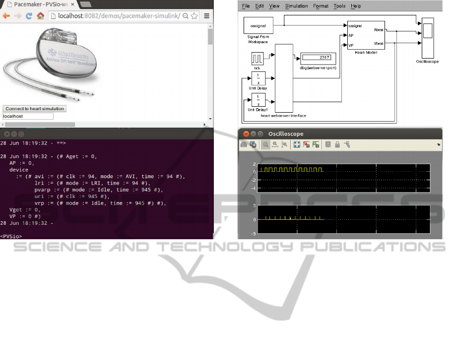
(a) PVSio simulation of the ICP model. (b) MathWorks simulation of the heart model.
Figure 4: Example of integrated simulation.
(# Aget := 0,
AP := 0,
device
:= (# avi := (# clk := 94, mode := AVI, time := 94 #),
lri := (# mode := LRI, time := 94 #),
pvarp := (# mode := Idle, time := 945 #),
uri := (# clk := 945 #),
vrp := (# mode := Idle, time := 945 #),
Vget := 0,
VP := 0 #)
Figure 5: PVS state of the ICP model of Figure 4(a).
pacemaker simulation.
Screenshots from an integrated simulation exam-
ple are in Figure 4 (the specific parameters used in the
simulation are not relevant for sake of this example):
• The PVS simulation of ICP model is in Fig-
ure 4(a). The screenshot at the top is the browser
interface we use for setting up and start the ICP-
web service. The one at the bottom is the cur-
rent state of the PVS model during the simulation
(reproduced for convenience in Figure 5). In the
state, field
device
holds the state of the pace-
maker software modules, while the other fields
(
Aget
,
Vget
,
AP
,
VP
) are auxiliary variables for
storing input and output signals of the pacemaker.
• The MathWorks/Simulink simulation of the heart
model is in Figure 4(b). The screenshot at the top
is the heart model interfaced with the heart-web
service and with an oscilloscope for rendering the
input stimulus
sasignal
and information about
atrial and ventricular signals. An example of os-
cilloscope output during a simulation is at the bot-
tom of the figure.
4 RELATED WORK
Formal verification and validation of the whole
pacemaker-heart system has been explored in several
papers using multiple analysis tools and modelling
formalisms.
For example, in (Jiang et al., 2010) and (Jiang
et al., 2012a), a pacemaker-heart system is verified
and validated using MathWorks/Simulink and UP-
PAAL (Behrmann et al., 2006). The former is used
for realistic simulations, the latter is used to verify
safety requirements of the pacemaker-heart system
CARDIOTECHNIX2014-InternationalCongressonCardiovascularTechnologies
58

using formal methods technologies. Ad hoc models
are developed in UPPAAL to translate core parts of
the Simulink models needed for the verification.
Similarly, in (Chen et al., 2014), Math-
Works/Simulink is used in conjunction with
Prism (Kwiatkowska et al., 2011). Ad hoc Prism
models are developed that represent the behaviour of
the pacemaker-heart system and verify pacemaker
properties related to energy consumption.
Differently from the above works, our approach
alleviates the problem of developing and maintain-
ing multiple models by enabling integrated simu-
lation. We demonstrated the approach for Math-
Works/Simulink and PVS, but the approach is gen-
eral and can be used to enable integrated execution of
simulations for other analysis environments.
5 CONCLUSIONS
The construction of a formal model of the device and
the application of formal verification techniques can
help to prove that the device performs the required
functions under all the stated conditions, thus enhanc-
ing patient safety.
We developed a framework that makes possi-
ble both the simulation of the device in conjunction
with Simulink heart models built on medical domain-
specific knowledge, and the verification of invariants
of the device through the theorem proving approach.
In this way, system designers may use simulation re-
sults to validate the system behaviour with the guid-
ance of domain experts, and formal verification to en-
sure the correctness of its design.
Integrated simulation allows software engineers to
demonstrate the functionalities of the pacemaker soft-
ware, and discuss hypotheses about its behaviour for
different physiological parameters of the patient. On
the other hand, the correctness of the pacemaker de-
sign can be formally checked by assume-guarantee
reasoning (Henzinger et al., 2001), i.e., by proving
that the ICP guarantees the desired behaviour of the
ICP-heart system under suitable assumptions on the
heart model. Formalising these assumptions will be
the object of further work.
ACKNOWLEDGEMENTS
We would like to thank Alexandru Mereacre (Uni-
versity of Oxford), who helped us with the
MathWorks/Simulink model of the heart. This
work is supported by EPSRC through CHI+MED
(EP/G059063/1, http://www.chi-med.ac.uk).
REFERENCES
Alur, R. and Dill, D. L. (1994). A theory of timed automata.
Theoretical Computer Science, 126(2):183–235.
Behrmann, G., David, A., Larsen, K., Hakansson, J., Pet-
terson, P., Yi, W., and Hendriks, M. (2006). UPPAAL
4.0. In Third Int. Conf. on Quantitative Evaluation of
Systems (QEST 2006), pages 125–126.
Chen, T., Diciolla, M., Kwiatkowska, M., and Mereacre, A.
(2014). Quantitative verification of implantable car-
diac pacemakers over hybrid heart models. Informa-
tion and Computation, 236(0):87–101.
Hamon, G. and Rushby, J. (2004). An operational semantics
for Stateflow. InFundamental Approaches to Software
Engineering (FASE), volume 2984 of LNCS, pages
229–243. Springer Berlin Heidelberg.
Henzinger, T. A. (1996). The theory of hybrid automata. In
Proc. of the 11th Annual IEEE Symposium on Logic in
Computer Science, LICS ’96, pages 278–292, Wash-
ington, DC, USA. IEEE Computer Society.
Henzinger, T. A., Minea, M., and Prabhu, V. S. (2001).
Assume-guarantee reasoning for hierarchical hybrid
systems. In Benedetto, M. D. D. and Sangiovanni-
Vincentelli, A. L., editors, HSCC, volume 2034 of
LNCS, pages 275–290. Springer.
Jiang, Z., Pajic, M., Connolly, A., Dixit, S., and Mang-
haram, R. (2010). Real-time heart model for im-
plantable cardiac device validation and verification.
In Real-Time Systems (ECRTS), 2010 22nd Euromicro
Conference on, pages 239–248. IEEE.
Jiang, Z., Pajic, M., and Mangharam, R. (2012a). Cyber–
physical modeling of implantable cardiac medical de-
vices. Proc. of the IEEE, 100(1):122–137.
Jiang, Z., Pajic, M., Moarref, S., Alur, R., and Mang-
haram, R. (2012b). Modeling and verification of a
dual chamber implantable pacemaker. In Flanagan, C.
and K¨onig, B., editors, Tools and Algorithms for the
Construction and Analysis of Systems, volume 7214
of LNCS, pages 188–203. Springer Berlin Heidelberg.
Kwiatkowska, M., Norman, G., and Parker, D. (2011).
Prism 4.0: Verification of probabilistic real-time sys-
tems. In Computer aided verification, pages 585–591.
Springer.
Masci, P., Zhang, Y., Jones, P., Oladimeji, P., D’Urso,
E., Bernardeschi, C., Curzon, P., and Thimbleby,
H. (2014). Combining PVSio with stateflow. In
Proc. of the 6th NASA Formal Methods Symposium
(NFM2014), Berlin, Heidelberg. Springer-Verlag.
Masci P. et al. (2014). Modelling a dual chamber im-
plantable cardiac pacemaker in PVS. Technical report,
Queen Mary University of London.
Oladimeji, P., Masci, P., Curzon, P., and Thimbleby, H.
(2013). PVSio-web: a tool for rapid prototyping de-
vice user interfaces in PVS. In FMIS2013, 5th Int.
Workshop on Formal Methods for Interactive Systems.
Owre, S., Rajan, S., Rushby, J., Shankar, N., and Srivas, M.
(1996). PVS: combining specification, proof check-
ing, and model checking. In Alur, R. and Henzinger,
T. A., editors, Computer-Aided Verification, CAV ’96,
number 1102 in LNCS, pages 411–414.
IntegratedSimulationofImplantableCardiacPacemakerSoftwareandHeartModels
59
