Study of an EEG based Brain Machine Interface System
for Controlling a Robotic Arm
Yicong Gong, Carly Gross, David Fan, Ahmed Nasrallah, Nathaniel Maas,
Kelly Cashion and Vijayan K. Asari
Department of Electrical and Computer Engineering, University of Dayton, Dayton, OH 45469, U.S.A.
Keywords: Brain Machine Interface, Robotic Arm, Electroencephalography, Independent Component Analysis.
Abstract: We present a methodology to explore the capabilities of an existing interface for controlling a robotic arm
with information extracted from brainwaves. Brainwaves are collected through the use of an Emotiv EPOC
headset. The headset utilizes electroencephalography (EEG) technology to collect active brain signals. We
employ the Emotiv software suites to classify the thoughts of a subject representing specific actions. The
system then sends an appropriate signal to a robotic interface to control the robotic arm. We identified
several actions for mapping, implemented these chosen actions, and evaluated the system’s performance.
We also present the limitations of the proposed system and provide groundwork for future research.
1 INTRODUCTION
The term Brain Machine Interface (BMI) refers to a
system which uses sensors to collect data from the
brain, classifies the data, and encodes the data as
control signals for a computer or machine (Shenoy,
2006). At the beginning of this research project, we
started with an existing BMI system (Ouyang, 2013).
This uses an affordable Emotiv electroence-
phalograph (EEG) headset to interface with and
control a 7 degrees of freedom (DoF) robotic arm,
the Robai Cyton Veta.
The raw EEG data collected through the 14
electrode headset is analyzed and used to signal the
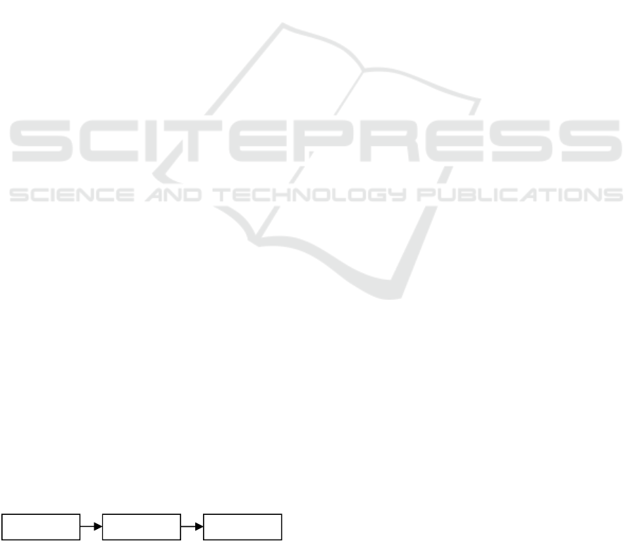
robot to execute commands. Figure 1 below
illustrates a current BMI system, and the process
used to encode the action.
Figure 1: The 3 Phase BMI System.
The goals of this research project, beyond
refining the system, are as follows: to test different
thought patterns and determine the best method of
creating and detecting unique brainwave signatures,
to create a universal profile (one folder containing
several subjects’ data) and test this against the
individual subject’s folder, and to examine the
feasibility of using pure EEG data in conjunction
with facial expressions, which create
electromyography (EMG) and electrooculography
(EOG) signals (Baztarrica, 2002).
2 INTERFACE CRITERIA
A sequence of actions selected from the pool of
available commands are generated randomly. For
each set of trials, a maximum number of attempts
are set to prevent the user from attempting an
unlimited number of trials. The maximum number of
attempts is determined to be at least double the
length of the sequence to ensure a consistent
accuracy.
To test the system the following test plan was
executed for each trial:
1. Train the neutral state and train actions 5 times
2. Each tested user performs the following for
both the personal profile and universal profile:
- The test subject attempts to execute an action
- The test subject stops attempting to execute the
action once the robot has started moving
- The output of EmoKey is be recorded
- The output of the robot console which displays
executed actions will be recorded
- The previous 3 steps are repeated for each
action until there are no more actions remaining or
until the maximum numbers of attempts is reached
In this experiment, four different trials were
Encoding
Processing Controlling
339
Gong Y., Gross C., Fan D., Nasrallah A., Maas N., Cashion K. and K. Asari V..
Study of an EEG based Brain Machine Interface System for Controlling a Robotic Arm.
DOI: 10.5220/0005157803390344
In Proceedings of the International Conference on Neural Computation Theory and Applications (NCTA-2014), pages 339-344
ISBN: 978-989-758-054-3
Copyright
c
2014 SCITEPRESS (Science and Technology Publications, Lda.)
tested. The difficulty of each trial is increased by
adding more actions to the trial and thereby
decreasing the accuracy. The first trial tests two
individual EEG actions, Left (L) and Right (R), in
the sequence LRRL with a maximum of 9 attempts.
The second trial repeats the first trial test but aids the
Left and Right actions by clenching the appropriate
fist to test the impact of the cognitive execution
physical actions on EEG signals. The third trial adds
two more actions, Smirking Left (A) and Smirking
Right (B), to the first trial test in the sequence of
BLABRA with a maximum of 12 attempts. The final
trial tests a total of seven actions by adding three
additional actions, Winking Left (X), Jaw Clenching
(J), and Raising Eyebrows (W), to trial three in the
sequence of LJWBABRLRXAJXW with a
maximum of 28 attempts.
In the former BMI system, the robot console
could receive keystrokes from the EmoKey software
during the execution of the previous command.
These extra keystrokes were stored within a buffer
and would be executed after its previous robotic
command was finished. The buffer reduces the
accuracy of the system by storing and later
executing these unintended keystrokes. As an
improvement, a filter is implemented to clear the
console buffer, so the console only reads input from
the headset and implements the action when the last
robotic action is completed. The Microsoft
Windowing API command used was:
FlushConsoleInputBuffer (Handle h);
3 EVALUATION STRATEGY
When testing the design of the system, a user
attempts to execute a specific sequence in a given
order. A user is allowed a maximum number of
attempts for each trial. During testing, the user will
attempt to execute the given sequence and will only
move onto the next action when the current action is
executed properly. The user continues this process
until either he or she has reached the maximum
number of attempts for that trial or has fully
executed the correct sequence. The testing accuracy
is defined as the ratio of the number of actions that
are successfully executed to the number of attempts
that are made to complete a trail.
4 TEST DATA AND RESULTS
Below are the results from the four rounds of testing.
As shown in the following figures, satisfactory
results were achieved in the first round of testing,
and the accuracy lowered as more actions were
added.
Figure 2 below illustrates the first round of
testing which consists of Left and Right actions.
Figure 2: First round of Testing Sequence.
Tables 1 and 2 show the results from the first
round of testing. Table 1 has data for each subject
when they were using the Universal Profile and
Table 2 shows each subject’s accuracy on their own
individual profile. Each separate bar corresponds
with a different subject, and the rightmost bar is the
average of all subject’s results. The number above
the bar shows the percentage accuracy.
Table 1: Universal Profile Results (Left and Right).
Subject 1 2 3 4 5 Average
Accuracy(%) 95 63.45 67.5 100 90 83.19
Table 2: Personal Profile Results (Left and Right).
Subject 1 2 3 4 5 Average
Accuracy (%) 78.3 40.4 41.7 83.3 95 67.75
Figure 3 below illustrates the second round of
testing determined by the team which consists of
Left and Right aided with clenching fists.
Figure 3: Second Round of Testing Sequence.
Figures 3 and 4 show the accuracy results for the
second round of testing. In this set of testing the
subject was instructed to physically clench their
right or left fist when thinking right or left.
Table 3: Universal Profile Results (Left and Right) Aided
with Clenching Fists.
Subject 1 2 3 4 5 Average
Accuracy(%) 90 65.2 81 95 95 85.24
Table 4: Personal Profile (Left and Right) Aided with
Clenching Fists.
Subject 1 2 3 4 5 Average
Accuracy(%) 71.8 51.1 81.7 100 95 79.91
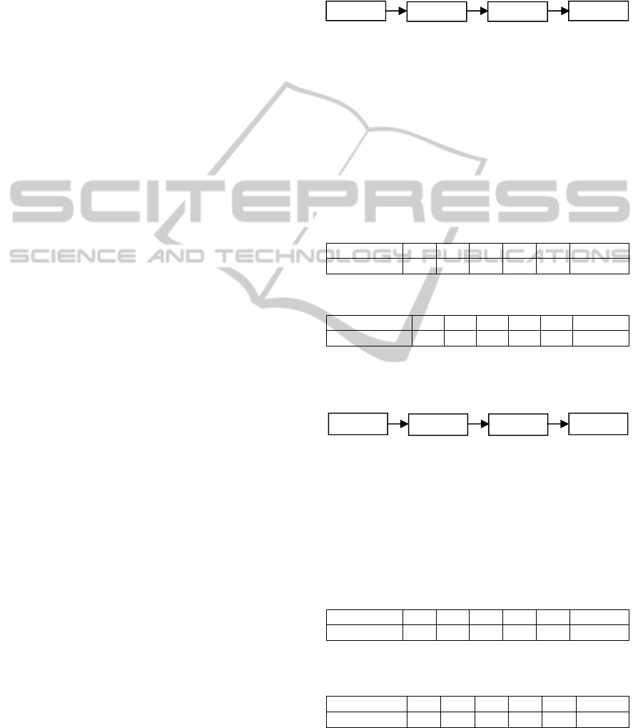
Figure 4 below illustrates the second and third
round of testing determined by the team which
consists of Left, Right, Left Smirk, and Right Smirk.
Left
Right
Right
Left
LeftFist
RightFist
RightFist
LeftFist
NCTA2014-InternationalConferenceonNeuralComputationTheoryandApplications
340
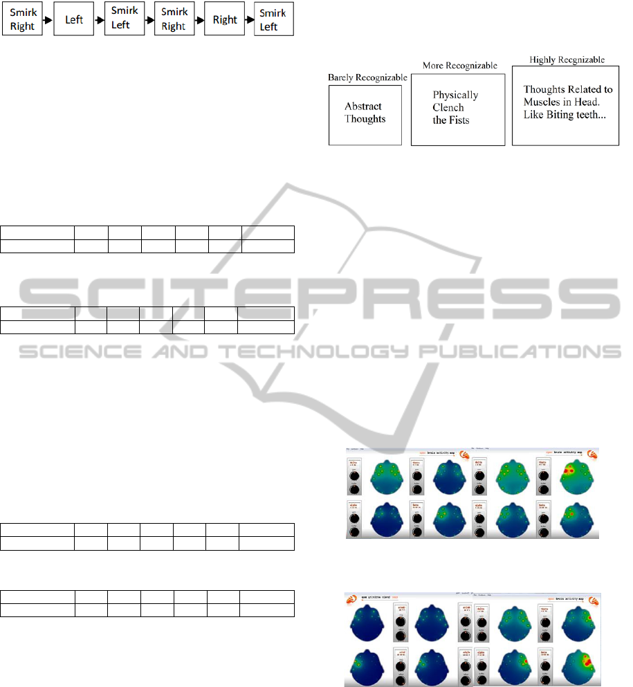
Figure 4: Third Round of Testing Sequence.
Tables 5 and 6 show the results when the users
had a sequence that included left movement, right
movement, and two facial expression actions. This
round of testing also included the implementation of
a filter which caught and discarded superfluous
facial expression signals.
Table 5: Universal Profile Results (Left and Right and
Facial Expressions) with Implemented Filter.
Subject 1 2 3 4 5 Average
Accuracy (%) 18.8 36.6 45.3 50.6 40 38.24
Table 6: Personal Profile Results (Left and Right and
Facial Expressions) with Implemented Filter.
Subject 1 2 3 4 5 Average
Accuracy (%) 42 20.8 31.3 39.6 45.8 35.92
The Sequences of the final round of testing is left,
clenching, raise eyebrows, smirk right, smirk left,
smirk right, right, left, right, looking left, smirk left,
clenching, looking left, and raise eyebrow.
Tables 7 and 8 show the results for the final
round of testing. During this test each user attempted
to perform a sequence with all seven actions. This
included two EEG actions and five facial expression
actions.
Table 7: Universal Results of 7 Actions with Filter.
Subject 1 2 3 4 5 Average
Accuracy (%) 25 32.1 31.3 37.5 35.1 32.2
Table 8: Individual Results of 7 Actions with Filter.
Subject 1 2 3 4 5 Average
Accuracy (%) 34.2 33.9 33 30.4 46 35.5
5 DATA ANALYSIS AND
RECOMMENDATIONS
This section discusses the research findings
concluded from the testing.
5.1 Recognizable and Consistent
Thoughts
From the results of testing, the team hypothesized
that thoughts related to muscle movement are much
more distinguishable than abstract thoughts.
Furthermore, thoughts related to muscle movements
and movements around the head are much more
recognizable than physically clenching the fists. The
comparison can be shown in Figure 5 below.
Figure 5: Thought Classification.
Reasons why thoughts related to muscle
movements are more recognizable can be
summarized as:
A) The thoughts related to the muscle
movements are more consistent. This would mean
that the brain activities of abstract thoughts such as
moving a cube in the user’s mind are not consistent
or not strong enough for the headset to detect. It can
become very difficult for the user to think about an
abstract thought in a consistent way. However the
brain activities caused by muscle movements are
very consistent.
B) By utilizing software called Emotiv Brain
Activity Mapping, the brain activity is shown to be
stronger when using muscle movements rather than
only using pure thoughts.
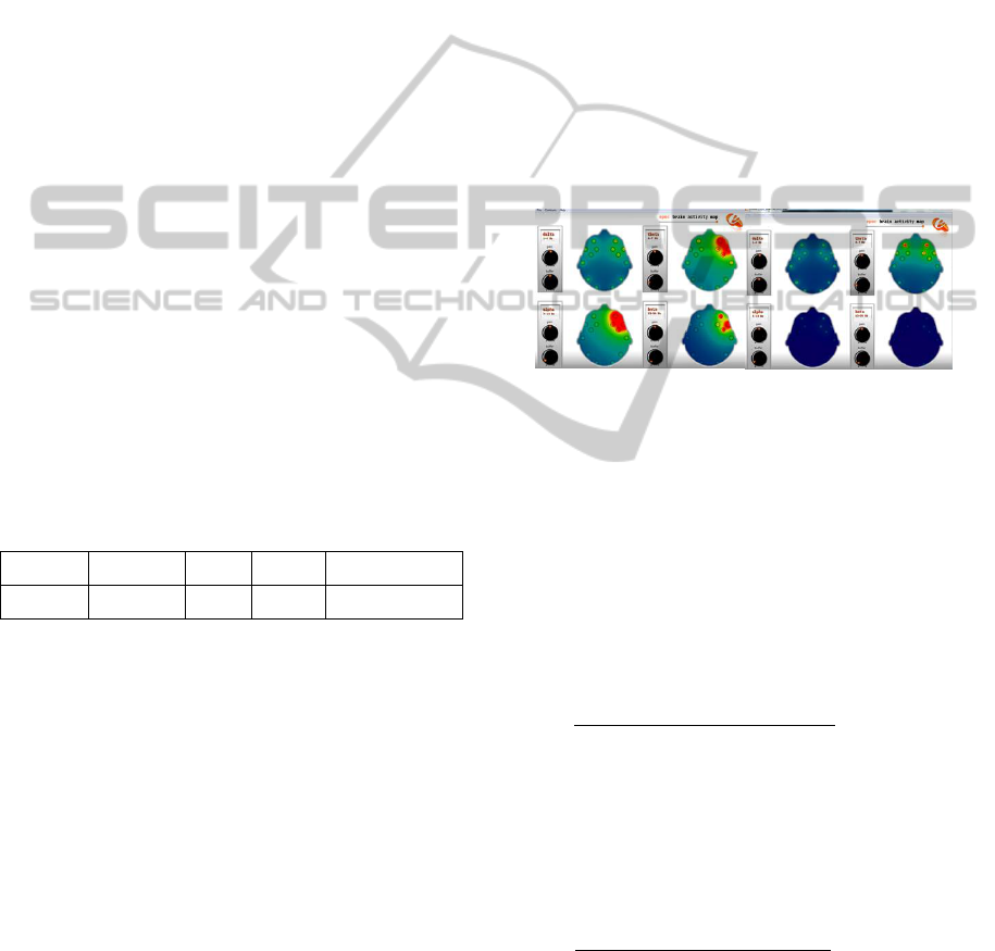
Figure 6: Thinking Left (Left) vs. Left Thinking and
Biting Cheek (Right).
Figure 7: Thinking Right (Up) vs. Right Thinking and
Biting Cheek (Down).
From the figures above, there exists more brain
activity when using muscle movements. This
increased activity is due to the EMG signals that
result from the muscle movement. These are
typically far more distinct than EEG signals, and
have higher amplitudes (Baztarrica, 2002). As a
result, thoughts using facial muscle movements are
more recognizable for the current system.
StudyofanEEGbasedBrainMachineInterfaceSystemforControllingaRoboticArm
341
5.2 Interference between Different
Thoughts
The following are the results of the 4 test trials with
2 aided with physical movement, 2, 4 and 7 thoughts.
Table 9: Accuracy of Universal vs. Individual Profiles.
Number of Commands
Average
Accuracy
(Universal)
Average
Accuracy
(Individual)
2 Thoughts (Pure) 83.19% 67.75%
2 Thoughts
(Aided with Fists)
85.24% 79.91%
4 Thoughts (Cognitive
and Expression)
38.24% 35.92%
7 Thoughts
(Cognitive and
Expression)
32.20% 35.45%
The results shown in Table 1 above, shows a
decrease in accuracy as more commands are
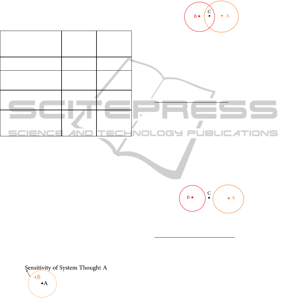
implemented. A modeled setup is created to analyze
this phenomenon. In Figure 8 below, take point A to
be the thought from the profile data saved in the
system (system thought) and point B is the thought
detected from the user (user thought). Let the circle
be the system’s range to match thoughts within its
bounds and the area of the circle will be defined as
the detection sensitivity of the thought. To allow a
uniform range of the system thought with the
sensitivity, point A will be defined as the center of
circle A. The system then needs to match the current
thought, B, to the saved thought, A. Once the user’s
thought is inside the circle, the system will
successfully match the user’s thought to system
thought.
Figure 8: System Thought A and User Thought B.
Now take an implementation of two thoughts as
shown in Figure 9 below. The system thought, A,
will be duplicated into another system thought, B,
contained within its own circle B on the left. If a
user’s thought, C, exists, then there will be a chance
that the user’s thought C happens to occur at the
intersection of Circle A and Circle B. In this case,
the user’s thought can be similar enough to be
matched to both system thought A and system
thought B.
Figure 9: Interference Problem.
As a result, in determining a user’s thought
between two system thoughts, the phenomenon
causes an interference problem. If more thoughts are
implemented, this phenomenon will become more
complex and cause the system's accuracy to drop
rapidly.
Reduced Sensitivity Solution: A solution to the
interference problem is to reduce the range of the
circle for either or both system thoughts A and B
such that no thought interference occurs. This
requires a reduction to the sensitivity of either Circle
A or Circle B or both such that no interference
occurs as shown in Figure 10 below. As a result, a
distinct match of user thought C can be matched to
either system thought A or system thought B without
conflicts. As a result of lowering the sensitivity, it
becomes more difficult for the system to detect a
user’s thought causing the user to think harder.
Figure 10: Reduced Sensitivity Solution.
Dynamic Sensitivity Solution: As discussed
previously, once a user has executed a certain
thought successfully, it is much easier for the user to
think about the same thought than to switch to
another thought or across multiple thoughts.
Referring to figure 20, utilizing this property, we
implemented the following matching algorithm.
Assuming the user’s current thought C resides in
the intersection of A and B.
IF((A is the last thought) AND
(C is contained in A and B))
THEN MATCH C to B;
IF((B is the last thought) AND
(C is contained in A and B))
THEN MATCH C to A;
This solution increases the system’s capacity to
overcome the interference problem without
significantly reducing the sensitivity.
NCTA2014-InternationalConferenceonNeuralComputationTheoryandApplications
342
5.3 Universal User
The results of the 4 test trials with 2, 2, 4 and 7
thoughts shown in testing data and results section
above are compared in Table 1 above.
From the results shown in Table 1, the universal
profile shows higher accuracy than the individual
profile in the majority of the test trials. Since the
subjects in the universal profile tests are using
similar muscle movements to create a specific
brainwave activity, these signals can be considered
to be consistent for different users. This is due to the
brain function to plan and execute these muscle
movements being similar across people (Jasper,
1949). These findings indicate the possibility of
creating a BMI system that can be used by the user
without any training.
5.4 Limitations of the Existing
Software
By comparing the unfiltered input sequences and the
desired input sequences, we discovered that the
Emotiv software handles the pure EEG signals and
facial expressions differently. For example, the
following is a set of data of the unfiltered sequence
and the desired sequences for a test trial.
The sequences and thoughts A, B, L, and R, are
represented in Table 10.
Table 10: Sequences and Actions.
A B L R Desired Sequence
Left Smirk Right Smirk Left Right BLABRA
The System unfiltered input is:
BR...LAAAALAAA...
Examining the two sequences, the user attempts
to obtain a left but he or she obtains a sequence of
LAAAALAAA. Since the left smirk and pure EEG left
thoughts have a significant interference region for
this subject, the user’s thought for pure EEG left is
also matched as a left smirk. The user is attempting
to obtain an L (Pure EEG Left) indicated by the
desired sequence. However, the sequence that the
system reads is LAAALAAA, indicating that the
user had executed more left smirk signals than pure
EEG left signals.
To examine this problem further, we analyzed
the frequency of which the Emotiv software
responds to the given signals and discovered a
potential reason that explained the abundant
matching of facial expressions compared to pure
EEG. In the Emotiv software, detection of facial
expressions and pure EEG signals are concurrent.
However in facial expressions, if a user kept their
facial expression consistent for a period of time,
EmoKey would repeat the keystroke to the robot
control program within that period of time. In
comparison for pure EEG signals, the signaled
keystroke would only be sent at the instant the user
executes a specific thought from the neutral state. A
future recommendation to improve this issue is to
test the facial expression and pure EEG detection
under the same detection system.
5.5 Disturbance Caused by Body
Throughout the test, we discovered that significant
body movements, speaking, or being in an excitingly
emotional state can produce a noisy signal and cause
an unintended action to be performed.
Figure 11: Brain Activity of Random Movement (Left) vs.
No Movement (Right).
In this analysis, a software called Emotiv Brain
Activity Mapping is used to illustrate the brain
activity when executing random body movements as
figure 24. Since the desired system ideally should be
able to function while the user is walking,
emotionally distracted, or even running, the system
should be able to filter out the noisy signals
generated by these movements, or emotional states.
Three possible solutions can be used to help address
this issue.
A) Implementing a Stop Feature: A simple stop
feature would halt the system from executing any
received keystrokes. This feature would also allow
the user to stop or restart the system easily such that
the user will not execute unintended actions while
they are idled from the system. Currently a stop
feature is already implemented in the current state of
the project, but in the future this feature can be
implemented as a facial expression based interface.
B) Sudden Strong Signal Filter: Since subjects
may generate very strong and noisy brain activity
when they are moving, an additional filter is needed
to stop the system from executing actions when it
receives a sudden, strong, and noisy signal. As a
result, this would only allow the system to accept
thoughts while the user is in a calm emotional state.
StudyofanEEGbasedBrainMachineInterfaceSystemforControllingaRoboticArm
343

C) Filter out EMG Noise Signals: Noise filtering
techniques such as independent component analysis
(ICA) can be used to remove specific EEG channels
affected by high amplitude EMG signals for the
duration of the interference (Hyvärinen, 2000). This
would allow the system to continue processing the
pure EEG instead of stop processing altogether.
However, a major challenge is filtering out the
undesired noise while keeping the desired EMG
signals caused by facial expressions being used as
control signals. Filtering out EMG noise would
result in shifting more control commands into the
realm of pure EEG signals, or EEG signals aided
with non-noisy muscle control such as clenching a
fist.
6 CONCLUSIONS
This research project provided a significant amount
of insight into the capabilities of the EEG based
brain machine interface system. We tested different
methods of focusing an individual’s thoughts and the
different methods of signal detections present within
the existing software. Ultimately there were
significant findings about the accuracy of the system.
With minimal actions, the system performed fairly
well. As more actions were added, the system
performance dropped. The universal profile versus
the individual profile also gave a new way of
training the system which examined the idea of more
focused individualization versus a broad wide
sweeping approach. Research work is progressing to
include more actions and activities for building a
full-fledged brain machine interface system.
REFERENCES
Shenoy, Pradeep, Matthias Krauledat, et al. "Towards
adaptive classification for BCI." Journal of Neural
Engineering. 3. (2006): R13-R23. Print.
Ouyang, Wenjia; Cashion, K; Asari, V.K.,
“Electroencephelograph based brain machine interface
for controlling a robotic arm.” (2013). Applied
Imagery Pattern Recognition Workshop: Sensing for
Control and Augmentation. 1-7.
Cunnigham, Patrick; Lang, Keith; Mearn, Brian; Russel,
Lee; and Sanchez, Stephen, “EEG brain-computer
interface project” (2007). Capstone Design Program:
Electrical and Computer Engineering. Paper 2.
Ochoa Jorge Baztarrica, “EEG signal classification for
brain computer interface applications” (2002). Ecole
Polytechnique Federale de Lausanne.
H. Jasper and W. Penfield, “Electrocorticograms in man:
Effects of voluntary movement upon the electrical
activity of the precentral gyrus,” Arch. Psychiat.
Nervenkr., vol. 183, pp. 163–174, 1949.
Hyvärinen and E. Oja. Independent Component Analysis:
Algorithms and Applications. Neural Networks, 13(4-
5):411-430, 2000.
NCTA2014-InternationalConferenceonNeuralComputationTheoryandApplications
344
