
Si elegans
Computational Modelling of C. elegans Nematode Nervous System using FPGAs
Pedro Machado
1
, John Wade
1
and T. M. McGinnity
1,2
1
Intelligent Systems Research Centre (ISRC), University of Ulster, Magee Campus, Derry, Northern Ireland
2
School of Science and Technology, Nottingham Trent University, Nottingham, U.K.
Keywords: Si elegans, Field Programmable Gate Array (FPGA), Hardware Neural Network (HNN), C. elegans,
Wireless Networks, Zigbee.
Abstract: It has long been the goal of computational neuroscientists to understand and harness the parallel
computational power of the mammalian nervous system. However, the vast complexity of such a nervous
system has made it very difficult to fully understand even the most basic of functions such as movement and
learning and accordingly there has been increasing attention paid to the development of emulations of
simpler systems. One such system is the C. elegans nematode, which has been widely studied in recent
years and there now exists a vast wealth of biological knowledge about its nervous structure, function and
connectivity. The Si elegans EU FP7 project aims to develop a Hardware Neural Network (HNN) to
accurately replicate the C. elegans nervous system behaviour to enable neuroscientists to better understand
these basic functions. To fully replicate the C. elegans biological system requires powerful computing
technologies, based on parallel processing, for real-time computation and therefore will use Field
Programmable Gate Arrays (FPGAs) to achieve this. In this paper an overview of the complete hardware
system required to fully realise Si elegans is presented along with an early small scale implementation of the
hardware system.
1 INTRODUCTION
The Si elegans project aims to develop a high
performance computational system for accurate
emulation of the C. elegans worm’s nervous system
behaviour. The objective is to achieve a better
understanding of biological signal processing in the
C. elegans worm, and by doing so translate such
knowledge into improved understanding of how the
human brain processes information, in both a
healthy and diseased state. Such knowledge will
advance our understanding of human cognitive
processing and lead to major advances in
computational architectures.
A replication of the C. elegans biological system
requires powerful computing technologies, based on
parallel processing, for real-time computation. To
achieve this, Si elegans will use Field Programmable
Gate Arrays (FPGAs), due to their advanced
programmable features that allow reconfigurability,
emulation of biological plasticity, high performance
parallel processing and relatively low price per
programmable logic element.
FPGA devices consist of a substantial amount of
uncommitted hardware resources, which can be
reprogrammed after manufacture. Basically any
circuit implemented on an FPGA can be seen as a
hardware simulation of a corresponding hard-wired
circuit. Furthermore, FPGA-based circuits have the
following characteristics: reprogrammable, mainly
parallel, low power consumption and easy to
integrate. Because of these characteristics, FPGAs
have evolved substantially in recent years, making
FPGAs extremely powerful computational devices.
Modern FPGAs have increased speed, lower power
consumption, Intellectual Property (IP) blocks for
Digital Signal Processing (DSP), increased built-in
memory and large numbers of I/Os. These features
are fundamental in allowing Si elegans to achieve a
unique emulation framework where users can
perform their complex neural simulations.
To mimic the parallel computational power of a
nervous system, the Si elegans project will harness
the large number of FPGA Inputs/Outputs (I/Os) to
keep neural communications completely parallel.
Therefore the connections between FPGAs can be
made through a wired or a wireless connection. In
169
Machado P., Wade J. and M. Mcginnity T..
Si elegans - Computational Modelling of C. elegans Nematode Nervous System using FPGAs.
DOI: 10.5220/0005169301690176
In Proceedings of the 2nd International Congress on Neurotechnology, Electronics and Informatics (-2014), pages 169-176
ISBN:
Copyright
c
2014 SCITEPRESS (Science and Technology Publications, Lda.)

this paper possible synaptic connectivity solutions
based on wired connections and ZigBee mesh
wireless connections are explored.
In section 2 a brief review of current wireless
network (WN) technology is presented and is
followed by a background review of Hardware
Neural Networks using FPGAs in section 3. An
overview of the Si elegans hardware framework is
described in section 4. The Si elegans project is
currently at an early stage and in section 5 a small
scale prototype of the Si elegans project is described
and some preliminary results are presented in section
6. Finally, section 7 draws conclusion to the paper
and describes future work.
2 WIRELESS NETWORKS
In this section we focus briefly on wireless network
technologies, specifically, wireless local area
networks (WLANs) IEEE 802.11, and wireless
personal area networks (WPANs) IEEE 802.15. Due
to the evolution of distributed computation,
medicine, robotics, defence, aerospace technology,
automation and other demanding applications new
requirements related to speed, costs, power
consumption and range have arisen. Wireless Mesh
Networks (WMNs) are specified by IEEE 802.11s
and IEEE 802.15.5 standards. WLAN and WPAN
try to implement the majority of these requirements
making the selection of the right wireless network
technology very complex. Several surveys have been
made comparing different WLAN and WPAN types,
highlighting the positive and negative aspects of
each (Seth, Gankotiya, and Jindal, 2010), (Kaur and
Sharma, 2013), (Abdul Ghayum, 2010), (Lee, Su,
and Shen, 2007). From these surveys the most
relevant WN can be seen in Table 1.
In our small scale system 17 wireless devices are
required (see section 5 for further details). The ultra-
wideband (UWB) and the Bluetooth WN were not
considered as they only support up to 8 nodes. The
selection between Wi-Fi and Zigbee devices relies
on the data rate, price per device, transmission speed
and connectivity protocol. The two candidates were
the WiFly (WiFi protocol) wireless module by
Rovers Networks and the XBee (Zigbee protocol)
series 2 by Digi. Both devices have Universal
Asynchronous Receiver-Transmitter (UART)-to-
wireless bridges that facilitate data transmission with
abstraction from the wireless layer. The XBee
module was selected because an XBee network
configuration is much simpler than WiFly and the
price of each XBee modules is almost half of the
price of each WiFly modules.
Table 1: Comparison of Bluetooth, UWB, Zigbee and Wi-
Fi networks (Kaur & Sharma, 2013) (Lee et al., 2007).
Blue
tooth
UWB Zigbee Wi-Fi
IEEE spec 802.15.1 802.15.3a 802.15.4 802.11a/b/g
Frequency
band
2.4 GHz
3,1 to 10.6
GHz
868/915
MHZ;
2.4GHz
2.4/5 GHz
Nominal TX
power
0 – 10
dBm
-41.3
dBm/MHz
-25 – 0
dBm
15 – 20 dBm
Max signal
rate
1 Mbps 110 Mbps
250
Kbps
54 Mbps
Number of
cell nodes
8 8 >65000 2007
Indoor range 10 m 10m 100m 100m
3 FPGA NEURAL NETWORK
BACKGROUND
Hardware neural networks (HNNs) take advantage
of the truly parallel and distributed processing
capabilities of a biological nervous system. Over the
last 2 decades FPGAs have being used for many
intelligent applications, including the emulation of
neural processing, but also in pattern recognition and
robotics (Misra and Saha, 2010).
Most HNN implementations to date emulate
multiple-neurons on a single FPGA device (Glackin,
McGinnity, Maguire, Wu, and Belatreche, 2005),
(Ang, McEwan, van Schaik, Jin, and Leong, 2012),
(Iakymchuk, Rosado, Frances, and Batallre, 2012)
and (Pande, et al., 2013). However, some
implementations of a single neuron per FPGA
device exist (Mohamad, Mahmud, Adnan, and
Abdullah, 2012), (Salapura, Gschwind, and
Maischberger, 1994). Similar to these approaches, it
is proposed that the Si elegans system utilise a single
FPGA per neuron topology allowing for greater
biophysically realistic neuron and synaptic
descriptions. Si elegans is different from previous
single FPGA per neuron systems in that users can
select neuron models from a neuron model library
and freely parameterise these models. All library
models are represented in VHDL format and
currently consists of 2 simple neuron models,
namely the Integrate and Fire (IF) given by
(Gerstner and Kistler, 2002):
dt
dv
CtI
m
)(
(1)
and the LIF given by (Gerstner and Kistler, 2002):
NEUROTECHNIX2014-InternationalCongressonNeurotechnology,ElectronicsandInformatics
170
)()( tIRtv
dt
dv
mm
(2)
where v is the membrane potential, R
m
is the
membrane resistance, I(t) is the sum of all synaptic
currents at time t, C
m
is the membrane capacitance
and τ
m
is the membrane time constant. Ongoing
work is focused on VHDL translations of more
biophysical realistic neural models such as the
Hodgkin and Huxley Model (Hodgkin & Huxley,
1952), FitzHugh-Nagumo Model (FitzHugh, 1961),
(Nagumo, Arimoto, & Yoshizawa, 1962), Morris-
Lecar Model (Morris & Lecar, 1981) and the
Izhikevich Model (Izhikevich, 2003).
4 Si elegans OVERVIEW
The Si elegans project commenced in April 2013
and is thus currently at an early developmental stage.
In this section an overview of the full Si elegans
framework is presented.
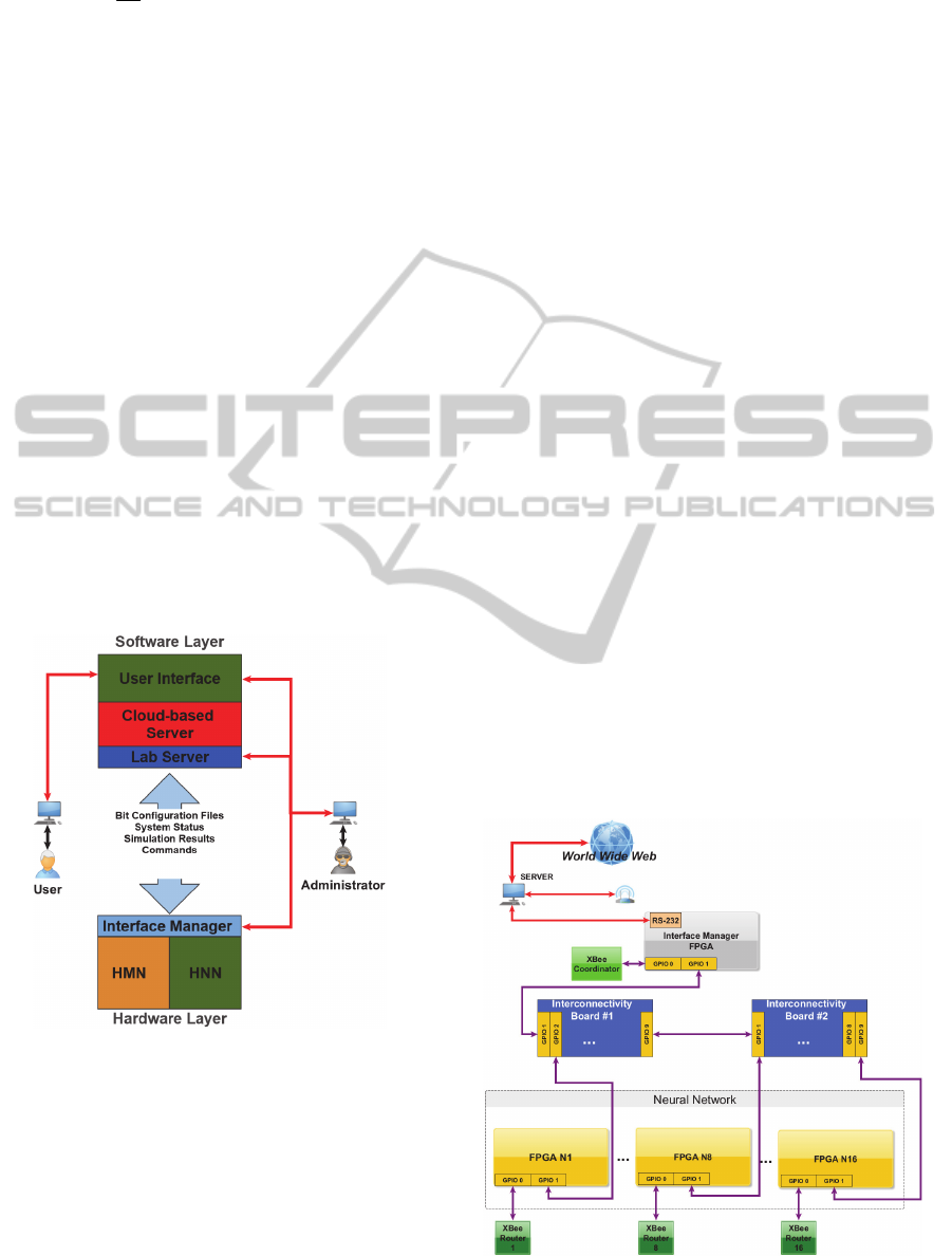
The project aims to develop a powerful
framework capable of performing realistic
simulations of the C. elegans nervous system. An
overview of the full Si elegans framework
architecture is depicted in Figure 1.
Figure 1: Si elegans framework architecture.
Users are assumed to include neuroscientists,
biologists, computational intelligence and intelligent
systems researchers interested in studying the C.
elegans’ BNS.
It is anticipated that users connect to Si elegans
platform via a Web Portal using a variety of
computational devices. Users can activate Si elegans
using the User Interface (UI). The UI provides an
advanced graphical Hardware Neuron Network
(HNN) and Hardware Muscle Network (HMN)
definition environment where users can define
simulations using predefined neural
models/parameters or create their own and then run
their simulation on the dedicated hardware.
The UI will also provide a dynamic environment
(Virtual Arena) both for emulating the worm’s
physical sensory input interactions with the world,
and for observing the resulting behaviour of the
nematode in a 3D cinematic virtual environment.
The main aim of the work presented in this paper
is related to the development of the hardware layer,
which is composed of 330 tightly coupled FPGA
boards, arranged in a set of conventional racks.
These correspond to the C.elegans 302 neurons and
95 muscles. The focus of the paper is an exploration
of non-wired connectivity schemes, in this case a
wireless network based synaptic connectivity
scheme.
5 SMALL SCALE Si elegans HNN
In this section a small scale prototype system
composed of 16 neuron FPGAs and one Interface
Manager (IM) FPGA is implemented for concept
validation. All FPGAs are Terasic Altera-based DE4
boards.
An XBee module was installed on each of the17
FPGA boards via custom built XBee shields
connected to one of the two 40-pin general purpose
inputs outputs (GPIO). The second 40-pin GPIO was
used to interconnect the 17 FPGAs using a
Figure 2: 16 HNN architecture.
Sielegans-ComputationalModellingofC.elegansNematodeNervousSystemusingFPGAs
171

specifically designed interconnect board to provide
wired synaptic connections. These latter wired
connections allow for a comparison between the two
connection schemes and are not used during XBee
simulations.
The Interface Manager (IM) is connected to a
Server through an RS-232 cable that is used to
receive simulation parameters from the Server and to
send the simulation results back to the Server. Figure
2 represents the 16 HNN architecture.
5.1 Hardware Layer
The hardware layer of the small scale 16 HNN is
composed of:
Interface Manager (IM): this programs the
neuron FPGAs and ensures that all the neurons
are on the same biological clock cycle. Collates
the simulation results and sends back to the
Server.
Server: sends simulation parameters, receives
and visualizes simulation results;
Hardware Neural Network (HNN): performs
computations;
XBee modules: transmits/receives spikes
across the Zigbee mesh network (ZMN).
Interconnectivity Board: wired intercom-
nectivity of neurons and interface manager for
comparison with the wireless connectivity
scheme.
5.1.1 Interface Manager
The IM shares 5 channels that are used to exchange
data and for synchronization with the neuron
FPGAs. Each channel is used to transmit/receive the
following data type:
Biological Clock Pulse (BCP): transmits one
pulse per timestamp. These pulses are used to
inform the neurons that a new timestamp has
started;
Transmit data (BTx): broadcasts data from the
IM across all the neurons;
Receive data (BRx): receives neuron
computation ended confirmation from all the
neurons.
Master Clock: 1.8432 MHz;
UART Clock: 115.200 KHz.
The Server sends the simulation parameters to the
IM, and the IM stores the simulation parameters
while broadcasting the parameters through the BTx
channel using the same UART protocol that is used
between the Server and the IM. If at least one spike
was generated during that Biological Clock Cycle
(BCC) then the IM sends those spikes back to the
Server and broadcasts that information through the
ZMN or the wired connections.
The IM Biological Clock controller generates
pulses that are used to ensure that all the neurons are
at the same biological clock cycle even if different
types of neuron models, with different computation
times, are running in different FPGAs.
5.1.2 Server
The Server is used to generate and send simulation
parameters as well as receive and visualize the
simulation results. It is connected to the IM through
the COM port (RS-232). The COM port is
configured with a baudrate of 115.2 kHz, 1 stop bit,
8 bits and no parity.
5.1.3 HNN
The HNN is composed of 16 neuron FPGAs. Each
neuron FPGA has two neuron models that were
described in VHDL. The IM broadcasts the
configuration parameters sent by the Server to all
neuron FPGAs.
During the simulation period the neuron FPGAs
receive BCPs. When a new BCP is received the
neuron controller provides the buffered synaptic
inputs states to the neuron model and the new
membrane potential is calculated. If the membrane
potential reaches the threshold then a spike is
generated and sent to the neuron controller. The
neuron controller sends the neuron ID and the spike
through the ZMN to the IM and if the computation is
finished the neuron sends a neuron computation
ended confirmation through the BRx using a SPI
protocol.
When the simulation finishes the IM sends the
simulation data for that BCP and stops the
simulation.
5.1.4 Zigbee Mesh Network (ZMN)
Each XBee module was configured using the Digi
X-CTU software. The XBee modules used on the
neuron FPGAs were programmed as Routers and the
XBee module used on the IM was configured as
coordinator. Each router was programmed to
send/receive data to/from the coordinator XBee (see
Figure 3).
NEUROTECHNIX2014-InternationalCongressonNeurotechnology,ElectronicsandInformatics
172
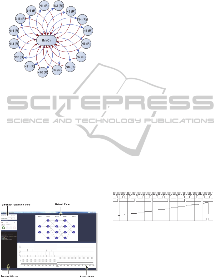
Figure 3: Zigbee mesh topology.
5.2 Software Layer
A simple software test bed was developed (Si
elegans System Builder) which allows the user to
describe and configure the desired network
configuration to be carried out on the FPGAs. The
software is presented in a simple “wizard” format
which asks the user a series of questions about their
configuration requirements. These requirements
comprise of information about network topology and
the neural models/parameters used throughout the
network. This test bed enabled testing of the
described 16 HNN.
Currently the user can implement a network with
a maximum of 16 neurons chosen from a pre-
defined library of neural models (at present,
Integrate and Fire or Leaky Integrate and Fire).
Furthermore, the user can change any of the
available model parameters and can implement the
desired network interconnection.
Figure 4: Screen shot of the Si elegans System Builder
Wizard.
Once the Si elegans System Builder creates the
necessary files the user can upload the configuration
to the FPGAs and start a simulation via a simulation
tool provided by the Si elegans System Builder
software (see Figure 4).
This tool allows the user to interact with the
hardware in several ways. Firstly, in the Simulation
Parameters Pane the user can specify the time step of
the simulation, the required simulation length, the
COM port used to connect to the hardware and the
file to be uploaded. Below this the Terminal
Window, which informs the user about the upload
success and simulation progress. The Network
Stimulation Pane displays a graphical representation
of the configuration network. Finally, the Results
Pane displays simulation results to the user in real
time. The main aim of this software is to provide the
ISRC with a simple to use, full software test bed for
testing the developed FPGA neural emulation
platform. It is not intended to replace the full virtual
arena being developed by partner Vicomtech.
6 RESULTS
The 16 neuron small scale system consists of two
well-known neural models were developed:
Integrate and Fire (Gerstner and Kistler, 2002)
Leaky Integrate and Fire (Gerstner and Kistler,
2002)
Simulation results of these neural models can be
seen in Figure 5 and Figure 6 where each model has
been tested individually using the Mentor Graphics
Questa Sim 10.1d.
Figure 5: Simulation results of the Integrate and Fire
neuron model on Mentor Graphics Questa Sim 10.1d.
Note: the first row is the biological clock, rows 2 and 3
represent synaptic inputs, row 4 represents the neuron
membrane voltage and row 5 represents the output spikes
of the neuron.
In each test case 2 synaptic input spike trains
with a frequency of 250Hz and 100Hz respectively
were generated to stimulate the neuron.
Furthermore, the following parameters were used:
Cm = 1nF; Rm = 40MΩ; vth = 10mV; vreset =
2mV; vref = 5ms; weight = 1.
Sielegans-ComputationalModellingofC.elegansNematodeNervousSystemusingFPGAs
173

Figure 6: Simulation results of the Leaky Integrate and
Fire model on Mentor Graphics Questa Sim 10.1d. Note:
the first row is the biological clock, rows 2 and 3 represent
synaptic inputs, row 4 is the neuron membrane voltage and
row 5 represents the output spikes of the neuron.
A series of experiments was then performed on
the 16 neuron small scale FPGA hardware using the
feed-forward, partially connected neural network
configuration described in Figure 7, which was
developed in the Si elegans System Builder. These
experiments were first carried out with XBee
wireless synaptic transmission and then with
hardwired synaptic connections, thus allowing a
comparison of both methods. A number of different
network configurations with neurons models/
parameters were examined, to ensure that the system
could handle different models at the same time.
Figure 7: Neural network topology.
When a simulation is started, the configuration
hex stream is uploaded through the COM port to the
interface manager which relays the configuration
setup to the neuron boards. After uploading the
configuration hex streams the Interface Manager
starts the simulation. The simulations ran for 10000
Biological Clock Cycles (BCC) with a time step of
1ms; total simulation time = 10s.
During the simulations a constant current was
applied to neuron 1 for the first 5s and then a
constant current was applied to neuron 2 for the
remainder of the simulation. If a neuron spikes as a
result of stimulation or synaptic activity during a
BCC the information is sent back to the Interface
manager. All spikes during a BCC are collated and
then broadcast by the Interface Manager to all
neurons. Each neuron then listens for spikes that
were emitted by pre synaptic neurons and a new
BCC starts. Furthermore the Interface Manger relays
this spike information back to the Server. Typical
results generated by a simulation can be seen in
Figure 8 and Figure 9.
Figure 8: Typical simulation results 1s – 10s (all IF
neurons).
Figure 8 presents a network comprised only of IF
neurons with each synapse given a weight of 2. Note
that when neuron 1 and 2 are stimulated with a
constant current injection they fire the fastest and
cause all other spiking activity throughout the
network. As expected, as the information propagates
through the network each successive layer’s firing
rate decreases. Furthermore as the stimulus changes
from neuron 1 to neuron 2 the firing patterns
throughout the network also change.
Figure 9: Typical simulation results 4s -10 s (all LIF
neurons).
Figure 9 describes results from a network
comprising of LIF neurons. In this case the weights
were randomly initialised between 4 and 9. It is
again clear that as network stimulation changes the
firing patterns also change. Although these results
have no biophysical meaning, they do enable testing
of the small scale hardware architecture and neural
model functionality.
Results from both wired and wireless connection
schemes were analysed for differences; both
methods provided exactly the same results therefore
no packet loss occurred during wireless simulation.
NEUROTECHNIX2014-InternationalCongressonNeurotechnology,ElectronicsandInformatics
174

However, there was a dramatic increase in
simulation run time during wireless experiments.
Wireless simulations required ~15 times more time
to complete. This was a result of the 100ms delay
necessary between XBee communication
transmissions.
Finally, the 16 neurons HNN was also used to
develop the communications protocol that will be
used in the final system. Furthermore, the use of the
COM port helped the authors to validate the data
payload protocol that is exchanged between devices,
however this type of communication is slower when
compared with an Ethernet connection. In the near
future the COM port will be substituted by an
Ethernet connection which will result in a
communications speed increase.
7 CONCLUSIONS AND FUTURE
WORK
Currently simulation of neural networks comprised
of biophysical realistic models of neurons requires
prohibitively long simulation times. Therefore large
scale simulations generally utilise phenomenological
models which do not capture the rich dynamics of
biophysical models. The Si elegans project is a
multi- platform environment which aims to emulate
faithfully the small yet extremely complex nervous
system of the C. elegans nematode. Furthermore the
platform will be freely accessible to neuroscientists,
enabling them to easily explore the different neural
behaviours and functions of the C. elegans worm.
The hardware framework will also be scalable,
allowing neuroscientists to define new neural
models and connectomes. This will ultimately lead
to a better understanding of how neural systems
function.
In this paper early evaluation work on the
hardware architecture of the Si elegans framework
was described, where both wired and wireless
synaptic connectivity were configured and
compared. The XBee solution resulted in longer run
times when compared to wired connected synapses.
This was due to the extra information broadcast by
the XBee protocol for each spike and the required
delays between transmissions, whereas the wired
connection protocol only has to send a single bit for
each spike. Therefore, a wireless synaptic
transmission of spikes must be reduced to a single
bit to achieve the fastest possible simulation times.
This will be achieved via optical based synaptic
interconnect boards currently under development by
our partners in Istituto Italiano di Technologia (IIT).
The next stage of this work will be to integrate
the optical based synaptic interconnect boards.
During this stage all wired connectivity will be
removed and the system will be retested by re-
running all simulations previously carried out. This
will ensure that developed system is capable of
driving and communicating correctly with the new
synaptic interconnect boards. The RS-232
transmission protocol which allows communication
with the Server will also be changed to Ethernet
which will increase information throughput and
decrease simulation run times.
Work is also currently underway to increase the
neuronal model library to include more detailed
neural models such as Hodgkin and Huxely, as well
as including synaptic models and STDP learing.
Finally, the small scale system will be developed
to full scale with custom made FPGA boards and
integrated into the complete Si elegans system with
other system components developed by our project
partners National University Ireland Galway
(NUIG), IIT and Vicomtech. NUIG are currently
focussed on implementing a module which allows
users to define new neural models using various
neural modelling languages which are then
automatically translated to HDL for use with the Si
elegans hardware. The software layer UI and virtual
arena which grants the user access to the framework
and provides simulation analysis tools to the user is
currently uder development by Vicomtech.
ACKNOWLEDGEMENTS
The research leading to these results has been
partially supported by the Si elegans project, which
has received funding from the European
Community’s 7th Framework Programme under the
Neuro BioInspired Systems Project Grant agreement
601215. We also wish to thank Altera University
Program for FPGA board donations.
REFERENCES
Abdul Ghayum, M. S. (2010). Thesis on Comparative
study of wireless protocols : wi-fi, bluetooth, ZigBee,
WirelessHART and ISA SP100, and their effectiveness
in industrial automation. Texas: The University of
Texas at Austin.
Ang, C., McEwan, A., van Schaik, A., Jin, C., and Leong,
P. (2012). FPGA implementation of biologically-
Sielegans-ComputationalModellingofC.elegansNematodeNervousSystemusingFPGAs
175

inspired auto-associative memory. Electronics Letters,
48(3), 148 - 149 .
FitzHugh, R. (1961). Impulses and physiological states in
theoretical models of nerve membrane. Biophysical
Journal, Volume 1(6);, 445-466.
Gerstner, W., and Kistler, W. M. (2002). Spiking Neuron
Models . Cambridge: Cambridge University Press.
Glackin, B., McGinnity, T. M., Maguire, L. P., Wu, Q. X.,
and Belatreche, A. (2005). A Novel Approach for the
Implementation of Large Scale Spiking Neural
Networks on FPGA Hardware. Computational
Intelligence and Bioinspired Systems, 3512, 552-563.
Hodgkin, A. L., and Huxley, A. F. (1952). A quantitative
description of membrane current and its application to
conduction and excitation in nerve. The Journal of
Physiology Volume 117(4);, 500–544.
Iakymchuk, T., Rosado, A., Frances, J., and Batallre, M.
(2012). Fast spiking neural network architecture for
low-cost FPGA devices. 7th International Workshop
on Reconfigurable Communication-centric Systems-
on-Chip (ReCoSoC), 1 - 6 .
Izhikevich, E. (2003). Simple model of spiking neurons.
Neural Networks, IEEE Transactions on, Volume: 14 ,
Issue: 6, 1569 - 1572.
Kaur, H., and Sharma, S. (2013). A Comparative Study of
Wireless Technologies: Zigbee, Bluetooth LE,
Enocean, Wavenis, Insteon and UWB. International
Conference On Recent Trends In Computing And
Communication Engineering - RTCCE 2013 (pp. 273 -
276). Hamirpur, Himachal Pradesh, India :
International Conference On Recent Trends In
Computing And Communication Engineering -
RTCCE 2013.
Lee, J.-S., Su, Y.-W., and Shen, C.-C. (2007). A
Comparative Study of Wireless Protocols: Bluetooth,
UWB, ZigBee, and Wi-Fi. Industrial Electronics
Society, 2007. IECON 2007. 33rd Annual Conference
of the IEEE (pp. 46 - 51 ). Taiwan: IEEE.
Misra, J., and Saha, I. (2010). Artificial neural networks in
hardware: A survey of two decades of progress.
Neurocomputing(74), 239 - 255.
Mohamad, K., Mahmud, M., Adnan, F., and Abdullah, W.
(2012). Design of single neuron on FPGA. 2012 IEEE
Symposium on Humanities, Science and Engineering
Research (SHUSER), 133 - 136 .
Morris, C., and Lecar, H. (1981). Voltage oscillations in
the barnacle giant muscle fiber. Biophysical Journal,
Volume 35(1), 193–213.
Nagumo, J., Arimoto, S., and Yoshizawa, S. (1962). An
Active Pulse Transmission Line Simulating Nerve
Axon. Proceedings of the IRE, Volume: 50 , Issue: 10,
2061 - 2070 .
Pande, S., Morgan, F., Seamus Cawley, T. B., Smit, G.,
McGinley, B., Carrillo, S., McDaid, L. (2013).
Modular Neural Tile Architecture for Compact
Embedded Hardware Spiking Neural Network. Neural
Processing Letters, Volume 38, Issue 2, 131-153.
Salapura, V., Gschwind, M., and Maischberger, O. (1994).
A fast FPGA implementation of a general purpose
neuron. Em R. W. Hartenstein, and M. Z. Servít,
Field-Programmable Logic Architectures, Synthesis
and Applications
(pp. 175-182). Prague, Czech
Republic: Springer Berlin Heidelberg.
Seth, S., Gankotiya, A., and Jindal, A. (2010). A
Comparative Study between Wireless Local Area
Networks and Wireless Mesh Networks. Computer
Engineering and Applications (ICCEA), 2010 Second
International Conference on (pp. 192 - 196 ). Bali
Island: IEEE.
NEUROTECHNIX2014-InternationalCongressonNeurotechnology,ElectronicsandInformatics
176
