
Neuron Models in FPGA Hardware
A Route from High Level Descriptions to Hardware Implementations
Finn Krewer, Aedan Coffey, Frank Callaly and Fearghal Morgan
College of Engineering and Informatics, National University of Ireland, Galway, Ireland
Keywords:
Brain-Inspired Computation, Nervous System Emulation, Biological Neural Networks, Spiking Neural
Networks, Field-Programmable Gate Arrays, NeuroML and Low Entropy Model Specification.
Abstract:
This paper presents the LEMS2HDL toolsuite which converts Low Entropy Model Specification
(LEMS) neuron/neural network models to synthesisable Hardware Description Language (HDL) hardware
descriptions. The LEMS2HDL process will provide a route for the neuroscience community to perform
accelerated Field-Programmable Gate Array (FPGA) hardware implementations of the growing library of
LEMS neuron/neural network models. The paper describes the LEMS to HDL conversion process and
references the previously reported vicilogic platform. The paper compares the resulting FPGA hardware
simulation of three LEMS neuron models with the LEMS model simulation.
1 INTRODUCTION
Computational neuroscience includes the study of
brain functions using simulations of networks of
neuron models. Consequently, it has become
increasingly important to simulate large numbers of
often very complex neuron models (Maguire et al.,
2007). High levels of biological realism are desired
in neuron and synapse model simulations to help
improve our understanding of various brain functions.
Hardware acceleration can offer improvements in
simulation speeds of large neural networks. A number
of hardware platforms are being developed in order to
accelerate the simulation of large or complex neural
networks. These include the Spinnaker (Furber et al.,
2013) and Bluehive (Moore et al., 2012) projects.
Field Programmable Gate Array (FPGA)
reconfigurable hardware devices provide vast
concurrent hardware logic resources on which neural
networks can be implemented (Pande, 2014; Maguire
et al., 2007). Current FPGAs contain up to 2 million
logic cells (Xilinx, 2014). FPGAs are reconfigurable
and enable the implementation of high performance
parallel designs. The process to digital logic hardware
implementation typically captures the design using
synthesisable hardware description language (HDL)
(such as Very High Speed Integrated Circuit (VHSIC)
Hardware Description Language (VHDL) or Verilog).
FPGA technology implementation follows synthesis
of the HDL, and a mapping and routing of the design
using FPGA hardware logic resources.
The general neuroscience community is often
not familiar with digital logic design and hardware
implementation processes, hardware description
language (HDL) modelling, or the related Electronic
Design Automation (EDA) tools. The authors have
developed LEMS2HDL as part of the Si elegans
research project in order to contribute to the provision
of an automated and accessible route from high
level neuron model description to FPGA hardware
implementation, hardware execution and model
behaviour readback and analysis.
The Si elegans research project which aims to
develop a Hardware Neural Network (HNN) and
virtual environment to simulate the nervous system
of the Caenorhabditis elegans (C. elegans) nematode.
The HNN will consist of 302 FPGAs each configured
with one complex neuron model. This openly
accessible system will be integrated into a web
platform to allow researchers to develop very detailed
models of the nervous system of the C. elegans.
Extensive libraries of neuron models
have been created using languages such as
the NEURON (Carnevale and Hines, 2006),
BRIAN (Goodman and Brette, 2008) and
GENESIS (Bower et al., 1998) scripting languages.
Large hardware accelerated neural network platforms
such as Spinnaker and Bluehive aim to support
standard high level descriptions of neuron models
in order to make these platforms more accessible to
177
Krewer F., Coffey A., Callaly F. and Morgan F..
Neuron Models in FPGA Hardware - A Route from High Level Descriptions to Hardware Implementations.
DOI: 10.5220/0005190501770183
In Proceedings of the 2nd International Congress on Neurotechnology, Electronics and Informatics (-2014), pages 177-183
ISBN:
Copyright
c
2014 SCITEPRESS (Science and Technology Publications, Lda.)

neuroscientists.
The Low Entropy Model Specification
(LEMS) (Gleeson et al., 2011) is a language
used to describe neuron models and neural networks
functionally. LEMS is a declarative language which is
amenable to use by persons not trained in electronic
engineering, computer science or information
technology. A large library of complex and diverse
LEMS neuron models exists and forms the basis of
the NeuroML 2 neural network description language.
LEMS descriptions are often exported to various
software simulators for optimised execution with the
NEURON and BRIAN simulators already supported.
VHDL is also a declarative language which is
commonly used to describe synthesisable digital
logic. It is possible to manually describe any
time step simulated neuron model using VHDL.
However, the hardware design process, VHDL
capture and typical tool flow is arguably more difficult
than the development of software neuron models
or the mathematical descriptions underlying neural
computations through LEMS. The provision of an
appropriate high level neuron modelling language
and automated generation of synthesisable HDL and
automated FPGA implementation and interaction can
offer a viable route for neuroscientists to achieve
hardware neuron simulations.
The LEMS2HDL toolsuite automatically converts
flexible high level LEMS functional descriptions
of neuron models to synthesizable VHDL designs.
The paper presents simulation results of three
LEMS models and the LEMS2HDL generated VHDL
models. Results demonstrate agreement between
LEMS and VHDL simulations within the limits of
fixed point logic.
The three LEMS models chosen for conversion
are the iafTauCell, the iafTauRefCell and
the iafRefCell with two synapses of type
expOneSynapse. These models were chosen as
they are standard NeuroML2 models and express
many standard neuron model features. These models
also use a wide range of behavioural descriptions
representing the majority of LEMS algorithms. All
three models are leaky integrate and fire neurons
with both iafTauCell and iafTauRefCell returning to
their leak reversal potential with a time course tau.
In addition to this decay the iafTauRefCell describes
a refractory period after a spike where membrane
potential integration is halted. In this paper the
iafTauCell and the iafTauRefCell are used without
synaptic inputs, instead the leak reversal potential
is set above the threshold potential. The iafRefCell
is a leaky integrate and fire cell with membrane
capacitance, a leakConductance, a leakReversal and
a refractory period. The iafRefCell is converted here
together with two synapses of type expOneSynapse.
The expOneSynapse is an ohmic synapse model
whose conductance rises instantaneously on receiving
a spike event, and which decays exponentially to zero
with time course tau. The example LEMS models
and the LEMS2HDL program are available as part
of the org.neuroml.neuroml2 and org.neuroml.export
libraries at https://github.com/NeuroML/.
The vicilogic (Morgan et al., 2014) user design
wrapper automates the integration of the LEMS2HDL
exported HDL neuron model with the vicilogic core
hardware and FPGA device pinout, and creates the
FPGA configuration bitstream file. vicilogic provides
a local and remote FPGA configuration, ethernet-
based neuron model parameter configuration and
signal readback. Additionally, a UI Console toolsuite
enables real-time monitoring and visualisation of
internal neuron behaviour.
The structure of the remainder of the paper is
as follows: Section 2 outlines the LEMS2HDL
conversion process and VHDL fixed point modelling
considerations. Section 3 compares the simulation
accuracy of three example LEMS software and FPGA
hardware models, and presents FPGA resource usage
for each model. Section 4 concludes the paper and
highlights future work.
2 METHODS
This section outlines the LEMS to HDL conversion
process and the LEMS features currently supported
by the LEMS2HDL application. Considerations for
the support of synthesisable fixed point logic and
neural computation model time derivative solvers in
VHDL are also described.
2.1 LEMS to VHDL Conversion
The LEMS2HDL conversion process aims to
map all features of the LEMS language to
synthesisable VHDL descriptions. Many LEMS
features are converted directly through the use
of VHDL templates described in the Apache
Velocity (Foundation, 2007) templating language.
While LEMS is used to specify neurons, synapses,
connections and simulation parameters, the
LEMS2HDL process converts only the LEMS neuron
and synapse models to VHDL. The vicilogic server
and FPGA IP core provide hardware simulation
control, neuron synaptic input stimulus application
and readback of all neuron model internal signals.
NEUROTECHNIX2014-InternationalCongressonNeurotechnology,ElectronicsandInformatics
178

The input to the conversion process consists of
a LEMS neuron and optionally multiple synapse
models. A LEMS neuron model can comprise a
number of nested “components”. Firstly, a VHDL
entity description is generated from the component
ports. Each component exposes a number of
variables (LEMS “exposures”) and expects a number
of “parameters”, such as threshold voltage or leakage
current which are specified to be of certain SI units.
These parameters and exposed variables are converted
into fixed point numbers of varying precision and
ranges as detailed in Section 2.2. In addition each
component can send and receive spike events to/from
other components (on LEMS “event ports”). Each
event port is marked as an in or out port and is mapped
to single bit signals in the VHDL entity descriptions.
Each LEMS component contains “state variables”
which collectively describe the state of a model
or component. State variables are described as
fixed point numbers similar to parameters and
exposures. LEMS “dynamics” update state variables
in the component based on events from event ports
(LEMS “on event”), on the passage of time (LEMS
“time derivative”) or on other variable changes
(LEMS “on condition”). A form of state machine
(LEMS “regimes”) can be used in LEMS to apply
different dynamics such as a refractory period and an
integration regime at different times in a component.
This is directly translated to the commonly used
Finite State Machine (FSM) construct in VHDL.
Due to the interplay of all dynamics on a single
state variable it is necessary to integrate all relevant
dynamics within a single VHDL process which drives
said state variable. The same is true for regimes and
outward event ports. As such the exporter creates a
single VHDL process for each state variable, output
event port and one for a set of regimes. This process
integrates, using fixed point logic, the effects of the
“on condition”, “on event” and “time derivative”
LEMS structures on a state variable, output event
port or regime. Code listing 1 illustrates a LEMS
sample component while code listing 2 illustrates the
automatically exported VHDL of the state variable v
driver process.
2.2 Fixed Point Logic and Time
Derivative Implementation
Fixed point logic generally has a smaller footprint
than floating point logic in hardware (Be
ˇ
cv
´
a
ˇ
r and
ˇ
Stukjunger, 2005), and a known precision. However
fixed point logic suffers from a limited dynamic
range compared to floating point logic. In order
to efficiently implement neuron models in hardware,
it is common to use fixed point logic to perform
calculations of neuron dynamics and state.
In LEMS, standard dimensions are defined to
restrict developers to creating neuron and synapse
models with variables and dynamics that are
dimensionally consistent. Each dynamic in a LEMS
model is verified to be dimensionally consistent
by the reference LEMS interpreter (available at
https://github.com/LEMS/jLEMS/). To minimize
FPGA hardware usage the LEMS2HDL process
assigns a fixed point integer and fractional bit length
for each LEMS model variable. Therefore, voltage
and current are not described by the same number
of bits, rather an optimum bit length is choosen for
each dimension. The bit length for each variable
type is chosen empirically based on the smallest and
largest possible absolute values of a signal during a
simulation. This ensures that the minimum possible
number of bits are choosen to represent a variable.
Listing 1: LEMS code describing the iafTauCell, this
component is part of the NeuroML2 Core Types library
of standard neuron models. This can be found at
https://github.com/NeuroML/NeuroML2.
< ComponentType name =" iafTauCell "
exte n d s = " baseI a f " de s c r i p t i o n ="
Integr a t e and fire cell wh i ch
retu r n s to its lea k re v e r s al
potent i a l of _ l e a k R e v e r s a l wit h a
ti me cours e _t au " >
< Param e t e r na me = " l e a k R e v e r s a l "
dimens i o n =" volta g e "/ >
< Param e t e r na me = " tau " d i mension =
" time " / >
< D y n a m i cs >
< StateVariable name ="v"
expos u r e = " v "
dimens i o n =" volta g e "/
>
< TimeDeri v a t i v e varia b l e = " v "
val ue = " ( leakReversal
- v) / tau " / >
< O n S t art >
< StateA s s i g n m e n t
varia b l e = " v " valu e = "
res et " / >
</ OnSt a r t >
< OnCondition t est = " v . gt .
thr e s h " >
< StateA s s i g n m e n t
varia b l e = " v " valu e = "
res et " / >
< E v e n t O ut port = " spik e " / >
</ OnCondition >
</ Dynami c s >
</ Co m p o n e n t T y p e >
NeuronModelsinFPGAHardware-ARoutefromHighLevelDescriptionstoHardwareImplementations
179

Software and digital hardware simulations of
biological neurons are commonly time step driven. At
every discrete time step the state of neuron models
such as the membrane potential is updated. Time
derivatives in LEMS are used to model state variables
changes at every discrete time step. Time derivatives
describe the Ordinary Differential Equations (ODE)
acting on state variables. Forward Euler integration
is a first order integration method which provides
an efficient hardware implementation (Maguire et al.,
2007) to solve ODEs in the generated VHDL models.
Listing 2 illustrates a VHDL model of the iafTauCell
LEMS model (listing 1) using the forward Euler
method to calculate the state variable v. The
variable sv voltage v temp 1 is the next value of
the state variable v based on the time derivative
alone. Using more accurate numerical integration
schemes for ODEs such as Runge-Kutta fourth-
order approximation would result in larger hardware
resource usage.
Listing 2: VHDL code describing the combinational
process responsible for calculating the next value of the
state variable v.
sv_p r o c e s s _ c o m b_0 :process
variable s v _ v o l t age_ v _ t e m p _ 1 :
sfi x e d (2 downto -24) ;
variable s v _ v o l t age_ v _ t e m p _ 2 :
sfi x e d (2 downto -24) ;
begin
sv_v o l t a g e _ v_tem p _ 1 := resiz e (
sv_vol t a g e _ v _ i n + ( (
p_v o l t a g e _lea k R e v e r sal -
sv_vol t a g e _ v _ i n ) *
p_ti m e _ i n v _ t a u_in v ) *
p_ti m e _ t imeste p ,2 , -24) ;
if T o_slv ( r e size (
sv_vol t a g e _ v _ i n - (
p_vol t a g e _ t h r e s h ) ,2 , -18) )
(2 0) = ’0 ’ then
sv_v o l t a g e _ v_tem p _ 2 :=
res i z e ( p _ v o l tage_res e t
,2 , -24) ;
else
sv_v o l t a g e _ v_tem p _ 2 :=
sv_ v o l t a g e _ v_tem p _ 1 ;
end if;
if reset_model = ’1 ’ then
sv_v o l t a g e _ v _ n ext <= re s i ze
( p _ v o l t a g e _ r e s e t , 2
, -24 ) ;
else
sv_v o l t a g e _ v _ n ext <=
sv_ v o l t a g e _ v_tem p _ 2 ;
end if;
end process;
3 RESULTS
This section compares the simulation accuracy of
neuron models in LEMS and FPGA hardware, and
presents Xilinx XC6SLX16 FPGA resource usage for
each model.
Prior to conversion to VHDL each LEMS model
is simulated for 100 ms (10,000 steps of 0.01 ms). For
all simulations, input spike stimulus, neuron variable
exposures and neuron output spikes are recorded.
Identical parameter configuration is applied to LEMS
and VHDL models. The converted VHDL neuron
model is simulated using the Xilinx ISE Simulator
(ISIM) using identical stimulus and the outputs are
once again recorded. In the next step the VHDL
design is inserted into the vicilab testbed system for
synthesis and FPGA configuration and simulation.
The same stimulus is applied to the FPGA model
and all outputs are recorded using the vicilab ethernet
interface. The paper presents only LEMS and FPGA
simulation results, ISIM simulation results were used
solely for design purposes and VHDL verification.
Table 1 illustrates the average absolute difference
between the FPGA simulated neuron potential and
its LEMS equivalent for the three neuron models.
Table 1 also presents FPGA slice and Digital Signal
Processing (DSP) utilisation (excluding slices used
for vicilogic FPGA core component).
Figure 1 compares the membrane potential (a)
and conductivity traces (b and c) for the iafRefCell
neuron model with two synapses for the LEMS and
FPGA simulation. The iafRefCell model expresses
a leak current and an absolute refractory period.
The synapse model is the NeuroML2 core type
expOneSynapse model which immediately rises to
a base conductance and decays exponentially to
zero. The iafRefCell model does not express a
hyperpolarization during its refractory period and the
spike threshold is set at -55 mV. During the simulation
in figure 1 synapse 1 is stimulated with a spike train of
period 12 ms and synapse 2 is stimulated with a spike
train of period 13 ms which leads to the iafRefCell
model spiking when two input spikes arrive close in
time. The purpose of this simulation is to demonstrate
the consistency of the FPGA simulation compared to
the reference LEMS implementation.
The deviation between LEMS and FPGA
hardware simulated membrane potential is very
low, and results from using fixed point logic in the
hardware implementation. The deviations are most
pronounced when the current from a synapse is
very small and the neuron has exited its refractory
period. This may lead to spike times that are
not strictly the same as those of more accurate
NEUROTECHNIX2014-InternationalCongressonNeurotechnology,ElectronicsandInformatics
180
Table 1: Average absolute difference between the FPGA simulated neuron potential and its LEMS equivalent for the three
neuron models. FPGA slice and DSP utilisation (excluding slices used for vicilogic FPGA core component). LEMS models
are described in the reference library at https://github.com/NeuroML/NeuroML2.
Neuron and Synapse Model Average Error Slice Utilisation Count DSP Utilisation Count
iafTauCell 0.81mV 75 8
iafTauRefCell 0.78mV 101 8
iafRefCell and 2 expOneSynapse 0.12mV 476 31
floating point simulations. However, numerical
innacuracies cannot be completely excluded with
a finite range of representation, even with floating
point numbers a limited dynamic range can lead to
a loss of information. Another source of error is the
integration scheme itself as discussed in Section 2.2.
The hardware resource utilisation described here
refers to the number of Spartan-6 FPGA slices used
which contain four Look Up Tables (LUTs) and
eight flip-flops each (Xilinx, 2011) and the number
of DSP48A1 slices used which contain an 18 x 18
multiplier, an adder, and an accumulator each (Xilinx,
2011). Table 1 illustrates the requirement of an
additional 26 slices for the iafTauRefCell models
implementation compared to the iafTauCell model
implementation due to the addition of refractory
period support. The use of the iafRefCell (which has
similar functionality to the iafTauRefCell) together
with two synapses requires 23 additional DSP slices.
This indicates that synapse conductance and current
calculations require the most logic. When using more
synapses this logic utilisation will grow considerably
as all synapse contributions must be summed together.
Resource reduction may be obtained in future
iterations of the LEMS2HDL application by time
multiplexing synapse models.
The VHDL neuron models produced by the
LEMS2HDL application have not been compared
to manually designed HDL neuron models. It is
expeted that if a hand written model were to use
the same accuracy of fixed point logic then it would
require similar logic resources on a FPGA. Some
inefficient logic utilisation by the converter may be
identified by a HDL designer and corrected. For
example, an unused regime may be removed by
hand but would currently not be identified by the
LEMS2HDL application. It is expected that over time
the LEMS2HDL application will mature to find such
cases and convert LEMS to VHDL more efficiently.
4 DISCUSSION
The automated conversion of high level neuron model
descriptions to FPGA hardware implementations can
potentially enable researchers to accelerate the testing
of new and novel neuron models in hardware, while
also enabling faster simulations of existing neuron
models.
Simulation results of standard neuron models
demonstrate agreement between LEMS simulated
model and converted hardware model behaviour
within the limits of fixed point logic. In
addition FPGA resource usage is reasonably low
indicating that conversion and synthesis of much
larger and more complex neuron models is feasible.
Future models will include Hodgkin–Huxley type
models and multi-compartmental conductance-based
models (W. Gerstner, 2002). This work demonstrates
the viability of the LEMS2VHDL and vicilogic
platform in supporting the general neuroscience
community in practical hardware neuron and neural
network implementation and testing, using FPGA
hardware.
In the current FPGA testbed implementation one
neuron model occupies one FPGA. While this allows
for faster than real time simulations, this also results
in very large FPGA requirements even for small
networks of neurons. An alternative solution using
virtual neurons or time-division multiplexing is more
desireable for the simulation of large neural networks.
By time multiplexing the evaluation pipeline for
a neuron model and switching in and out state
data for different virtual neurons it is possible to
simulate more neurons efficiently using just one
hardware implementation of a neuron. The approach
of time-division multiplexing has been adopted by
hardware platforms such as Spinnaker using ARM
processors (Furber et al., 2013) and has been reviewed
extensively by Glackin et. al(Glackin et al., 2005).
Lastly, many challenge remain to fully supporting
the entire LEMS feature set in VHDL designs. These
include the development of efficient exponential
and natural logarithm calculators required by many
neuron models. Fixed point logic restrictions will
also continue to be a challenge to achieving highly
accurate numeric simulations in hardware.
ACKNOWLEDGEMENTS
This work has been completed as part of the Si-
NeuronModelsinFPGAHardware-ARoutefromHighLevelDescriptionstoHardwareImplementations
181
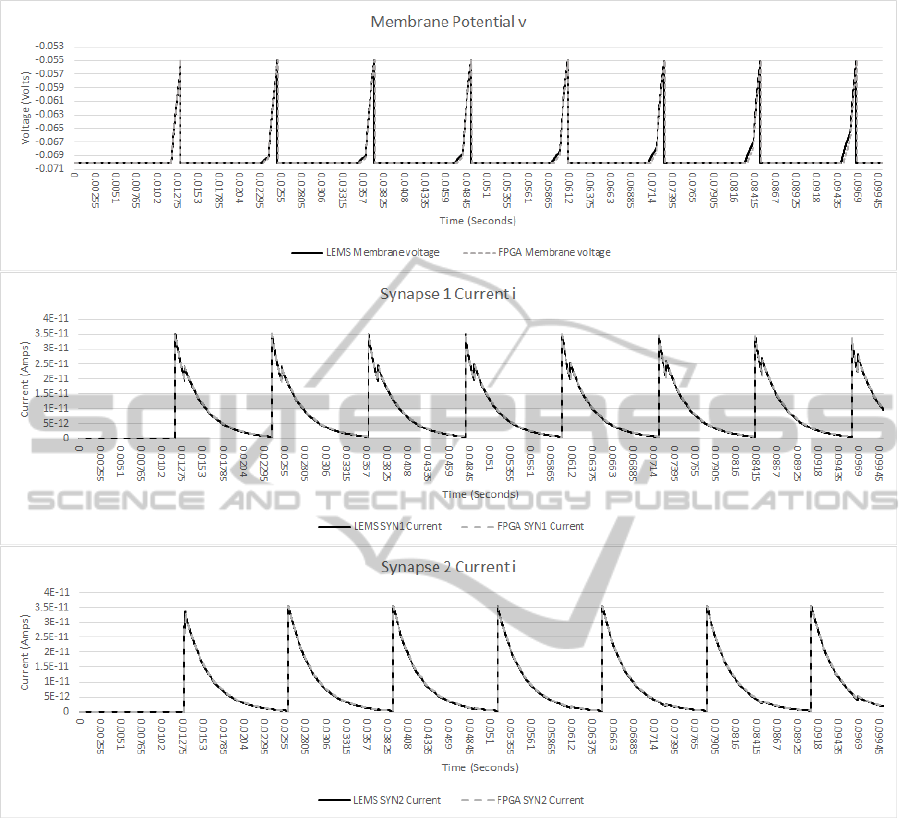
Figure 1: Comparison of membrane potential (a) and conductivity traces (b and c) for the of iafRefCell neuron model with
two synapses for the LEMS and FPGA simulation.
Elegans project funded under FP7 FET initiative
NBIS (ICT-2011.9.11). This work is also supported
by the Irish Research Council under the EMBARK
funding scheme.
REFERENCES
Be
ˇ
cv
´
a
ˇ
r, M. and
ˇ
Stukjunger, P. (2005). Fixed-point
arithmetic in FPGA. Acta Polytechnica, 45(2).
Bower, J. M., Beeman, D., and Wylde, A. M. (1998). The
book of GENESIS: exploring realistic neural models
with the GEneral NEural SImulation System. Telos
Santa Clara, Calif.
Carnevale, N. and Hines, M. (2006). The NEURON Book.
Cambridge, UK: Cambridge University Press.
Foundation, A. (2007). Apache velocity - velocity user
guide.
Furber, S., Lester, D., Plana, L., Garside, J., Painkras, E.,
Temple, S., and Brown, A. (2013). Overview of the
SpiNNaker system architecture. IEEE Transactions
on Computers, 62(12):2454–2467.
Glackin, B., McGinnity, T. M., Maguire, L. P., Wu, Q. X.,
and Belatreche, A. (2005). A novel approach for the
implementation of large scale spiking neural networks
on FPGA hardware. In Cabestany, J., Prieto, A., and
Sandoval, F., editors, Computational Intelligence and
Bioinspired Systems, number 3512 in Lecture Notes
in Computer Science, pages 552–563. Springer Berlin
Heidelberg.
Gleeson, P., Crook, S., Silver, A., and Cannon, R. (2011).
Development of NeuroML version 2.0: greater
extensibility, support for abstract neuronal models and
NEUROTECHNIX2014-InternationalCongressonNeurotechnology,ElectronicsandInformatics
182

interaction with systems biology languages. BMC
Neuroscience, 12(Suppl 1):P29.
Goodman, D. and Brette, R. (2008). Brian: a simulator
for spiking neural networks in python. Front
Neuroinform, 2:5.
Maguire, L. P., McGinnity, T. M., Glackin, B., Ghani, A.,
Belatreche, A., and Harkin, J. (2007). Challenges
for large-scale implementations of spiking neural
networks on FPGAs. Neurocomputing, 71(1–3):13–
29.
Moore, S. W., Fox, P. J., Marsh, S. J., Markettos, A. T., and
Mujumdar, A. (2012). Bluehive - a field-programable
custom computing machine for extreme-scale real-
time neural network simulation. pages 133–140.
IEEE.
Morgan, F., Cawley, S., Coffey, A., Callaly, F., Donovan,
L., Neelen, M., Lyons, D., Nugent, D., Killoran,
P., and O’Loughlin, D. (2014). Vicilogic: Online
learning and prototyping platform for digital logic and
computer architecture.
Pande, S. (2014). Design Exploration of EMBRACE
Hardware Spiking Neural Network Architecture and
Applications. Thesis.
W. Gerstner, W. M. K. (2002). Spiking Neuron Models.
Xilinx (2011). Spartan-6 family overview : Product
specification.
Xilinx (2014). 7 series FPGAs overview : Product
specification.
NeuronModelsinFPGAHardware-ARoutefromHighLevelDescriptionstoHardwareImplementations
183
