
Towards an Electro-optical Emulation of the C. elegans Connectome
Alexey Petrushin, Lorenzo Ferrara, Carlo Liberale and Axel Blau
Dept. of Neuroscience and Brain Technologies (NBT) and Nanostructures Unit (NAST),
Fondazione Istituto Italiano di Tecnologia (IIT), 16163 Genoa, Italy
Keywords: Brain-Inspired Computation, Nervous System Emulation, Connectome, Parallel Information Flow, Digital
Mirror Device (DMD), Microstructured Optical Elements, Structured Illumination.
Abstract: The tiny worm Caenorhabditis elegans features one of the simplest nervous systems in nature. The
hermaphrodite contains exactly 302 neurons and about 8000 connections. The Si elegans project aims at
providing a reverse-engineerable model of this nematode by emulating its nervous system in hardware and
embodying it in a virtual world. The hardware will consist of 302 individual FPGAs, each carrying a
neuron-specific neural response model. The FPGA neurons will be interconnected by an electro-optical
connectome to distribute the signal at the axonal output or gap-junction pin of an FPGA neuron onto the
respective synaptic input or gap-junction pins of those target FPGA neurons that a neuron interconnects
with. This technology will replicate the known connectome of the nematode to allow for an as biologically
meaningful as possible and truly parallel information flow between neurons. This article focuses on the
concepts and first implementation steps of such optical connectome.
1 INTRODUCTION
Caenorhabditis elegans, a soil-dwelling nematode,
is one of the best characterized organisms. The adult
hermaphrodite is comprised of exactly 959 cells,
including 95 body wall muscle cells, 302 neurons
and about 8000 connections, of which about 2000
are electrical junctions. The seemingly low
complexity of this worm has kept researches busy
over the past 50 years without revealing a complete
understanding of its nervous system and the rich
behavioural repertoire emerging from its function.
To fill this void, the Si elegans project aims at the
development of a hardware-based computing
framework that accurately mimics C. elegans in real
time and enables complex and realistic behaviour to
emerge through interaction with a rich, dynamic
simulation of a natural or laboratory environment.
We will replicate the nervous system of C. elegans
on a highly parallel, modular, user-programmable,
reconfigurable and scalable hardware architecture,
virtually embody it for behavioural studies in a
realistic virtual environment and provide the
resulting computational platform through an open-
access web portal to the scientific community for its
peer-validation and use.
2 THE C. elegans CONNECTOME
In C. elegans, the spatial organization of neurons
and their interconnectivity is largely known and
almost fully mapped. The most up-to-date wiring
information covers 279 neurons of the somatic
nervous system, excluding 20 neurons of the
pharyngeal system and three neurons that appear to
be unconnected from the rest (Chen et al., 2006;
Qian et al., 2011; Ruvkun, 1997). Every C. elegans
neuron name consists of either two or three
uppercase letters indicating class and in some cases
a number indicating the neuron number within one
class. If the neurons are radially symmetrical, each
cell has a three-letter name followed by L (left), R
(right), D (dorsal) or V (ventral). A complete list of
C. elegans neurons, their lineage and descriptions
can be found in the ‘individual neuron list’ of the
WormAtlas (Altun, 2014). Neural location and
connectivity maps are available through the
'Neuronal Wiring' section in the WormAtlas
(Wormatlas, 2014). A highly compressed view on
the overall connectivity matrix is given in Figure 1.
Its data is based on work by Dmitry Chklovskii's
group (Chen et al., 2006) that was modified by
Nikhil Bhatla (Bhatla, 2009) for easier processing.
184
Petrushin A., Ferrara L., Liberale C. and Blau A..
Towards an Electro-optical Emulation of the C. elegans Connectome.
DOI: 10.5220/0005190601840188
In Proceedings of the 2nd International Congress on Neurotechnology, Electronics and Informatics (-2014), pages 184-188
ISBN:
Copyright
c
2014 SCITEPRESS (Science and Technology Publications, Lda.)
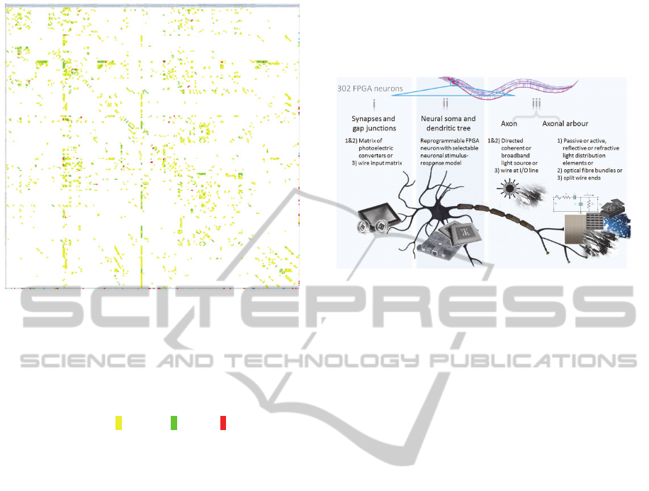
Figure 1: Connectivity matrix of currently 275 neurons
extracted from the Neural Connectivity II dataset by
Varshney et al. (Varshney et al., 2011). Pre-synaptic
neurons listed in the row headers connect to their post-
synaptic target neurons listed in the column headers via
one or up to three simultaneous synaptic connections. Due
to page size limitations, the names of the individual
neurons are not legible. Colour codes for the number of
synaptic connections: 1: yellow, 2: green, 3 red. Electrical
gap junctions and neuromuscular junctions are not
included in this matrix.
3 THE Si elegans CONNECTOME
One of the key challenges and features of the Si
elegans computational platform is the development
and implementation of the 3D electro-optical
interconnectivity concept for the parallel processing
and transmission of neuronal information. In current
2D interconnectivity designs based on static
integrated circuitry-only schemes, network
complexity is limited by 2D interconnectivity
bottlenecks. Thus, inter-neuron connectivity is a
major problem. To circumvent this limitation, other
groups have deployed shared bus-based connectivity
concepts and asynchronous address-based event-
coding/event-representation systems (AES, AER,
NoC, ..) to mimic parallel information transmission.
But they are serial in nature. As long as processing
rates are sufficiently high for a low number of
synaptic connections (several thousands), their serial
nature can be hidden and parallelism be pretended.
However, a system may encounter communication
bottlenecks when a high number of target synapses
need to be addressed simultaneously. In that case,
non-parallelism will become apparent. A more
serious problem of serial-type simulations is their
stochastic jitter in the timing of events that prevent
the accurate and reproducible mimicry of parallel
information flow between neurons.
Figure 2: Concept and elements of an individual Si
elegans FPGA neuron module and its comparison with a
real neuron. Neural activity will arrive at individual input
lines of an FPGA (i) and will be processed by the neuron-
specific stimulus-response algorithm that the FPGA was
programmed with (ii). Its output activity will be
distributed in parallel through signal distribution elements
(iii) to individual input lines (i) of the target FPGA
neurons to which the neuron connects to. In case of signal
propagation by light, incoming activity will arrive as
spatially confined light pulses at individual pixels of
photoelectric converters (synapses/gap junctions) being
individually connected to the individual FPGA input lines.
Neural response activity generated by the neural model
residing on the FPGA will trigger a coherent light source
at one of its output lines (axon). This light will pass
through light distribution elements to distribute activity
onto selected pixels (synapses/gap junctions) of inter-
connected target neurons. In case of electrical signal
transmission through wires, a split-wire bundle will
transmit a digital signal pulse from the axonal output line
of the FPGA to individual synapse/gap junction sockets of
the target neurons. Reproduced with permission from the
Si elegans project consortium.
These limitations will be overcome through
research into free-space communication techno-
logies. This concept picks up on research into free-
space optical computation and build on rapid
progress in optical communication technology, be it
for telecommunication or, more recently, on-chip
and intra-chip optical interconnects (Assefa et al.,
2010; Doany et al., 2012; Loughran, 2010; Orcutt et
al., 2011). The C. elegans connectome will be
replicated by connecting the individual FPGA
neuron modules in a line-of-sight framework
through light. This approach allows for the
distribution of the signal at the axonal output or gap-
junction pin of an FPGA neuron onto the respective
synaptic input or gap-junction pins of those target
TowardsanElectro-opticalEmulationoftheC.elegansConnectome
185
FPGA neurons that a neuron interconnects with. The
involved elements and their biological counterparts
in the Si elegans implementation are depicted in
Figure 2, their respective arrangement in Figure 3.
Because activity in the nervous system is temporally
coded, light intensities will not require amplitude
modulation.
Figure 3: Sketch of one physical arrangement scenario for
FPGA boards and optical line-of-sight interconnection
pathways. An exemplary subset of 9 out of 302 FPGA
boards and their interconnection by structured light beams
is shown. The red arrow depicts the axonal output beam of
a pre-synaptic sending FPGA neuron, which is spatially
patterned by a neuron-specific reflective element at some
distance opposite to the racks and thereby distributed onto
the photoreceptive elements representing synapses or gap
junctions of the post-synaptic target neurons (yellow
arrows). The reflective optical light distribution elements
can either be active (digital mirror device, DMD) or
passive (µ-mirror arrays). 302 of these elements, one for
each neuron, will be strategically arranged in a matrix on
the ‘reflection wall’.
4 OPTICAL LIGHT
DISTRIBUTION ELEMENTS
Neuron-specific reflective microoptical arrays can
be passive or active (Figure 4). They redirect the
portion of an expanded LED or laser beam of fixed
intensity towards different directions in space,
corresponding to the virtual synapses or electrical
junctions (optical receivers connected to the I/O
lines) of the FPGA target neurons that the sending
neuron connects to. Because each neuron connects
to different target neurons or muscles, the
microoptics of the individual neuron-specific arrays
will be all different from each other. Therefore, a
static connectome will require the fabrication of 302
passive micromirrors consisting of a reflective pixel
pattern that projects incoming light to specific
locations on the rack. An active connectome will be
composed of 302 digital mirror devices (DMDs). In
both cases, these reflective arrays will be installed
opposite to the racks carrying the FPGA boards
(Figure 3, right).
Figure 4: Examples of passive and active reflective light
shaping elements (LSEs).
While the connectome of an organism like C.
elegans is thought to not change over its lifetime,
passive reflective devices, once aligned, will result
in a robust interconnectivity matrix. Furthermore, no
electrical power is needed to maintain a projection
pattern. In case new insights on missing connections
are published, individual mirrors with updated
permissive pathways can be fabricated by standard
(electron-beam) photolithography or laser ablation
and replace obsolete mirrors.
A more flexible strategy is the use of active
micromirror devices. They will allow an electronic
re-programming of the connectome. Active
micromirror devices find wide-spread application in
video projectors. While various technologies for
electronically programmable micromirrors exist, the
most ubiquitous is the digital micromirror device
(DMD) pioneered by Texas Instruments. In digital
light processing (DLP) projectors, the image is
created by microscopically small mirrors laid out in
a matrix on a semiconductor chip. Each mirror
represents one pixel in the projected image. The
NEUROTECHNIX2014-InternationalCongressonNeurotechnology,ElectronicsandInformatics
186
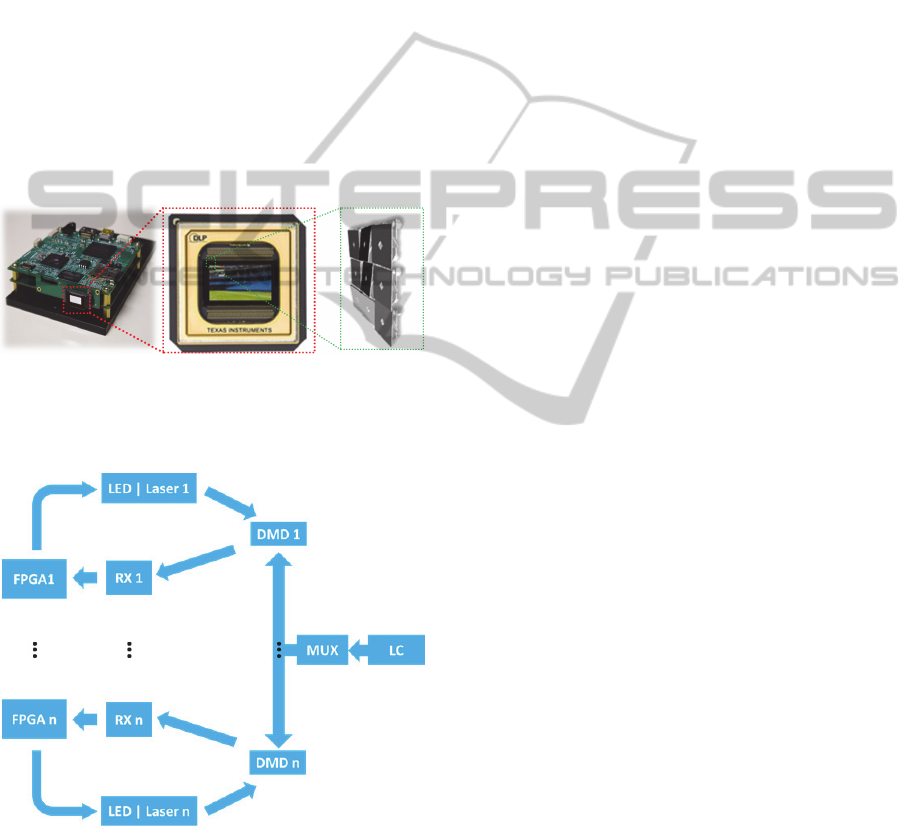
number of mirrors corresponds to the resolution of
the projected image. These mirrors can be
repositioned rapidly between ±12 degrees to reflect
light either through a projection lens or onto a heat
sink (called a light dump). Rapidly toggling the
mirror between these two orientations (essentially on
and off) produces grayscales, controlled by the ratio
of on-time to off-time. If no signal is applied, a
mirror will be held electrostatically in its previous
toggle state through three static memory elements
underneath. This allows the creation of a quasi-static
light distribution pattern that, upon demand, can be
changed anytime on the fly by using a commercial
DMD controller (e.g., DLP® LightCrafter™, Texas
Instruments) (Figure 5). Mirrors can be bundled
(binned) to increase the light intensity at the
projection screen at the cost of decreasing overall
image resolution.
Figure 5: Example of a commercial DMD controller (left,
Texas Instruments), a DMD (middle, Texas Instruments)
and the three-state positioning of micromirrors (+12° light
grey, -12° black, 0° dark grey; right).
Figure 6: A general interconnection scheme based on
multiplexing several (n = 302) DMDs for downloading
individual neuron-specific and quasi-static, but re-
programmable projection patterns (=synaptic/gap junction
connections) onto them through a single DMD controller.
Legend: DMD: digital mirror device; FPGA: field-
programmable gate array; LC: LightCrafter (DMD
controller by Texas Instruments); LED: light-emitting
diode; MUX: multiplexer; RX: (photo) receptive matrix.
A general interconnection scheme is shown in
Figure 6. The main limitation of the LightCrafter
controller is its inability to control more than one
DMD at a time. Considering that DMD mirrors will
remain in the same position if no additional data is
applied to the DMD (although it is suggested to reset
the mirrors no less than 1 Hz to avoid mirror
memory issues), we deploy a multiplexer board
which permits a number of DMDs to share the same
driver board.
5 CONCLUSIONS
Optical interconnection concepts have universal
character and are not restricted to the layout chosen
for the Si elegans platform. Once a convenient
geometry for the emulation of a particular nervous
system or any of its sub-circuits (e.g., a cortical
column) has been identified, neural emitters and
receivers can be arbitrarily allocated in space, and
network-specific optical light structuring and
distribution elements be manufactured to implement
a particular connectome. This approach also allows
for the optical interlinking of several sub-circuits
through dedicated optical ports, e.g., to mimic
cortical layers. In the simplest case, these can be
holes in the support frameworks that are carrying the
neuronal modules of different neural subassemblies.
This free-scaling feature allows for the design of
future generations of highly complex biomimetic
computational architectures.
Ongoing work focuses on the physical
implementation of the control electronics and the
electro-optical components and on the development
of an optimization algorithm for their strategic
relative placement to each other.
ACKNOWLEDGEMENTS
The Si elegans project 601215 is funded by the 7
th
Framework Programme (FP7) of the European
Union under FET Proactive, call ICT-2011.9.11:
Neuro-Bio-Inspired Systems (NBIS).
REFERENCES
Altun, Z. (2014). Individual Neurons. Wormatlas . A
database featuring behavioral and structural anatomy
of Caenorhabditis elegans. from http://www.
wormatlas.org/neurons/Individual%20Neurons/Neuro
nframeset.html
TowardsanElectro-opticalEmulationoftheC.elegansConnectome
187

Assefa, S., Xia, F., and Vlasov, Y. A. (2010). Reinventing
germanium avalanche photodetector for nanophotonic
on-chip optical interconnects. Nature, 464(7285), 80-
84. doi: http://www.nature.com/nature/journal/v464/
n7285/suppinfo/nature08813_S1.html
Bhatla, N. (2009). C. elegans Neural Network: Details.
from http://wormweb.org/details.html
Chen, B. L., Hall, D. H., and Chklovskii, D. B. (2006).
Wiring optimization can relate neuronal structure and
function. Proceedings of the National Academy of
Sciences of the United States of America, 103(12),
4723-4728. doi: 10.1073/pnas.0506806103
Doany, F. E., Lee, B., Rylyakov, A., Kuchta, D. M., Baks,
C., Jahnes, C., Schow, C. (2012). Terabit/sec VCSEL-
Based Parallel Optical Module Based on Holey
CMOS Transceiver IC. Paper presented at the
OFCNFOEC, Los Angeles Convention Center.
Loughran, M. (2010). IBM Scientists Create Ultra-Fast
Device Which Uses Light for Communication between
Computer Chips . Ultra-Low Power Device Could
Greatly Further Energy Efficient Computing. from
http://www-03.ibm.com/press/us/en/pressrelease/
29595.wss
Orcutt, J. S., Khilo, A., Holzwarth, C. W., Popovi, M. A.,
Li, H., Sun, J., Ram, R. J. (2011). Nanophotonic
integration in state-of-the-art CMOS foundries. Optics
Express, 19(3), 2335-2346.
Qian, J., Hintze, A., and Adami, C. (2011). Colored Motifs
Reveal Computational Building Blocks in the C.
elegans Brain. PloS One, 6(3), e17013. doi: 10.1371/
journal.pone.0017013
Ruvkun, G. (1997). Chapter 20 . Patterning the Nervous
System. In R. DL, B. T, M. BJ and e. al. (Eds.), C.
elegans II (2nd ed., Vol. 33, pp. 543-581). New York:
Cold Spring Harbor Laboratory Press.
Varshney, L. R., Chen, B. L., Paniagua, E., Hall, D. H.,
and Chklovskii, D. B. (2011). Structural Properties of
the Caenorhabditis elegans Neuronal Network. PLoS
Computational Biology, 7(2), e1001066. doi:
10.1371/journal.pcbi.1001066
Wormatlas. (2014). Neural Wiring. Wormatlas . A
database featuring behavioral and structural anatomy
of Caenorhabditis elegans. from http://www.
wormatlas.org/neuronalwiring.html
NEUROTECHNIX2014-InternationalCongressonNeurotechnology,ElectronicsandInformatics
188
