
Feasibility Study on Microwave Power Transmission to an Airplane
for Future Mars Observation
Tomohiko Mitani, Masashi Iwashimizu, Akihito Nagahama, and Naoki Shinohara
Research Institute for Sustainable Humanosphere, Kyoto University, Gokasho, Uji-shi, 611-0011 Japan
mitani@rish.kyoto-u.ac.jp
Koichi Yonemoto
Graduate School of Engineering, Kyushu Institute of Technology,
1-1 Sensui-cho, Tobata-ku, Kitakyushu-shi, Fukuoka, 804-8550 Japan
Keywords: Microwave Power Transmission, Magnetron, Rectenna.
Abstract: The objective of the present study is to investigate the feasibility of microwave power transmission to an
airplane for future Mars observation. Airplane is a possibility of Mars observation with wide range and high
resolution, compared to rover or satellite. Since the surface pressure of Mars atmosphere is much thinner than
the Earth, weight reduction is essential to realize airplane flight on Mars. We therefore propose long-time
flight on Mars by using microwave power transmission. We conducted terrestrial experiments of microwave
power transmission to a prototype airplane. We developed a magnetron-based microwave transmitting system,
the frequency of which was fixed with signal injection locking method. Rectennas (receiving antenna +
rectifying circuit) were mounted on the prototype airplane for driving a propeller connected to an electric
motor. Although autonomous flight was not successful yet, we demonstrated that the prototype airplane could
fly by receiving the microwave power.
1 INTRODUCTION
Mars, the fourth planet from the sun, is always of
interest to space scientists and astronomers. Lots of
Mars exploration programs have been executed since
1960s. The Mars rover “Curiosity”, launched in 2011
and landed on Mars in 2012, provides numerous
observation data including images of Martian
landscape and properties of Martian rocks and soils.
Airplane is expected as an alternative Mars
observation sysytem to satellite and rover. It can
move around more widely and quickly than rover, and
can take images with better resolution than satellite.
However the airplane is technically difficult to gain
sufficient aerodynamic lift, because the surface
pressure of Mars is only 0.6 % on Mars of that of the
Earth. Weight reduction of the airplane is therefore
essential to realize the flight on Mars.
We propose microwave power transmission
(MPT) as power supply to a Mars observation
airplane. MPT can reduce the airplane weight by
replacing battery or fuel with rectenna (receiving
antenna + rectifying circuit). It can also realize a long-
time flight by supplying electricity continuously from
a long distance. Figure 1 shows a conceptual image
of a Mars observation airplane driven by MPT. The
transmitting system will be placed on Mars and
electricity will be transferred to the airplane via
microwave. With detecting the airplane position, the
microwave beam will be always focused on the
airplane.
The objective of the present study is to investigate
the feasibility of MPT to an airplane for future Mars
observation. In this paper we describe a magnetron-
based microwave transmitting system, a prototype
airplane, and terrestrial MPT demonstration to the
prototype airplane, with referring to the previous
research outcomes (Iwashimizu, 2014, Nagahama,
2012, 2011).
47
Mitani T., Iwashimizu M., Nagahama A., Shinohara N. and Yonemoto K.
Feasibility Study on Microwave Power Transmission to an Airplane for Future Mars Observation.
DOI: 10.5220/0005421100470050
In Proceedings of the Third International Conference on Telecommunications and Remote Sensing (ICTRS 2014), pages 47-50
ISBN: 978-989-758-033-8
Copyright
c
2014 by SCITEPRESS – Science and Technology Publications, Lda. All rights reserved
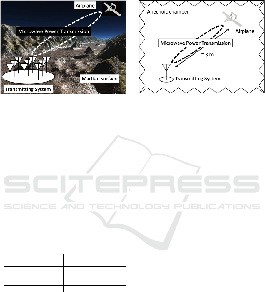
Figure 1: Conceptual image of a Mars observation airplane
driven by microwave power transmission.
2 SYSTEM REQUIREMENTS OF
TERRESTRIAL EXPERIMENTS
Specifications of Mars observation airplane under
consideration are shown in Table 1. When we utilize
MPT for a Mars observation airplane, the power
required for a propeller motor must be transferred
continuously. Then the power density at the main
wing, on which rectennas will be mounted, is
estimated to be 818 W/m
2
, assuming that the rf-dc
conversion efficiency of the rectenna is 63 %. Since
we cannot conduct MPT from such a long distance of
100 m as a feasibility study, the estimated power
density becomes the criterion for the power density of
terrestrial MPT experiments.
Table 1: Specifications of Mars observation airplane (under
consideration).
Airplane weight 1.81 kg
Velocity 50.9 m/s
Main wing area 0.256 m
2
Power required for
motor
132 W
Flight altitude Order of 100 m
The objective of terrestrial experiments is to
realize battery-less stable flight by MPT. A schematic
of the terrestrial experiments is shown in Figure 2.
The experiments were conducted in an anechoic
chamber and the distance from the transmitting
system to a prototype airplane is about 3 m. Under
the configuration, kW-class microwave power is
necessary to meet the required power density. We
therefore adopt magnetron, which is available for
microwave oven, as microwave generator.
Figure 2: Schematic of terrestrial MPT experiments to a
prototype airplane.
3 MAGNETRON-BASED
MICROWAVE TRANSMITTING
SYSTEM
The transmitting frequency of MPT must be fixed
from the viewpoint of rectenna design with high rf-dc
conversion efficiency. Also the output power must be
controlled to realize stable flight because the distance
between the transmitting systems and the airplane
fluctuate constantly. Moreover, the output phase of
each transmitting antenna element must be controlled
when we introduce phased array for the transmitting
system. However a magnetron is a free-running
oscillator and its frequency shifts by its driving
current (anode current), temperature and output load.
We therefore developed a power-variable phase-
controlled magnetron (PVPCM). A great feature of
PVPCM is that its output power can be controlled
with keeping its frequency and phase locked to those
of reference signal. A schematic diagram of a
PVPCM is shown in Figure 3. An injection locking
method (Sivan, 1994) is used for locking the
magnetron frequency to the reference signal
frequency. Also phase synchronization is realized by
comparing phases of the magnetron output and the
reference signal and adjusting the reference signal
phase via the phase shifter 2. The phase shifter 1 is
used for controlling the microwave beam direction
when we apply phased array to the transmitting
system.
We succeeded in developing a PVPCM, whose
frequency was fixed at 2.44575 GHz and whose
output power could be controlled from 450 W to 860
W (Nagahama, 2011).
Third International Conference on Telecommunications and Remote Sensing
48
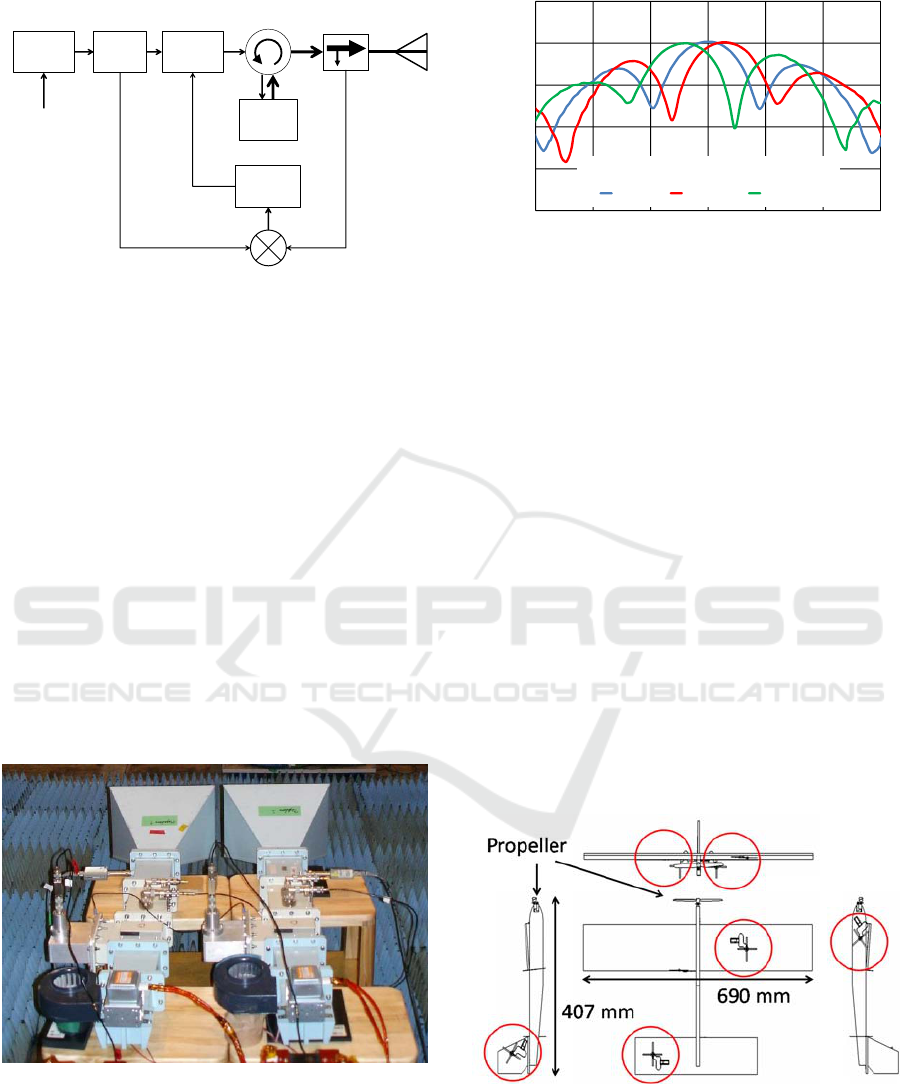
Figure 3: Schematic diagram of a power-variable phase-
controlled magnetron (PVPCM).
We demonstrated microwave beam forming by a
phased array composed of two PVPCMs. Figure 4
shows a photograph of the PVPCM phased array.
Two PVPCMs were set in a horizontal plane. The
horn antenna spacing was 0.409 m.
Figure 5 shows experimental results of
microwave beam patterns by the PVPCM phased
array. When two PVPCMs were in phase, the
microwave beam was focused on the broadside
direction. We confirmed that the beam direction was
controlled by setting the phase difference between
two PVPCMs. We obtained the antenna gain of 20
dBi including array factor and element factor of horn
antenna. Also we confirmed that we could adjust the
power density at the receiving point by controlling the
output power.
Figure 4: Photograph of a PVPCM phased array. The
phased array was composed of two PVPCMs.
Figure 5: Experimental results of microwave beam patterns
of the PVPCM phased array.
4 PROTOTYPE AIRPLANE
Figure 6 shows a schematic of a prototype airplane.
The prototype airplane was made of polystyrene foam,
and driven by a propeller attached to an electric motor.
The red circles in Figure 6 indicate the places where
rectennas were allocated. Six rectennas were mounted
on the airplane without interfering with each other in
the light of electromagnetic field.
Figure 7 shows a photograph of our developed
rectenna. The rectenna consisted of cross dipole
antenna and rectifying circuit. The cross dipole
antenna was chosen because it can receive sufficient
microwave power even under a various attitude of the
airplane. The measured rf-dc conversion efficiency of
the rectrenna was 63 % when the output load was 100
Ω (Nagahama, 2012). On the airplane, all the
rectennas were connected in pallalel for the purpose
of impedance matching with the electric motor.
Figure 6: Schematic of a prototype airplane. The red circles
indicate the places where rectennas were allocated.
Reference
Signal
(2.45GHz)
Phase
Shifter1
Phase
Shifter2
Power
divider
Magne‐
tron
IF
RFLO
Lowpass
filter
Circulator
Directional
coupler
Mixer
‐20
‐10
0
10
20
30
60 70 80 90 100 110 120
Gain (dBi)
Azimuthangle(deg.)
0deg. 90deg. 270deg.
Phasedifferencebetweentwo PVPCMs
Feasibility Study on Microwave Power Transmission to an Airplane for Future Mars Observation
49
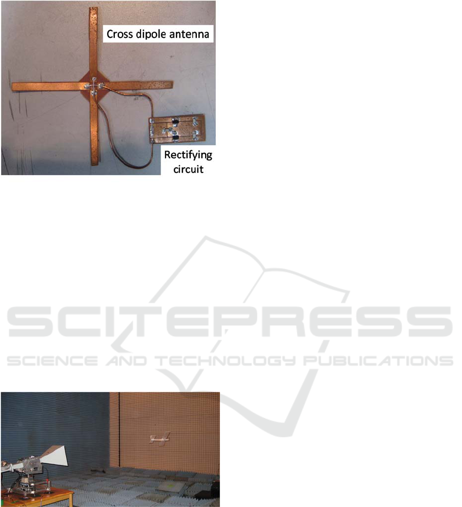
Figure 7: Photograph of a rectenna. The rectenna was
composed of cross dipole antenna and rectifying circuit.
5 DEMONSTRATION FLIGHT
We conducted two types of demonstration flight in
the anechoic chamber: straight flight and circular
flight. Figure 8 shows a photograph of the
demonstration of circular flight. In both cases, the
transmitting system was composed of a single
magnetron and horn antenna. The horn antenna
direction was mechanically controlled towards the
prototype airplane. The output power was 800 W. In
the case of circular flight, the prototype airplane was
suspended from above by gut. We confirmed that the
prototype airplane was driven by MPT in both cases.
Figure 8: Photograph of demonstration flight. The
transmitting system was composed of a single magnetron.
The transmitting antenna direction was mechanically
controlled towards the prototype airplane.
6 CONCLUSION
We succeeded in demonstration flight of the
prototype airplane by MPT without battery and fuel.
Adoption of phased array for the transmitting system
will be the next step for a long-distance and long-time
flight. Precise direction detection of the prototype
airplane will be also necessary to realize autonomous
flight.
ACKNOWLEDGEMENTS
This work was supported by JSPS KAKENHI, Grant-
in-Aid for Challenging Exploratory Research, Grant
Number 25630391.
REFERENCES
Iwashimizu, M., Mitani, T., Shinohara, N., Sasaki, G.,
Hiraoka, K., Matsuzaki, K., Yonemoto K., 2014. Study
on Direction Detection in a Microwave Power
Transmission System for a Mars Observation Airplane.
In IEEE Wireless Power Transfer Conference (WPTC
2014).
Nagahama, A., Mitani, T., Shinohara, N., Fukuda, K.,
Hiraoka, K., Yonemoto K., 2012. Auto Tracking and
Power Control Experiments of a Magnetron-based
Phased Array Power Transmitting System for a Mars
Observation Airplane. In 2012 IEEE MTT-S
International Microwave Workshop Series (IMWS) on
Innovative Wireless Power Transmission:
Technologies, Systems, and Applications (IMWS-IWPT
2012).
Nagahama, A., Mitani, T., Shinohara, N., Tsuji, N., Fukuda,
K., Kanari, Y., Yonemoto K., 2011. Study on a
Microwave Power Transmitting System for Mars
Observation Airplane. In 2011 IEEE MTT-S
International Microwave Workshop Series (IMWS) on
Innovative Wireless Power Transmission:
Technologies, Systems, and Applications (IMWS-IWPT
2011).
Sivan, L., 1994. Microwave Tube Transmitters, Chapman
& Hall, London.
Third International Conference on Telecommunications and Remote Sensing
50
