
Using UML to Specify Artifact-centric Business Process Models
Montserrat Esta
˜
nol
1
, Anna Queralt
2
, Maria-Ribera Sancho
1,2
and Ernest Teniente
1
1
Universitat Polit
`
ecnica de Catalunya, Jordi Girona 1-3, 08034 Barcelona, Spain
2
Barcelona Supercomputing Center, Jordi Girona 31, 08034 Barcelona, Spain
{estanyol, ribera, teniente}@essi.upc.edu, anna.queralt@bsc.es
Keywords:
Business Artifacts, BALSA Framework, UML, Business Process Modeling
Abstract:
Business process modeling using an artifact-centric approach has raised a significant interest over the last
few years. One of the research challenges in this area is looking for different approaches to represent all the
dimensions in artifact-centric business process models. Bearing this in mind, the present paper proposes how
to specify artifact-centric business process models by means of diagrams based on UML. The advantages of
basing our work on UML are many: it is a semi-formal language with a precise semantics; it is widely used
and easy to understand; and it provides an artifact-centric specification which incorporates also some aspects
of process-awareness.
1 INTRODUCTION
Business process models have been traditionally
based on an activity-centric or process-centric per-
spective, defining how a business process or workflow
is supposed to operate, but giving little importance to
the information produced or needed by the process
(Damaggio et al., 2011).
In contrast, the artifact-centric (or data-centric)
approach to process modeling considers data as a
key element in the business process specification.
Business artifacts, representing the data, model key
business-relevant entities which are updated by a set
of services that implement business process tasks.
The main advantage of artifact-centric business pro-
cess models over process-centric approaches is that
it is possible to perform semantic reasoning on the
model. That is, the meaning of the tasks can be for-
mally defined and it is possible to automatically check
for any inherent contradictions in their definition. The
artifact-centric approach to business process model-
ing has been successfully applied in practice (Bhat-
tacharya et al., 2007a) and it has been shown to have
a great intuitive appeal to business managers and to
system developers.
To facilitate the analysis of artifact-centric pro-
cess models, (Hull, 2008; Bhattacharya et al., 2009)
proposed the use of the BALSA (Business Artifacts,
Lifecycles, Services and Associations) framework.
This framework establishes the common ground for
artifact-centric business process modeling by defin-
ing four different dimensions which, ideally, should
be present in any artifact-centric process model:
• Business Artifacts. They represent meaningful
data for the business, and as such they hold infor-
mation needed for the process. Each artifact cor-
responds to a real life entity, and therefore may be
related to other business artifacts. A business ar-
tifact has an identity and its progress through the
workflow can be tracked.
• Lifecycles. Lifecycles represent the evolution of
an artifact, showing the relevant stages in its life,
from the moment it is created until it is destroyed
or archived.
• Services. They represent tasks (i.e. meaningful
units of work) that evolve the artifact in order to
achieve the process’s goals. They create, update
and delete business artifacts.
• Associations. Associations represent constraints
in the manner how services make changes to ar-
tifacts. This means that associations can restrict
the order in which services are executed. They
may be specified using a procedural specification
(e.g. a workflow) or in a declarative way (e.g.
condition-action rules).
Notice that, for the remainder of this work, we use the
term service with the meaning defined above, which
differs from its definition in Service Science.
One of the research challenges in artifact-centric
business process modeling is to find the “best” model
84
EstaÃ
´
sol M., Queralt A., Sancho M. and Teniente E.
Using UML to Specify Artifact-centric Business Process Models.
DOI: 10.5220/0005424600840093
In Proceedings of the Fourth International Symposium on Business Modeling and Software Design (BMSD 2014), pages 84-93
ISBN: 978-989-758-032-1
Copyright
c
2014 by SCITEPRESS – Science and Technology Publications, Lda. All rights reserved

(Hull, 2008), seeing that none of the existing ap-
proaches can handle the number of requirements of
business process modeling. After an extensive analy-
sis, we realized that the majority of work that has been
done in this area is based on complex mathematical
or logical languages to represent the processes. Al-
though they are practical from a formal perspective,
these languages are difficult to understand and not in-
tuitive for business people.
For this reason, in this paper we propose a way
to represent artifact-centric business process models
such that:
• It is a high-level representation.
• It is independent from the final implementation of
the business process.
• It represents most of the BALSA dimensions in a
graphical, intuitive way.
We do so by mapping each of the dimensions in
the BALSA framework to a graphical model, if pos-
sible. We will define these models using the UML
language as a basis because of its expressiveness, al-
though they could be defined using a different nota-
tion. UML is an ISO standard (ISO, 2012) and it is
also the de facto standard for software modeling. Al-
though initially conceived for software modeling, we
have found that it adapts easily to artifact-centric busi-
ness process modeling, as we can use it to represent
both the static structure and the dynamic behavior of
the process. Those aspects that cannot be represented
graphically using UML will be specified using OCL
(Object Constraint Language) (ISO, 2012). Although
they could be represented using another language, we
use OCL because it integrates naturally with UML
and it does not have the ambiguities of natural lan-
guage.
This paper extends our previous work in (Esta
˜
nol
et al., 2013) by describing in detail the characteristics
of the models we use to define artifact-centric busi-
ness process models using UML as a basis. We also
provide a detailed comparison of our proposal to pre-
vious work, and we include some process-centric ap-
proaches in the review.
The rest of the paper is structured in the follow-
ing way. Section 2 presents our proposal for artifact-
centric business process models using UML. In order
to illustrate it, we will use a running example based
on a city bicycle rental system. Section 3 analyzes
and reviews the related work. Finally, section 4 states
the conclusions and describes some further work.
2 ARTIFACT-CENTRIC
BUSINESS PROCESS MODELS
IN UML
One of the pending challenges in artifact-centric busi-
ness process modeling is to find the best model to rep-
resent each of the dimensions of the BALSA frame-
work (Hull, 2008). This section describes in de-
tail how UML and OCL can be applied to define an
artifact-centric process model following this frame-
work. From this process we obtain a platform-
independent model (a term we borrow from model-
driven architecture to refer to a model that is indepen-
dent of the final implementation platform) which is
detailed enough to show how the artifacts evolve and
the effect of services on them.
Business
Artifacts
Lifecycles
Services
Associations
Figure 1: Generic representation of the dimensions in the
BALSA framework.
Figure 1, adapted from (Hull, 2008), shows the
different BALSA dimensions and how they relate to
each other. We start by defining the business arti-
facts and how they are related to other objects. More
specifically, we will determine their attributes, the re-
lationships between them, and their identifiers (for
both the artifacts and the objects). Once we have this,
for each business artifact, we will define its lifecycle.
This should give us an overview of the different events
that trigger the transitions between states. After this,
it is time to specify the services that make up these
events and to establish the conditions or the order of
their execution (i.e. the associations).
We will illustrate our approach by means of a real-
life example, based on a city bicycle rental system,
such as Bicing. Bicing is a service offered by the
Barcelona City Council to registered users as an al-
ternative form of transport. Bicycles are docked to
stations placed around the city, so that users can take
a bicycle form a certain station and return it to a differ-
ent one. For the purpose of our example, we will con-
Using UML to Specify Artifact-centric Business Process Models
85

sider that users are automatically blacklisted if they
do not return a bicycle within three days after taking
it.
2.1 Business Artifacts as a Class
Diagram
Business artifacts represent the relevant data for the
business. A business artifact has an identity, which
makes it distinguishable from any other artifact, and
can be tracked as it progresses through the workflow
of the business process execution. It will also have a
set of attributes to store the data needed for the work-
flow execution. Business artifacts may be related to
other business artifacts and objects. The main differ-
ence between a business artifact and an object is that
the business artifact has an associated lifecycle show-
ing its evolution, whereas the object does not. In busi-
ness terms, an artifact represents the explicit knowl-
edge concerning progress toward a business goal at
any instant.
The conceptual schema of business artifacts is in-
tended to hold all the information needed to complete
business process execution. Business artifacts and ob-
jects are similar to domain concepts because they rep-
resent real-world entities. As domain concepts can be
represented in a class diagram, we will be able to rep-
resent business artifacts and objects in the same way.
In particular, we will use a class diagram based on
UML, which will allow us to represent, in a graphical
way, the following elements:
• Classes, which correspond to business artifacts or
objects.
• Attributes for each of the classes, which contain
relevant information for each domain concept.
• Relationships between classes, showing how
they relate to each other.
• Integrity Constraints, which establish restric-
tions over the classes, the attributes or the rela-
tionships between them. Constraints can be rep-
resented either graphically, in the diagram itself,
or textually in OCL or in natural language.
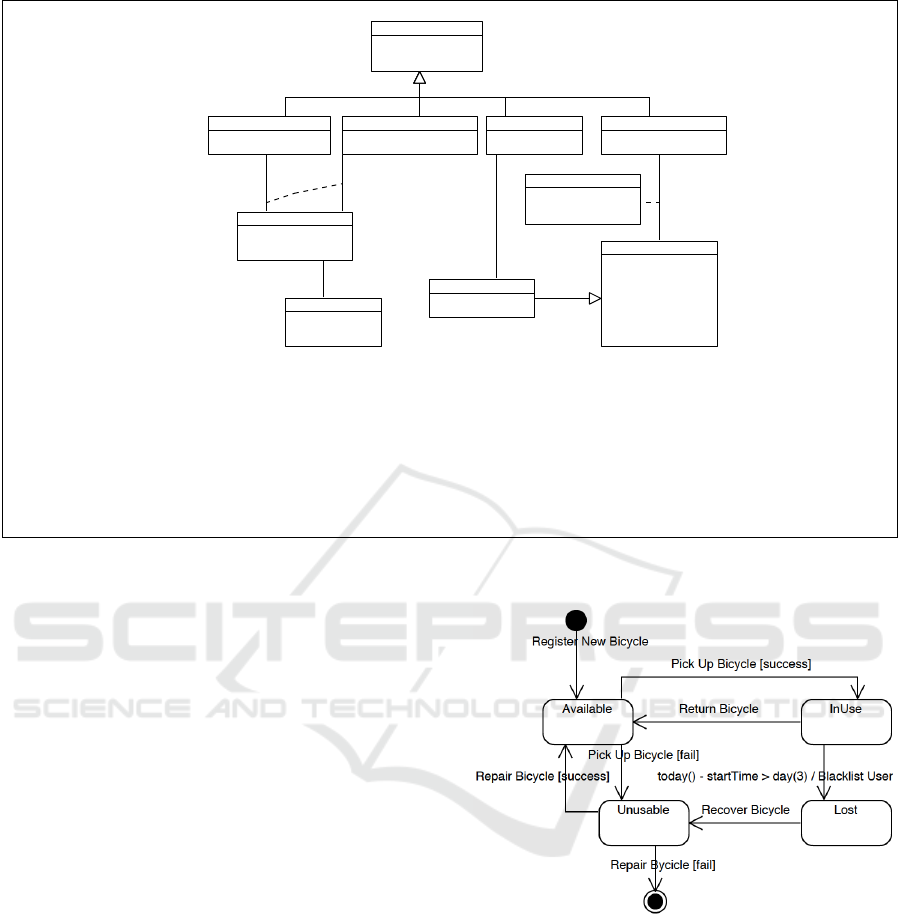
Figure 2 shows the class diagram that corresponds
to our bicycle rental system example. The business
artifact in our example is Bicycle, as it keeps the in-
formation of the key elements needed to provide the
service: the bicycles themselves, which are identified
by their id. Apart from the business artifact, there
are several objects, such as AnchorPoint (identified by
number and Station, according to constraint 3), User
(identified by id) and Station (also identified by id).
For each artifact or object, we will have as many at-
tributes as relevant information we want to keep about
it.
The evolution of a business artifact is recorded in
the class diagram by means of subclasses. The use
of subclasses makes it possible to have exactly the at-
tributes and relationships that are needed according
to the artifact’s state, preserving at the same time its
original identifier and the characteristics that are in-
dependent of the artifact’s state which are represented
in the superclass.
In our example, the business artifact Bicycle has
four subclasses: Available, InUse, Lost and Unusable
which keep track of the different stages of the Bicycle
while containing information which is relevant only
for that particular stage. For instance, when a bicy-
cle is InUse, it is linked to a certain User and has
an attribute that stores when it is expected to be re-
turned. These subclasses also require restrictions to
ensure that the dates are coherent: we do not show
each of the restrictions due to space limitations.
Notice that BicycleRental is an association class:
it results from the reification of a relationship (i.e.
viewing it as class) between two or more classes
(Oliv
´
e, 2007). Association classes are particularly
useful when we want to record additional information
about a relationship, as it is the case here. They are
identified by the classes that take part in the relation-
ship; in this case, InUse and User (identified by its
id).
2.2 Lifecycles as State Machine
Diagrams
The lifecycle of a business artifact states the relevant
stages in the possible evolution of the artifact, from
inception to final disposal and archiving, as far as the
business process is concerned. It is natural to rep-
resent it by using a variant of state machines, where
each state of the machine corresponds to a possible
stage in the lifecycle of an artifact from the class dia-
gram (Hull, 2008).
Therefore, for each business artifact in our class
diagram, we will have the corresponding state ma-
chine diagram representing its lifecycle. Taking as
a basis UML state machine diagrams, our diagrams
consist of:
• States. They represent the stages in the evolu-
tion of a class or business artifact. Therefore, a
state machine diagram will have as many states as
relevant subclasses the business artifact has in the
class diagram.
• Transitions. Transitions, represented as arrows,
connect the different states (i.e. stages of the busi-
Fourth International Symposium on Business Modeling and Software Design
86
id : String
inServiceSince : Date
Bicycle
id : String
name : String
email : String
dateOfBirth : Date
creditCard : Natural
validUntil : Date
User
number : Natural
locked : Boolean
AnchorPoint
startTime : DateTime
confirmed : Boolean
BicycleRental
expectedReturn : Date
InUse
unsusableSince : Date
Unusable
date : Date
Lost
date : Date
BlacklistedUser
lastReturn : Date [0..1]
Available
id : String
address : String
Station
BicycleState
1
0..1
responsible
0..1
1
1
0..1
0..1
1
1..*
1
has lost
belongs to
{xor}
{disjoint, complete}
unusable bike is in
is in
Visual Paradigm for UML Community Edition [not for commercial use]
1. Bicycles are identified by their id: context Bicycle inv: Bicycle.allInstances()-> isUnique(id)
2. Users and Stations are identified by their respective id: See restriction 1.
3. A Station cannot have two AnchorPoints with the same number:
context Station inv: self.anchorPoint->isUnique(number)
4. A BlacklistedUser cannot have any BicycleRentals: context BlacklistedUser inv: self.bicycleRental->isEmpty()
5. Dates should be coherent: Several OCL constraints would be required.
Figure 2: Class diagram showing the business artifacts as classes with the corresponding integrity constraints.
ness artifact) in the state machine diagram. Tran-
sitions may have the following elements:
– Guard Constraints. They are conditions
which must be true to trigger a transition be-
tween two different states. However, if there is
an event in the transition, the event must take
place and the condition must be true in order
for the transition to be triggered.
– Events: Events represent noteworthy occur-
rences that may trigger a transition between
states. If there is no condition, the transition
will be triggered when the event occurs; other-
wise, the condition must also be true when the
event takes place. We will distinguish between
two types of event:
∗ Internal Events. They correspond to condi-
tions stated over the content of the business ar-
tifacts or objects, or over time, and may cause
the execution of actions without requiring the
user’s intervention. They are referred to as
change or time events in (Oliv
´
e, 2007).
∗ External Events. They are explicitly re-
quested by the customer of the business pro-
cess and their behavior is specified by means
of a set of associated services. Therefore, ex-
ternal events are non-atomic. They roughly
correspond to call or signal events in (Oliv
´
e,
2007).
Figure 3: State machine diagram for Bicycle.
These events may be accompanied by an event-
dependent condition. These conditions are
placed after the event as they indicate how said
event must end in order for the transition to be
triggered.
– Actions. Actions are automatically executed
when the transition fires.
The state machine diagram for the key artifact Bi-
cycle in our example is shown in Figure 3. Notice that
each subclass of Bicycle in the class diagram in Fig-
ure 2 now corresponds to a stage in the state machine
diagram.
Using UML to Specify Artifact-centric Business Process Models
87

A Bicycle is created when it is registered in the
system. Initially it is in state Available. From the
Available state, a bicycle may become InUse, if a
User picks it up successfully, or Unusable, if he does
not (the bicycle may be broken or damaged). Notice
that both transitions are triggered by external event
Pick Up Bicycle, and the final state depends on the
event-dependent condition of this event. From state
InUse, a bicycle will become Available again when
the user returns it.
When a bicycle is Unusable, it needs to be re-
paired (Repair Bicycle) in order to become available
again. There are two possible outcomes. If the bi-
cycle is repaired successfully (event-dependent con-
dition success) it changes its state to Available. If,
on the other hand, it is beyond repair, the bicycle is
destroyed.
Finally, notice that if a bicycle is not returned for
three days after it is picked up (internal event today()
− startTime > day(3)), action Blacklist User is exe-
cuted and the bicycle changes its state to Lost. If at
any time the bicycle is recovered (Recover Bicycle),
then it changes to state Unusable, as it will have to be
revised and repaired before it can be used again.
We would like to point out that this diagram does
not follow exactly the standard described in (ISO,
2012). This is due to the fact that our state machine
diagram has event-dependent conditions, which we
use to determine whether the event ends successfully
or not. In traditional UML state machine diagrams,
events are atomic and there is no need for such condi-
tions.
In addition to this, we also allow having more than
one outgoing transition from the initial node. This
is useful when the artifact can be created in differ-
ent ways. Alternatively, this situation could be repre-
sented using one outgoing transition from the initial
node, leading to a state called InitialState. From this
state, we could have the outgoing transitions that start
from the initial node and leave the rest of the state
machine diagram as it is. However, representing the
lifecycles in this way does not contribute any relevant
information and adds complexity to the final diagram.
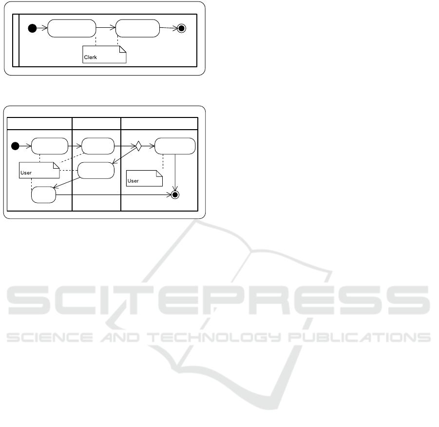
2.3 Associations as Activity Diagrams
As we have just mentioned, external events and ac-
tions in a state machine diagram are non-atomic and
consist of a set of services. Consequently, for each ex-
ternal event and action in a state machine diagram we
need to specify the services it consists of and the as-
sociations between them. Associations in the BALSA
framework establish the conditions under which ser-
vices may execute.
We propose to specify associations using UML ac-
tivity diagrams as a basis. Therefore, we will define
one such diagram for each external event and action
in a state machine diagram. Then, for the state ma-
chine diagram in Figure 3, we would have an activity
diagram for the following external events: Register
New Bicycle, Pick Up Bicycle, Return Bicycle, Repair
Bicycle and Recover Bicycle. We would also have an
activity diagram for action Blacklist User.
The main elements of activity diagrams are the
following:
• Nodes. We will distinguish between two types of
nodes:
– Tasks.
1
: Tasks represent the work that has to be
done. In most cases, each task corresponds to a
service (as defined in the BALSA framework).
However, tasks with a rake-like symbol are fur-
ther decomposed in another activity diagram.
This is particularly useful to reuse certain be-
haviors. It is the responsibility of the business
process modeler to decide how many tasks and
services are needed to specify the behavior of
an external event or action. Understandabil-
ity of the diagrams defined is the criterion that
should guide this decision.
– Control Nodes. They are used to manage the
flow. Examples of control nodes are decision
and merge nodes. Decision nodes indicate that
only one of the subsequent paths will be taken
according to a certain condition. Merge nodes,
on the other hand, indicate that the execution of
the activity diagram continues after one of its
incoming edges carries information. There are
other types of control nodes but we will focus
on these two.
• Edges. Edges connect the nodes among them and
establish the order for the execution of the tasks.
In addition to these, we will also use swimlanes,
on the one hand, and notes stereotyped as Partici-
pant, on the other hand. Although not strictly nec-
essary, swimlanes will provide additional information
by indicating the main business artifact or object that
is involved in each of the tasks and whether the cor-
responding task deals with material or informational
resources. Material tasks deal with physical elements
and are represented using stereotype material in the
swimlane or in the task itself. Informational tasks,
on the other hand, deal with the representation of the
1
Tasks are actually called actions in the terminology of
UML activity diagrams. However, in order to avoid confu-
sion with actions in state machine diagrams, we will refer
to them as tasks throughout this document.
Fourth International Symposium on Business Modeling and Software Design
88
ActivityDiagram
Register New Bicycle
Return Bicycle
Repair Bicycle
Pick Up for Repair [DEPRECATED]
Pick Up Bicycle
<<material>>
Place Bicycle in
Anchor Point
Confirm Bicycle
Return
<<material>>
Repair Bicycle
Mark Bicycle
as Available
Delete
Bicycle
<<material>>
Dismantle Bicycle
<<material>>
Anchor Bicycle to
Anchor Point
Change Status to
BeingRepaired
<<material>>
Move Bicylce to
Warehouse
Bicycle
Bicycle
<<material>>
Bicycle
BicycleRental
Assign to
AnchorPoint
Create New Bicycle
<<Participant>>
Request Bicycle
Get Bicycle
Confirm
Return
Confirm Pick-Up
Return to
Anchor Point
<<Participant>>
<<Participant>>
<<fail>>
[impossible to repair]
<<succeed>>
[repaired]
<<fail>>
[bad shape]
[ok]
<<succeed>>
Visual Paradigm for UML Community Edition [not for commercial use]
Figure 4: Activity diagram for Register New Bicycle.
Pick Up Bicycle
Bicycle
<<material>>
Bicycle
BicycleRental
Request Bicycle
Get Bicycle
Confirm
Return
Confirm Pick-Up
Return to
Anchor Point
<<Participant>>
<<Participant>>
<<fail>>
[bad shape]
[ok]
<<succeed>>
Figure 5: Activity diagram for Pick Up Bicycle.
real-life artifact or object. They are shown in the
activity diagram as tasks without stereotypes in the
swimlane. This distinction is important, because we
will only be able to specify services that deal with in-
formational resources and not material ones.
Moreover, we will use notes with stereotype Par-
ticipant to show the role/s of the people who carry out
a particular task.
Figure 4 shows the activity diagram of Register
New Bicycle. First of all, the clerk provides the infor-
mation of the new bicycle and, after this, he assigns
it to an anchor point. The main artifact involved in
both services is the Bicycle. In this particular case,
both tasks are atomic and deal with information and
not material resources.
Figure 5 represents the activity diagram of Pick
Up Bicycle. The user first requests a bicycle to the
system and then he physically picks it up from its an-
chor point. If the bicycle is not in good shape, he
returns it to an anchor point and then he confirms the
return. Notice that in this case the activity diagram
ends in failure. On the other hand, if the bicycle is
usable, he takes it with him and confirms the return.
Then the activity diagram ends successfully. It is im-
portant to make this distinction between success and
failure as depending on the result of the activity dia-
gram, the bicycle will change to state InUse or Unus-
able, as shown in Figure 3.
In this particular diagram, there are two tasks or
services that deal with material resources: Get Bicy-
cle and Return to Anchor Point, which correspond to
physically getting the bicycle from its anchor point
and placing it on the anchor point, respectively.
Notice that the approach that we follow to specify
associations is procedural in the sense that the activ-
ity diagrams define a clear order for the execution of
services. In contrast, most artifact-centric proposals
follow a declarative approach where associations de-
fine the conditions under which services may be exe-
cuted. Our use of activity diagrams to specify associa-
tions brings it closer to process-centric methodologies
while keeping its artifact-centric nature.
2.4 Services as Operation Contracts
In the context of the BALSA framework, a service
is a unit of work meaningful to the whole business
process. Services create, update and delete business
artifacts. In turn, this may make artifacts evolve to a
new stage meaningful from the business perspective.
In our approach, services correspond to the informa-
tional and atomic tasks in the activity diagrams.
UML does not have a way to represent services
graphically. Instead, they are defined by an operation
contract which states what the service does. Opera-
tion contracts consist of a set of input parameters and
output parameters, a precondition and a postcondi-
tion. Both input and output parameters can be classes
(i.e. business artifacts or objects) or simple types (e.g.
integers, strings, etc.). A precondition states the con-
ditions that must be true before invoking the operation
and refers to the values of attributes at the time when
the service is called. The postcondition indicates the
state of the business artifacts or objects after the ex-
ecution of the operation. Those artifacts and objects
that do not appear in the postcondition keep their state
from before the execution of the operation. To avoid
redundancies with the integrity constraints of the class
diagram we assume a strict interpretation of operation
contracts (Queralt and Teniente, 2006).
These operation contracts might be specified by
means of different languages, such as natural lan-
guage. However, the resulting specification would be
ambiguous since it would allow for multiple interpre-
tations. Therefore, we propose to specify services us-
ing operation contracts defined in OCL. As we have
already mentioned, OCL is a formal language that
avoids ambiguities. Moreover, it is declarative, which
means that it does not indicate how things should be
done, but rather what should be done.
We have shown in Figure 4 that the external event
Register New Bicycle is performed by means of two
services (i.e. tasks): Create New Bicycle and Assign
to Anchor Point, which are informational and atomic.
Therefore, we need to specify an operation contract
for each such service.
Using UML to Specify Artifact-centric Business Process Models
89

Listing 1: Code for action CreateNewBicycle.
action CreateNewBicycle ( bId: String): Bicycle
localPre: -
localPost :
Bicycle . allInstances ()-> exists (b | b. oclIsNew ()
and b.id=bId and b.oclIsTypeOf( Available)
and b.inServiceSince = today() and result=b)
Listing 1 shows the operation contract of service
Create New Bicycle. It has as input parameter the id
of the Bicycle that we are adding to the system. The
service creates a new bicycle in state Available with
the given id.
Listing 2: Code for action AssignToAnchorPoint.
action AssignToAnchorPoint (b: Bicycle , apNumber:
Natural , stationId: String )
localPre: -
localPost :
b.oclAsType ( Available ).anchorPoint =
AnchorPoint() . allInstances () -> select ( ap |
ap. number=apNumber and
ap. station .id= stationId)
Listing 2 shows the OCL code for AssignToAn-
chorPoint. Given a Bicycle and the identifiers of an
AnchorPoint (AnchorPoint number and Station id) as
input parameters, it assigns the bicycle to the corre-
sponding AnchorPoint. Notice that both the operation
contracts in Listings 1 and 2 have no preconditions in
order to avoid redundancies. For instance, Listing 2
does not check whether there exists an AnchorPoint
with the given identifiers.
3 RELATED WORK
This section identifies and examines different alterna-
tives to represent the four dimensions in the BALSA
framework. We will mainly focus on artifact-centric
approaches, although we will also give an overview
of process-centric approaches.
3.1 Artifact-centric Approaches
Although not all researchers who work with artifact-
centric business process models specifically use the
BALSA framework, it is not difficult to establish a
correspondence between their system of representa-
tion and the dimensions in the framework. Therefore,
in order to facilitate the analysis of the existing alter-
natives, the subsection has been structured according
to these dimensions.
Business Artifacts. Business artifacts, sometimes
referred to as business entities, are represented in
different ways in the literature. Various authors
use database schemas (Bagheri Hariri et al., 2011;
Bagheri Hariri et al., 2013; Belardinelli et al., 2011;
Cangialosi et al., 2010). A similar representation is
proposed in (Bhattacharya et al., 2007b; Damaggio
et al., 2012; Fritz et al., 2009; Nigam and Caswell,
2003) where artifacts consist of a set of attributes or
variables. Another alternative is to add an ontology
represented by means of description logics on top of
a relational database (Calvanese et al., 2012). None
of these representations is graphical; therefore, this
makes them more intricate and more difficult to un-
derstand at a glance. For instance, it is complex to see
the relationships between the different artifacts.
On the other hand, (Bhattacharya et al., 2009;
Fahland et al., 2011; Hull et al., 2011b; Hull et al.,
2011a; Damaggio et al., 2013; Lohmann and Wolf,
2010) use different graphical and formal represen-
tations for business artifacts. (Lohmann and Wolf,
2010) chooses to represent artifacts as state machine
diagrams defined by Petri nets. However, little at-
tention is given to the way the attributes are repre-
sented, as the paper is focused on adding the concepts
of agent and location to artifact-centric process mod-
els. Conversely, (Hull et al., 2011b; Damaggio et al.,
2013; Hull et al., 2011a) represent the business ar-
tifact and its lifecycle in one model, GSM, that in-
cludes the artifact’s attributes. The drawback of us-
ing GSM is that the relationships between artifacts
are not made explicit. Another alternative is using
an Entity-Relationship model as it is done in (Bhat-
tacharya et al., 2009). (Fahland et al., 2011) repre-
sents the data model of their example by means of
an UML class diagram. Both (Fahland et al., 2011;
Bhattacharya et al., 2009) use a graphical and formal
notation to represent the artifacts’ attributes and their
relationships, making them easier to understand.
Lifecycles. When it comes to defining the lifecycle
of business artifacts, there are two main alternatives:
existing approaches either offer an explicit represen-
tation of the evolution of the artifact or it is implicit.
The lifecycle may be implicitly represented by dy-
namic constraints expressed in logic (Bagheri Hariri
et al., 2011) or the actions that act upon artifacts
(Belardinelli et al., 2011; Cangialosi et al., 2010;
Bagheri Hariri et al., 2013; Calvanese et al., 2012).
On the other hand, explicit representations are
normally based on a state machine diagram. An ex-
ample is (Bhattacharya et al., 2009). State machine
diagrams provide a clear representation of the evolu-
tion of an artifact, showing the different stages in its
Fourth International Symposium on Business Modeling and Software Design
90

lifecycle and how each stage is reached.
A similar alternative to state machine diagrams
is GSM, first described in (Hull et al., 2011b) and
further studied and formalized in (Damaggio et al.,
2013; Hull et al., 2011a). Like state machine dia-
grams, GSM allows representing graphically guards
and stages. However, it adds the concept of mile-
stone to represent conditions that determine the clos-
ing of a state. On the other hand, the sequencing of
stages in the lifecycle of the artifact is determined
by guard conditions instead of edges connecting the
stages, making it much less visual and straighforward.
Nevertheless, it is possible to use edges as a macro.
Another formal approach is the one used in
(Fahland et al., 2011; Lohmann and Wolf, 2010),
where lifecycles are represented in variants of Petri
nets. A similar alternative is proposed in (Kucukoguz
and Su, 2011), where ArtiNets (similar to Petri nets)
and DecSerFlow, a declarative language, are used
to represent the lifecycle of an artifact and its con-
straints. These Petri net variants offer an understand-
able graphical representation that is also formal.
Finally, another possibility is to use a variable in
the artifact which stores its state (Damaggio et al.,
2012; Bhattacharya et al., 2007b). Although it is an
explicit representation, it only shows the current state
of the artifact, instead of showing how it will evolve
from one stage to the next. Therefore, it is a poorer
form of representation in contrast to state machine di-
agrams, variants of Petri nets or GSM.
Associations. Associations are represented in dif-
ferent ways depending on the approach of the pa-
per. Some authors opt for using condition-action
rules defined in logic (Bagheri Hariri et al., 2011;
Bagheri Hariri et al., 2013; Cangialosi et al., 2010;
Calvanese et al., 2012). (Bhattacharya et al., 2007b)
calls these conditions business rules; they should not
be confused with business rules in (Damaggio et al.,
2012), which are conditions that are superimposed in
the already existing ones. In (Damaggio et al., 2012),
preconditions determine the execution of the actions;
therefore, they act as associations. As in the case of
services, associations defined in logic have the advan-
tage of being formal and unambiguous; on the other
hand, they will be difficult to understand for the peo-
ple involved in the business process. In addition to
this, the fact that they are not represented in a graph-
ical way makes it more difficult to know, at a glance,
the order in which the services will or can be exe-
cuted.
Likewise, (Bhattacharya et al., 2009) uses event-
condition-action rules, but they are defined in natural
language. As we have already mentioned, using nat-
ural language makes them easier to understand, but
they are not formal and may have ambiguities. More-
over, like in the case of associations defined in logic,
it is difficult to know, at a glance, the order in which
services may be executed, as it is not a graphical rep-
resentation.
Alternatively, (Fahland et al., 2011) uses what the
authors call channels to define the connections be-
tween proclets. A proclet is a labeled Petri net with
ports that describes the internal lifecycle of an arti-
fact. Another option is DecSerFlow, that allows spec-
ifying restrictions on the sequencing of services, and
it is used in (Kucukoguz and Su, 2011). It is a lan-
guage grounded on temporal logic but also includes a
graphical representation. Therefore, both alternatives
are graphical and formal.
On the other hand, (Nigam and Caswell, 2003;
Bhattacharya et al., 2007a) opt for a graphical rep-
resentation using flowcharts. The advantage of us-
ing flowcharts is that they show, in a graphical and
straightforward way, the order in which services will
be executed, making them easy to understand. How-
ever, they do not use a particular language to define
the flow and little attention is given to the way of cre-
ating the flowchart.
Services. Services are also referred to as tasks or
actions in the literature. Despite the different termi-
nology, in general they are described by using pre and
postconditions (also called effects). Different vari-
ants of logic are used in (Bagheri Hariri et al., 2011;
Bagheri Hariri et al., 2013; Damaggio et al., 2012;
Bhattacharya et al., 2007b; Fritz et al., 2009; Belar-
dinelli et al., 2011; Calvanese et al., 2012) for this
purpose. The same idea is followed in (Cangialosi
et al., 2010; Damaggio et al., 2013) but omitting the
preconditions. Using logic means that the definition
of services is precise, formal and unambiguous, but
it has the problem of being difficult to understand for
the people involved in the process.
Conversely, (Bhattacharya et al., 2009) uses nat-
ural language to specify pre and postconditions. In
contrast to logic, natural language is easy to under-
stand, but it is an informal description of services: this
implies that the service definition may be ambiguous
and error-prone.
3.2 Process-centric Approaches
It is precisely because process-centric approaches fo-
cus on the order of the activities that have to be car-
ried out, that most alternatives only represent one of
the elements of the BALSA framework, the associa-
tions. As (Weske, 2007) shows, there are many differ-
Using UML to Specify Artifact-centric Business Process Models
91

ent languages to represent business processes from a
process-centric perspective such as BPMN, UML ac-
tivity diagrams, Workflow nets or YAWL. Although
some of these languages have the ability to represent
the data needed in the flow (even if in a limited way),
process-centric proposals focus on the ordering of the
activities or tasks and do not deal with the data.
However, in some cases they do take data into con-
sideration. For instance, (Trcka et al., 2009) repre-
sents the associations between services in a WFD-net
(WorkFlow nets annotated with Data). The annota-
tion of tasks in the WFD-Net can be seen as a rudi-
mentary way of specifying services, as it allows indi-
cating which data is created, read and written. Sim-
ilarly, (Ly et al., 2006) uses WSM nets which repre-
sent both the control flow and the data flow, although
the data flow is limited to read and write dependen-
cies between activities and data. In like manner, (Liu
et al., 2007) represents associations in an operational
model, which shows tasks (or services) as nodes con-
nected using arrows or edges. The operational model
also shows the transfer of artifacts between tasks by
indicating them over the edges. However, details of
artifacts are not shown.
3.3 Summary of Related Work
As we have seen, none of the approaches that we have
analyzed uses the same language to represent all the
elements in the BALSA framework, and many times
the chosen representation is not graphical, making the
models more difficult to grasp. This is aggravated by
the fact that, in some cases, the chosen language is a
variant of logic which, although formal, makes it next
to impossible for business people to comprehend. The
use of natural language also has its drawbacks: while
it may be easily understood, it may lead to ambigui-
ties and errors.
4 CONCLUSIONS
This paper shows a way to model all of the BALSA
dimensions in an artifact-centric business process
model using several diagrams based on UML. The use
of an activity diagram to represent the associations
between services brings it closer to process-centric
methodologies and makes it easier to understand than
condition-action rules defined in logic or even natural
language.
In contrast to other approaches, using diagrams
based on UML and OCL as a basis to represent all of
the dimensions of the model integrates them naturally.
Moreover, UML has several advantages: first of all, it
is a graphical, high-level language, and therefore the
resulting models are easy to understand by business
managers, analysts and developers. Secondly, UML
and OCL are standard languages. Last but not least,
both UML and OCL can be translated into logic (see
for instance (Queralt and Teniente, 2012)) in order to
facilitate reasoning on the resulting specification.
Finally, our proposal offers the advantages of a
graphical representation, understandable by the users,
without losing the capacity of being used for reason-
ing in the future since it is based on a semi-formal
notation that avoids ambiguities. As further work, we
would like to study the applicability of our approach
by analyzing the input provided by the business stake-
holders. We would also like to apply this work to
a business process model which has more than one
business artifact. Last but not least, we intend to de-
fine a way to perform automatic reasoning on our di-
agrams in order to validate their correctness, appro-
priateness and their quality before they are put into
practice.
ACKNOWLEDGEMENTS
This work has been partially supported by the
Ministerio de Ciencia e Innovaci
´
on under projects
TIN2011-24747 and TIN2008-00444, Grupo Consol-
idado, the FEDER funds and Universitat Polit
`
ecnica
de Catalunya.
REFERENCES
Bagheri Hariri, B., Calvanese, D., De Giacomo, G.,
De Masellis, R., and Felli, P. (2011). Foundations of
relational artifacts verification. In Rinderle-Ma, S.,
Toumani, F., and Wolf, K., editors, BPM 2011, vol-
ume 6896 of LNCS, pages 379–395. Springer.
Bagheri Hariri, B. et al. (2013). Verification of relational
data-centric dynamic systems with external services.
In PODS, pages 163–174. ACM.
Belardinelli, F., Lomuscio, A., and Patrizi, F. (2011). Veri-
fication of deployed artifact systems via data abstrac-
tion. In Kappel, G., Maamar, Z., and Nezhad, H.
R. M., editors, ICSOC 2011, volume 7084 of LNCS,
pages 142–156. Springer Berlin Heidelberg.
Bhattacharya, K., Caswell, N. S., Kumaran, S., Nigam, A.,
and Wu, F. Y. (2007a). Artifact-centered operational
modeling: lessons from customer engagements. IBM
Syst. J., 46(4):703–721.
Bhattacharya, K., Gerede, C., Hull, R., Liu, R., and Su, J.
(2007b). Towards formal analysis of artifact-centric
business process models. In Alonso, G., Dadam, P.,
and Rosemann, M., editors, BPM 2007, volume 4714
of LNCS, pages 288–304. Springer.
Fourth International Symposium on Business Modeling and Software Design
92

Bhattacharya, K., Hull, R., and Su, J. (2009). A Data-
Centric Design Methodology for Business Processes.
In Handbook of Research on Business Process Man-
agement, pages 1–28.
Calvanese, D., Giacomo, G. D., Lembo, D., Montali, M.,
and Santoso, A. (2012). Ontology-based governance
of data-aware processes. In Kr
¨
otzsch, M. and Straccia,
U., editors, RR, volume 7497 of LNCS, pages 25–41.
Springer.
Cangialosi, P., Giacomo, G. D., Masellis, R. D., and Rosati,
R. (2010). Conjunctive artifact-centric services. In
Maglio, P. P., Weske, M., Yang, J., and Fantinato, M.,
editors, ICSOC 2010, volume 6470 of LNCS, pages
318–333. Springer.
Damaggio, E., Deutsch, A., Hull, R., and Vianu, V. (2011).
Automatic verification of data-centric business pro-
cesses. In Rinderle-Ma, S., Toumani, F., and Wolf,
K., editors, BPM 2011, volume 6896, pages 3–16.
Springer.
Damaggio, E., Deutsch, A., and Vianu, V. (2012). Artifact
systems with data dependencies and arithmetic. ACM
Trans. Database Syst., 37(3):22.
Damaggio, E., Hull, R., and Vacul
´
ın, R. (2013). On the
equivalence of incremental and fixpoint semantics for
business artifacts with Guard Stage Milestone lifecy-
cles. Information Systems, 38(4):561 – 584. Special
section on BPM 2011 conference.
Esta
˜
nol, M., Queralt, A., Sancho, M. R., and Teniente, E.
(2013). Artifact-centric business process models in
UML. In La Rosa, M. and Soffer, P., editors, Business
Process Management Workshops 2012, volume 132 of
LNBIP, pages 292–303. Springer.
Fahland, D., Leoni, M. D., van Dongen, B. F., and van der
Aalst, W. M. P. (2011). Behavioral conformance of
artifact-centric process models. In Abramowicz, W.,
editor, BIS 2011, volume 87 of LNBIP, pages 37–49.
Springer.
Fritz, C., Hull, R., and Su, J. (2009). Automatic construc-
tion of simple artifact-based business processes. In
Fagin, R., editor, ICDT 2009, volume 361, pages 225–
238. ACM.
Hull, R. (2008). Artifact-centric business process mod-
els: Brief survey of research results and challenges.
In Meersman, R. and Tari, Z., editors, OTM 2008,
volume 5332 of LNCS, pages 1152–1163. Springer
Berlin / Heidelberg.
Hull, R. et al. (2011a). Business artifacts with guard-stage-
milestone lifecycles: managing artifact interactions
with conditions and events. In Eyers, D. M., Etzion,
O., Gal, A., Zdonik, S. B., and Vincent, P., editors,
DEBS, pages 51–62. ACM.
Hull, R. et al. (2011b). Introducing the Guard-Stage-
Milestone Approach for Specifying Business Entity
Lifecycles. In Bravetti, M. and Bultan, T., editors,
WS-FM 2010, volume 6551 of LNCS, pages 1–24.
ISO (2012). ISO/IEC 19505-2:2012 - OMG UML su-
perstructure 2.4.1. Available at: http://www.iso.org/
iso/iso catalogue/catalogue tc/catalogue detail.htm?
csnumber=52854.
ISO (2012). ISO/IEC 19507:2012 - OMG OCL ver-
sion 2.3.1. Available at: http://www.iso.org/
iso/iso catalogue/catalogue tc/catalogue detail.htm?
csnumber=57306.
Kucukoguz, E. and Su, J. (2011). On lifecycle constraints
of artifact-centric workflows. In Bravetti, M. and Bul-
tan, T., editors, WS-FM 2010, volume 6551 of LNCS,
pages 71–85. Springer.
Liu, R., Bhattacharya, K., and Wu, F. Y. (2007). Model-
ing Business Contexture and Behavior Using Business
Artifacts. In Krogstie, J., Opdahl, A., and Sindre, G.,
editors, CAiSE 2007, volume 4495 of LNCS, pages
324–339. Springer.
Lohmann, N. and Wolf, K. (2010). Artifact-Centric Chore-
ographies. In Maglio, P. P., Weske, M., Yang, J., and
Fantinato, M., editors, ICSOC 2010, volume 6470 of
LNCS, pages 32–46. Springer.
Ly, L. T., Rinderle, S., and Dadam, P. (2006). Semantic Cor-
rectness in Adaptive Process Management Systems.
In Dustdar, S., Fiadeiro, J., and Sheth, A., editors,
BPM 2006, volume 4102 of LNCS, pages 193–208.
LNCS.
Nigam, A. and Caswell, N. S. (2003). Business artifacts:
an approach to operational specification. IBM Syst. J.,
42(3):428–445.
Oliv
´
e, A. (2007). Conceptual Modeling of Information Sys-
tems. Springer, Berlin.
Queralt, A. and Teniente, E. (2006). Specifying the se-
mantics of operation contracts in conceptual model-
ing. In Journal on Data Semantics VII, volume 4244
of LNCS, pages 33–56. Springer Berlin / Heidelberg.
Queralt, A. and Teniente, E. (2012). Verification and val-
idation of UML conceptual schemas with OCL con-
straints. ACM Trans. Softw. Eng. Methodol., 21(2):13.
Trcka, N., Aalst, W. M. P. V. D., and Sidorova, N. (2009).
Data-Flow Anti-patterns : Discovering Data-Flow Er-
rors in Workflows. In van Eck, P., Gordijn, J., and
Wieringa, R., editors, CAiSE 2009, volume 5565 of
LNCS, pages 425–439.
Weske, M. (2007). Business Process Management: Con-
cepts, Languages, Architectures. Springer, Berlin Hei-
delberg.
Using UML to Specify Artifact-centric Business Process Models
93
