
Computational Cloud Services and Workflows for Agile
Engineering
Antonio Collado
1
, Andre Stork
2
, Daniel Weber
2
, Christian Stahl
3
and Tor Dokken
4
1
CARSA, Spain
http://www.carsa.es
2
Fraunhofer IGD, Germany
http://www.igd.fraunhofer.de
3
DFKI, Germany
http://www.dfki.de
4
Sintef, Norway
http://www.sintef.com
Abstract. CloudFlow - Computational Cloud Services and Workflows for Ag-
ile Engineering - is a European Integrating Project under the framework of Fac-
tories of the Future that aims at making Cloud infrastructures a practical solu-
tion for manufacturing industries, especially SMEs. The objective of Cloud-
Flow is to ease the access to computationally demanding virtual product devel-
opment and simulation tools, such as CAD, CAM, CAE, and make their use
more affordable by providing them as engineering Cloud services. It is experi-
ment-driven to ensure that the infrastructure developed matches the actual
needs of European industry. The CloudFlow Platform is built in a modular way.
It consists of 5 main layers (user, middleware, service, cloud, hardware). The
Workflow Manager plays the central role of a broker to hide the complexity of
executed chains of services and applications. It allows to invoke and to monitor
the execution of services and applications, automating complex workflows with
many services.
1 Introduction
CloudFlow - Computational Cloud Services and Workflows for Agile Engineering - is
a European Integrating Project (IP) under the framework of Factories of the Future
(FoF) that aims at making Cloud infrastructures a practical solution for manufacturing
industries, especially small and medium-sized enterprises (SMEs). The objective of
CloudFlow is to ease the access to computationally demanding virtual product devel-
opment and simulation tools, such as CAD, CAM, CAE, and make their use more
affordable by providing them as engineering Cloud services.
1.1 Experiments
The project is experiment-driven to ensure that the infrastructure developed matches
the actual needs of European industry. Three waves of experiments have been de-
Weber D., Stork A., Stahl C., Collado A. and Dokken T.
Computational Cloud Services and Workflows for Agile Engineering.
DOI: 10.5220/0006183300710088
In European Project Space on Information and Communication Systems (EPS Barcelona 2014), pages 71-88
ISBN: 978-989-758-034-5
Copyright
c
2014 by SCITEPRESS – Science and Technology Publications, Lda. All rights reserved
71
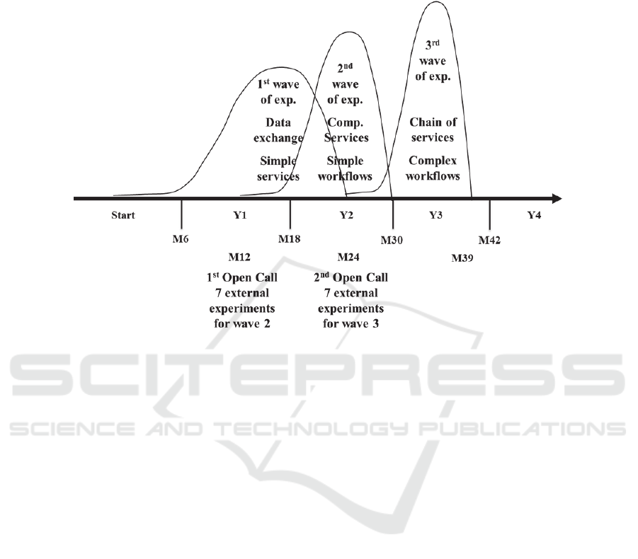
signed, see Fig. 1. The first wave of experiments is addressing the challenges of end-
user partner Stellba for the repair, maintenance and manufacture of water turbines.
Fig. 1. The three waves of experiments in CloudFlow.
The following experiments are part of the first wave:
Computer Aided Design (CAD) in the Cloud
Computer Aided Manufacturing (CAM) in the Cloud
Computational Fluid Dynamics (CFD) in the Cloud
Product Lifecycles Management (PLM) in the Cloud
Systems Simulation in the Cloud
Point clouds vs CAD in the Cloud
2 CloudFlow: System Architecture Overview
The CloudFlow Platform is built in a modular way. It consists of 5 main layers, which
may contain one or more system components. From the end user perspective all the
layers are seen as a whole but the real interactions between system components are
complex. This description ‘abstracts from’ the individual per-experiment services and
applications and focuses on the common components of the CloudFlow Platform as
presented in the following figure.
72
EPS Barcelona 2014 2014 - European Project Space on Information and Communication Systems
72
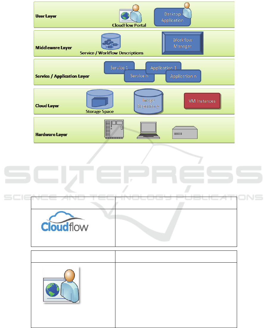
Fig. 2.The layer structure of the CloudFlow platform.
2.1 Cloudflow: Definitions
The following definitions are adapted to the CloudFlow project. The used terms may
have a slightly different or wider meaning outside of this project.
CloudFlowPlatform
The CloudFlow Platform encapsulates all of the
components illustrated in Figure 1. It comprises
everything which is required by the described
CloudFlow components to perform their tasks
and to communicate with each other.
CloudFlowPortal
The CloudFlow Portal is a web site that serves
as a user entry point to the CloudFlow infra-
structure. It is a web-based client through which
a user may log in and interact with the Cloud-
Flow system. As such, the CloudFlow Portal
provides a web-based Graphical User Interface
(GUI) that allows activating other CloudFlow
tools and applications using a standard web
browser.
73
Computational Cloud Services and Workflows for Agile Engineering
73
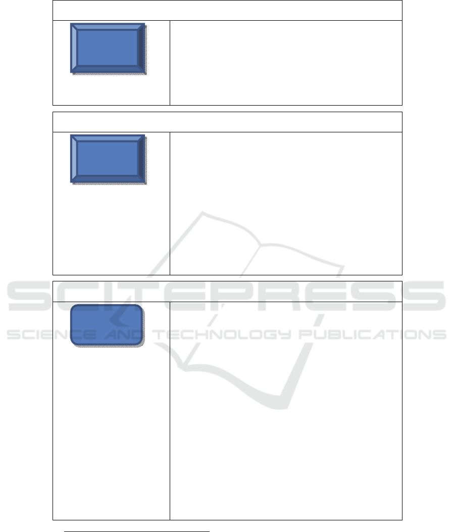
DesktopApplication
A Desktop Application is a program installed
on a user’s local machine that interacts with
the CloudFlow infrastructure. It can be used
as an alternative to the Portal.
Workflow
A workflow is a sequence of connected steps
needed to be performed to achieve a certain
work task. Every workflow step is either a
service or an application. CloudFlow work-
flows consist of one or more applications and
services. Workflows (as well as services and
applications) have semantic descriptions and
are executed by the Workflow Manager.
The main idea of this concept is to hide the
complexity of data flows and internal com-
munication from the user so that she/he can
focus on the actual engineering task.
To further ease the use of workflows, pre-
defined workflows will be created by system
administrators in collaboration with experi-
enced engineers and will be ready to use for
end users. In the future, users will also be
able to adapt pre-defined workflows depend-
ing on their individual needs using the Work-
flow Editor or to rely on an automatic as-
sembly using semantic concepts.
SemanticService/WorkflowDescriptions
The machine-readable semantic descriptions
of services, applications and workflows
comprise the respective location, functionali-
ty, inputs and outputs. This kind of service
description guarantes the compatibility be-
tween software from various vendors. The
automated checking of semantic consistency
and the inference of implicit knowledge are
only two of many advantages offered by
semantic service descriptions. In the future
development, these will be further exploited,
e.g., in the Workflow Editor.
Desktop
Application
74
EPS Barcelona 2014 2014 - European Project Space on Information and Communication Systems
74
WorkflowManager
The Workflow Manager is a CloudFlow component
that automates the execution of workflows consisting
of several services and applications and monitors their
execution status. It hides the complexity of executed
chains of services and applications by taking care of
the data flow between the inputs and outputs of the
single services and applications.
WorkflowEditor
The Workflow Editor is a CloudFlow component that
will allow users with the appropriate rights to specify
new and/or edit/change already existing workflow
definitions. The Workflow Editor backend will make
use of the semantic service and workflow descriptions
to enable a (semi-) automatic workflow crea-
tion/adaptation. It will provide a SOAP
1
interface, to
which a web-based GUI will be connected that ena-
bles comfortable access to the Workflow Editor’s
capabilities via the CloudFlow Portal. The Workflow
Editor is not yet included in the current state of devel-
opment, but will be available for future experiments.
Service
A service is a piece of software / program that runs
remotely on the Cloud performing computations.
A service provides the computation results back to
its caller. During its execution, it can, e.g., interact
with the CloudFlow Storage Space or a dedicated data
base. In CloudFlow, two types of services are distin-
guished:
a synchronous service performs its compu-
tation before returning;
an asynchronous service returns immediate-
ly and notifies the Workflow Manager using
SOAP when it is done.
Services do not rely on user input during their exe-
cution, but may display their status to the user, e.g.,
through a small web page. Services will be made
available as SOAP web services with a standardized
interface and must provide a corresponding interface
description in form of a WSDL
2
.
1
Simple Object Access Protocol
2
Web Services Description Language
Service
Workflow
Editor
Workflow
Manager
75
Computational Cloud Services and Workflows for Agile Engineering
75
Application
Applications provide a graphical interface
for the CloudFlow user to interact with a
running workflow. The purpose of applica-
tions may range from simple web pages to
let the user set parameters for the following
services or receive (intermediate) output
values to complex interactive visualization
and even remote access to commercial soft-
ware packages. Since the execution time of
an application is user-dependent and will
certainly exceed standard SOAP communi-
cation timeouts, applications use the same
mechanisms as asynchronous services to
interact with the Workflow Manager.
Storagespace
Storage Space is disc space (physical or
virtual) provided by the CloudFlow Platform
that enables to store input, intermediate, and
output data. Data from this storage space can
be downloaded to a local machine by a
CloudFlow user for archiving the data in
company data bases or additional use in
other standard applications.
VM–VirtualMachine
Virtual Machines are used to run services on
the Cloud. They contain one or more ser-
vices. To start a virtual machine, its image is
loaded from the image repository located in
the Cloud layer and executed using dedicated
virtualization software.
In order to transparently allocate on-demand
compute nodes for the execution of compute-
intensive workflows, compute-resource-
provisioning will be implemented for future
experiments. This will provide abstractions
independent from Cloud vendors for the
CloudFlow Portal and Workflow Manager in
order to bring up and shut down on-demand
instances with the correct virtual machine for
a given workflow execution.
VMInstance
Application
76
EPS Barcelona 2014 2014 - European Project Space on Information and Communication Systems
76
ImageRepository
The (virtual) Image Repository is a reposito-
ry that holds images of all VMs that are
available in the CloudFlow context. To de-
ploy a service in the Cloud, a corresponding
virtual image has to be created by the service
provider, bundling the service executable
with the needed environment. Usually, one
starts with an image provided by the Cloud
provider and installs and configure additional
software (if any). The new image is stored in
a database in the Cloud infrastructure.
Hardware
Hardware is the actual compute resource on
which services are executed. We distinguish
between Cloud hardware resources and HPC
resources.
2.2 The Interplay of the CloudFlow Components
The next illustration (Fig. 3) shows the interplay between the main software compo-
nents of the CloudFlow Platform during the execution of a workflow in a high-level
schematic way.
Fig. 3.The interaction overview of the main CloudFlow system components.
Image
Repository
77
Computational Cloud Services and Workflows for Agile Engineering
77

The Workflow Manager plays the central role of a broker to hide the complexity
of executed chains of services and applications. It allows to invoke and to monitor the
execution of services and applications, automating complex workflows that consist of
many services / applications.
The Workflow Manager is able to start a selected workflow and to pass the needed
input parameters. Then semantic descriptions of relationships between services and
applications which take part in the ordered workflow are used to pass output values
from finished services and applications to the later stages in the workflow. Asynchro-
nous services have to provide a current state of computation progress on request dur-
ing their execution. The progress status of the workflow can then be requested from
the Workflow Manager and displayed to the end user. With the same mechanism, it is
also possible for the Workflow Manager to pass the whole graphical user interface
from an asynchronous service (in this case called an application) to the end user. At
the very end of the workflow, its final results are stored by the Workflow Manager
and can later be accessed by the user upon request.
All functionality of the Workflow Manager is available through a SOAP web ser-
vice interface. It can then be accessed by user-friendly clients, as, e.g., the Portal.
Other clients, such as Desktop Applications, are also possible.
Distinct services and applications run in separate Cloud environments and thus
need the Workflow Manager as the centralized system to initiate and control the
workflows in which they are integrated. Consequently services and applications have
to implement a common interface that allows full compatibility with the Workflow
Manager and with other services and applications from various vendors. The semantic
descriptions of services, applications and workflows chosen by CloudFlow guarantee
this compatibility and let the user select workflows without the need of specific expert
knowledge for each of the services contained in a chosen workflow.
The CloudFlow software components aim at being neutral to Cloud providers and
Cloud APIs. Commonly used functionality is implemented as separate services, hid-
ing vendor specific APIs. The current implementation uses a mix of Cloud software
components. For example, the commercial software vCloud is used for controlling
virtual machines, while solutions from the open source project OpenStack are used for
authentication.
With the CloudFlow Platform, engineers as the intended main end users are given
a universal tool to configure, track and interact with expert software without any
knowledge about its implementation. To complete a certain engineering task end
users can select a suitable pre-defined workflow using the CloudFlow Portal and start
its execution. In the future, using a Workflow Editor component currently under de-
velopment, they will also have the possibility to create new workflow definitions or
adapt existing ones.
The end user is only supposed to interact with the workflow at certain points,
when its execution reaches an application. In this case, the user may for example be
asked to provide additional input of domain specific configuration information which
is not available as output from previously executed services in the workflow and can-
not be specified in advance. Applications may also display intermediate output values
or can even be interactive visualizations. Applications are implemented to run in a
browser and can thus be displayed inside the CloudFlow Portal or in Desktop Appli-
cations.
78
EPS Barcelona 2014 2014 - European Project Space on Information and Communication Systems
78

Note that the current version of the Workflow Manager only supports services us-
ing a SOAP API, where all parameters are embedded in an XML document compliant
with the respective SOAP schema. WSDL (Web Service Description Language) inter-
face descriptions are used to specify the interfaces of services and applications. The
machine-readable semantic descriptions also contain references to the information
stored in the WSDL files of the respective services and applications, as for example
their exact invocation endpoint.
3 CloudFlow: Hardware Layer
In this section we describe the current CloudFlow hardware infrastructure as provided
by Arctur (HPC partner at CloudFlow).
3.1 Cloud Configuration
Arctur uses CentOS 6 distributions of Linux in its datacenters wherever possible. If
Linux is not a possibility, then Windows Server 2008R2 or Server 2012 can be used.
Arctur's goal is to reduce manual work to a minimum; therefore most of the server
infrastructure is operated by means of the Puppet configuration management system.
VMware vCloud is used for Cloud services. On top of the actual hardware ESX
5.1 provides a hypervisor layer. In the application layer different operating systems
can be used by the consumer. Amongst the most used ones are the Ubuntu and Cen-
tOS distributions of Linux followed by Microsoft Windows Server solutions.
3.2 Hardware Configuration
Arctur’s systems to run production tasks in the Cloud can be categorized as:
hosts for virtual machines,
hosts to provide storage over iSCSI and
hosts covering infrastructure support roles.
They are generally equipped with dual core Xeon 51xx and quad core 54xx CPUs.
iSCSI runs over 1Gbit Ethernet, provided by 3com 4500G switches.
The Arctur HPC system is based on an IBM iDataPlex solution. Each of the 84
nodes is equipped with two Xeon X5650 CPUs and 32GB of memory. They are con-
nected with a high speed low latency InfiniBand network, used mainly for MPI com-
munications between nodes. This provides for 10TFlops of computing power. They
are also connected with Gbit Ethernet for management and another separate Gbit
Ethernet for the parallel file system Lustre. The Lustre system is aggregating over
100TB capacity and 4.5GB/s throughput.
Head node to the HPC cluster is an IBM machine with the same CPUs as the
compute nodes but 48GB of memory and more local storage.
One node in the system is equipped with an NVidia GPU. Due to the configura-
tion of the InfiniBand network this GPU node can be reached by every node in the
79
Computational Cloud Services and Workflows for Agile Engineering
79
HPC system, thus enabling a boost in performance if the application is able of taking
advantage of CUDA capabilities.
The HPC system/cluster is running CentOS6 with usual HPC add-ons (OFED,
MPIs, etc.). Queuing and resource management is implemented with Torque PBS +
Maui.
User applications and software are installed and configured on a pre-experiment
basis during the testing and debugging period. Therefore the software stack is con-
stantly being adapted to current demands. The software configuration is primarily left
to the actual users to configure as they need. If the configuration is needed on an ad-
ministrative level, a team of HPC system administrators supports or independently
deploys the software solutions that are needed.
4 CloudFlow: Experiments
The CloudFlow Platform, with its current infrastructure and six internal experiments,
consists of dozens of services and applications. In this section there is a brief explana-
tion of each of the initial experiments.
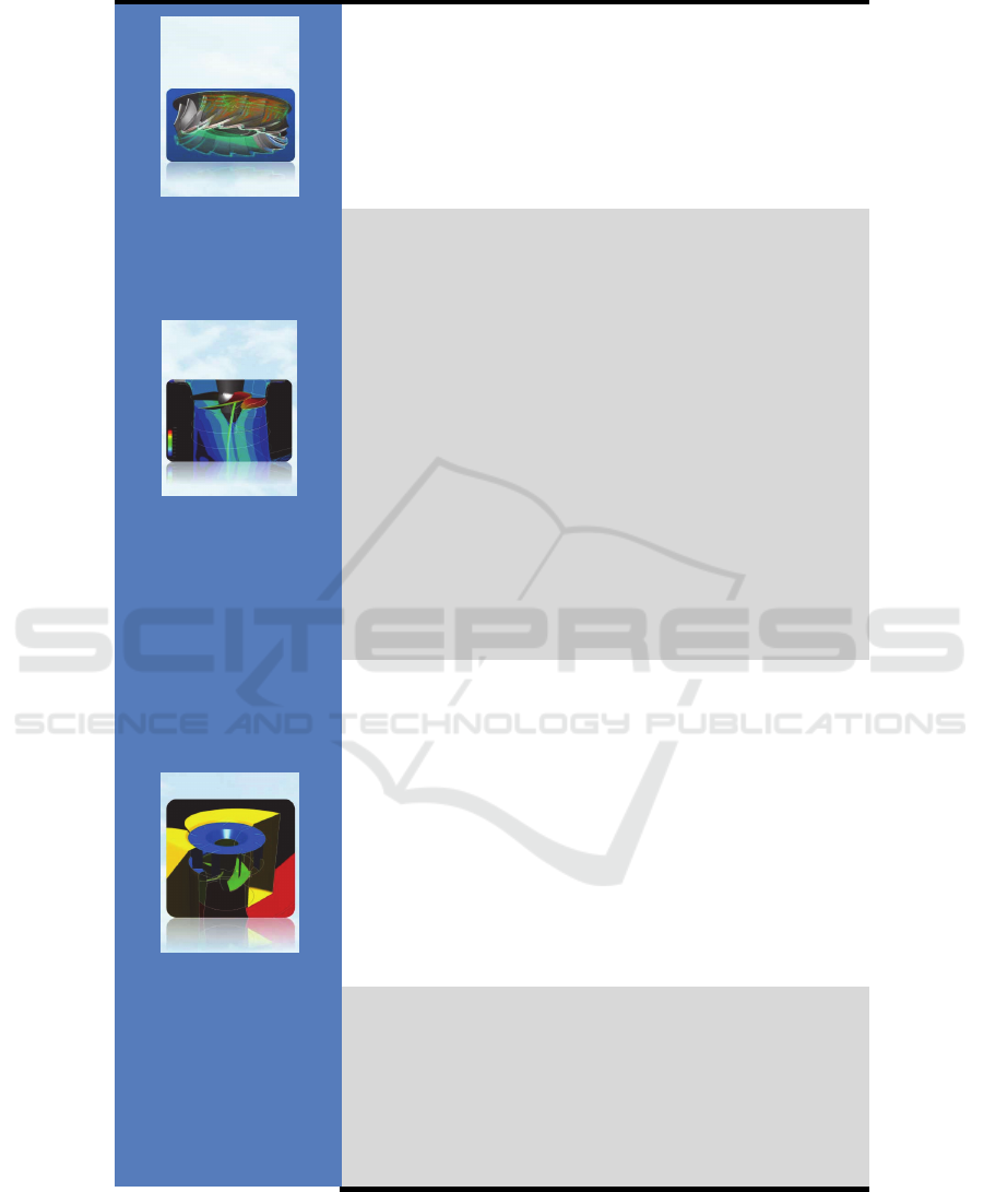
Experiment Summary
1. Computer Aided
Design (CAD) in the
Cloud
Parametric design of products in CAD has enabled the
industry to parameterize classes of their product shapes
thus significantly increasing productivity. However,
standard parametric design functionality in CAD systems
does not cover all product classes well. This is especially
true for products with a sculptured shape. For such prod-
ucts tailored design applications are often the way to go,
however, these are in general expensive as their market is
small, and distribution through traditional vendors lim-
ited. Supporting such systems on a big spectrum of
hardware platforms is prohibitive. On the other hand,
selling services for parametric CAD in the Cloud will
remove the complexity of traditional distribution and
focus the support only on the hardware of the Cloud
platforms used.
2. Computer Aided
Manufacturing
(CAM) in the Cloud
Although commercial CAM software offers a wide spec-
trum of functionality, some companies have specific
machines, processes and requirements that are not cov-
ered by standard solutions. To solve these challenges
either expensive niche software has to be purchased or
company specific CAM technology has to be developed.
The Cloud allows services to be offered on the global
market targeting niche CAM needs. CAM-based assem-
blies are always specific and are designed on demand.
The assembly depends on a CAM type (cylindrical, glo-
80
EPS Barcelona 2014 2014 - European Project Space on Information and Communication Systems
80
bic, and planar), a set of parameters, and one or more
movement laws. The result will be the ISO file for ma-
chining the part to be produced according to the customer
machine (Post Processing).
3. Computational
Fluid Dynamics
(CFD) in the Cloud
The proposed workflow starts from the initial and re-
leased CAD representation of a 3D geometry. The mesh
generation service will be used to generate the mesh,
which will then be input to the CFD solver running on
the Cloud, possibly on a different infrastructure. The
mesh generation and solver service on the Cloud run in a
transparent way for the user. The process will in many
cases need to be run iteratively to reach the optimal de-
sign. For this experiment, the meshing setup and CFD
setup are carried out on the user’s local machine. The
monitoring of the solver convergence will be through a
web interface, either through a dedicated thin client or
through a web browser. In this experiment, small and
medium sized problems are tackled. CAD input files will
typically range for a few megabytes to tens of mega-
bytes. Meshes and CFD results are expected to range
from tens to hundreds of megabytes.
4. Product Lifecycles
Management (PLM)
in the Cloud
The experiment will implement the PLM support of a
basic analysis process: design, mesh generation, loads
definition, analysis and post-processing. These steps
produce several 3D-models of the analyzed product: the
CAD model, the meshed model and simulation result
models for various load cases. This experiment will focus
on giving the user easy, fast and useful access to these
graphical models for visual inspection.
Visual inspection is given priority in this experiment as
one of the most efficient methods of verification and
validation.
5. Systems Simula-
tion in the Cloud
The experiment will implement CloudFlow services that
allow to define and execute systems simulation tasks and
to analyse the simulation results.
The simulation model describes an electro-hydraulic
power plant, including surge tank, distributed pipe with
right distribution of pressures and a simple curve-based
model of a Kaplan or Francis hydraulic turbine. This
81
Computational Cloud Services and Workflows for Agile Engineering
81

system model is usable for pre-dimensioning of compo-
nents and the test of critical use scenarios as for example
full load-shutdown to avoid water-hammer effects. These
cases need time-consuming parameter variations due to
the performance-disturbing distributed pipe. Additional-
ly system models are used for the examination of rarely
occurring cases of damage (e.g. extreme use situations
such as low temperatures).
The result of this experiment will be a service interface
which is independent from a systems simulation tool
vendor. The implementation with SimulationX provides
the proof of concept.
6. Point clouds vs
CAD in the Cloud
The power efficiency of water turbines is strongly related
to the shape of their blades. The CAD-model and the
models used for calculating the power efficiency do not
exactly represent the blade shapes produced. A turbine
and its blade last decades. During their lifetime the blade
shape is worn by silt and sand. Under some circumstanc-
es cavitation can severely damage the blade surface. The
application experiment thus serves two purposes:
Comparing the produced turbine blades with
their nominal shape (CAD-shape).
Checking older turbines and their blades for
wear and deciding on the need for repairs and
upgrades.
5 CloudFlow: Business Aspects
In addition to the potential business models for each of the software vendors Cloud-
Flow has analysed possible concepts to be validated for the CloudFlow Platform as a
common aggregator of solutions operated by the HPC organisation.
5.1 Value Proposition
Product name
CloudFlow Engineering Software Platform.
Most Relevant Technical Characteristics
CloudFlow Platform is the aggregation portal of all software applications being part
of the CloudFlow project. It will be automated to the point that the customer can easi-
ly and seamlessly work with the different software tools.
82
EPS Barcelona 2014 2014 - European Project Space on Information and Communication Systems
82

Differential Aspects in Front of Most Important Competitors
CloudFlow is workflow-based. The differential and unique value of CloudFlow in
front of competitors is based on the workflow approach to the use of the different
applications. It is not just the aggregation of software tools or a simple marketplace, it
is the seamless and transparent combination of interoperable services.
5.2 Distribution
Distribution Channels
The distribution of the platform should be done combining the natural and fundamen-
tal Internet approach together with the expert support of the software vendors. This
two-fold method should add a synergistic effect for the customer.
Marketing
Marketing should be covered addressing 4 topics: (1) Internet marketing, (2) SEO -
Search Engine Optimization-, (3) Specialised Media and (4) traditional marketing
from software vendors.
5.3 Customer Relationship
The workflow management should be as automatic as possible thus facilitating the
independent operation of the CloudFlow platform. In any case, the platform should
give customers the option to get in touch with experts by means of a hot-line or any
analogous mechanism. Therefore, CloudFlow should have easily accessible experts
for each software tool, but also for the HPC and cloud infrastructure and for the work-
flow process management itself.
5.4 Customers
The target customers of the platform should be the same of the detected customers for
the individual software tools. On top of that, sectors and industries making intensive
use of workflows combining different services within CloudFlow should be identi-
fied.
5.5 Revenue Streams
Incomes
In front of the customer, CloudFlow should be seen not only as a single entry point to
all services or just as a marketplace. On the contrary, CloudFlow should be perceived
as a unified common system with a centralised payment procedure. The customer
should clearly know what he gets in return for the money he is about to pay. We can
compare and study in detail three payment methods: (1) Prepaid model, (2) Actual
usage fee and (3) Subscription fee. This is the transparent approach to the customer,
behind the unified payment system the shareholders of the platform should internally
83
Computational Cloud Services and Workflows for Agile Engineering
83

distribute the money following a common approved pattern.
The prices may vary depending on the frequency/loyalty of each customer and/or the
number of services to be operated.
Incomes depend on: (1) Software application, (2) Computing power, (3) Storage re-
sources. In addition to this transparent part, the user should also be charged for (4)
Portal use, (5) Internet communications if there is any singular demand on that issue.
5.6 Key Resources
Personnel
The key resources in the CloudFlow Platform case are:
Software applications, HPC and Storage resources. They are the key services
within the CloudFlow Platform.
Portal and Internet. It is the basic distribution channel for the cloud services.
Communication. It is sometimes a critical factor (private channels, direct
links, special services).
Supporting personnel. System and portal support, and experts assisting cus-
tomers online.
5.7 Key Activities
Portal operation and administration. Including charging, billing and internal
distribution of funds.
Security.
Supporting services. Including experts from all domains (software, HPC,
workflows...).
Software upgrading.
Marketing, commercialisation and exploitation.
5.8 Key Alliances
Key alliances should cover on the one hand the basic commercial relationship be-
tween the software providers and the HPC provider. In addition to that, the organisa-
tion in charge of exploiting the Portal should be a key ally, as well as the telecommu-
nication provider.
In CloudFlow the HPC provider and the Portal administrator is the same organisation.
5.9 Cost Structure
The main costs involved in the operation of our CloudFlow Platform are those related
to:
84
EPS Barcelona 2014 2014 - European Project Space on Information and Communication Systems
84

Hosting. Including renting space.
Operating costs. Internet communications, electricity, system support, portal
support, services support.
Upgrading costs.
6 Conclusions
Traditionally, the European manufacturing industry is characterized by innovative
technology, quality processes and robust products which have leveraged Europe’s
industrialization. However, globalization has exposed Europe’s industry to new
emerging and industrialized manufacturing markets and the current economic chal-
lenges have decelerated the internal boost and investment, respectively. Hence, new
ICT infrastructures across Europe need to be established to re-enforce global competi-
tiveness.
CloudFlow has the ambition to provide a Cloud Computing infrastructure based
on existing technology and standards that allows SME software vendors to offer cur-
rent and future customers (being it SME or bigger companies) new cloud services
along and across the engineering and manufacturing chain - even vendor independent.
CloudFlow covers Computer Aided Design and Manufacturing (CAD/CAM),
Computer Aided Engineering (CAE), Computational Fluid Dynamics (CFD) includ-
ing pre- and post-processing, simulation of mechatronic systems (Functional Digital
Mock-Up – FDMU) and Product Lifecycle Management (PLM) including data ar-
chival.
CloudFlow will enable Users from different engineering disciplines to manage
large amounts of heterogeneous Data in an interoperable manner, allowing for making
results available as a standard Archival Information Package (AIP) both for documen-
tation and for reuse. CloudFlow will provide ‘single point of access’ to computational
(simulation) and data management Services on high-performance clusters (HPCs) and
the possibility to use services in Workflows, i.e. execution of chains for services or
services-in-a-loop in a synchronized and orchestrated manner, as well as to use ser-
vices in a cooperative and collaborative manner, e.g. for co-simulating mechatronic
systems, for joining up CAD/CAM with flow simulation of blades for turbine ma-
chines. Thus, it does decisively go beyond just providing individual data exchange or
singular compute services.
CloudFlow will establish a Competence Center from the very beginning to call for
Application Experiments to handle proposals by the CAD/CAM, CAE, Systems and
PLM community and their execution on the CloudFlow infrastructure. There will be
three waves of experiments, the first wave starting in the first phase of the project
with experiments from the core partners is already in place. The second and third
waves will be open to the community and will call for increasingly complex and chal-
lenging use cases, especially on engineering and manufacturing services and work-
flows.
The whole CloudFlow system is built in a multilayer architecture to separate func-
tionalities. It consists of 5 main layers, which may contain one or more system com-
85
Computational Cloud Services and Workflows for Agile Engineering
85

ponents. From the end user perspective all the layers are seen as a whole but the real
interactions between system components are complex.
At the very top in the system’s hierarchy there is the User Layer. Its main task is
to provide an entry point for the user of the CloudFlow system. It contains the Cloud-
Flow Portal and desktop applications (adjusted to cooperate with the CloudFlow in-
frastructure) that enable users to choose, configure and control the execution of work-
flows. They also give the possibility to interact with applications when it is necessary.
To enable the seamless integration of services and applications from different
software vendors, the Workflow Management Layer was designed. This layer con-
tains applications and storage space to automate the management and maintenance of
the user’s workflows.
The Service / Application Layer is the most important part of the system from the
end user’s view. It provides expert software that can be used by the end user. This
software is divided into separate services and applications, which offer different func-
tionalities and can be efficiently connected into workflows to suit individual custom-
er’s needs.
In between the Service / Application Layer and the Hardware Layer, the Cloud
Layer is implemented. Its role is to enable scalable access to the hardware resources.
It provides access to the storage space, where all the user and temporary file can be
stored, a repository with images of Virtual Machines (VM) and the VM instances, in
which the three uppermost CloudFlow layers run.
The whole CloudFlow system uses the hardware infrastructure provided by Arc-
tur. Its cluster structure enables to assign the hardware resources in a very flexible
way, depending on the actual needs.
The infrastructure will be expanded and improved in the next project phases as
CloudFlow will conduct two Open Calls for external experiments investigating the
use of the CloudFlow infrastructure in new and innovative ways, outreaching into the
engineering and manufacturing community and engaging external partners. Each of
these two Open Calls will look for seven additional experiments to gather experience
with engineering Cloud uses and gaining insights from these experiments.
CloudFlow is striving for the following impacts: a) increasing industrial competi-
tiveness by contributing to improve performance (front-loading, early error detection,
time-to-market, …) and innovation (co-use of models, early virtual testing), and b)
improving in innovation capabilities by enabling more engineers to gain insights and
to create innovation by accessing ‘new’ tools and easing the use of Cloud Infrastruc-
tures.
References
1. CloudFlow project www.eu-cloudflow.eu
2. Deliverable D800.10 V1 of CloudFlow infrastructure: Part 1. Experiments; Part 2. Infra-
structure; Part 3. Business aspects.
3. Qi Zhang, Lu Cheng and Raouf Boutaba: Cloud Computing: State-of-the-Art and Research
Challenges. Journal of Internet Services and Applications (JISA), 2010 http://www.cs.
uwaterloo.ca/~rboutaba/Papers/Journals/2010/Qi10.pdf
86
EPS Barcelona 2014 2014 - European Project Space on Information and Communication Systems
86

4. Schubert, L.; Jeffery, K. (Ed.); Neidecker-Lutz, B. (Ed.): The Future of Cloud Computing
Opportunities for European Cloud Computing Beyond 2010. Expert Group Report, Public
version 1.0, http://cordis.europa.eu/fp7/ict/ssai/docs/cloud-report-final.pdf
5. Schubert, L.; Jeffery, K. (Ed.): Advances in Clouds. Expert Group Report, Public version
1.0, 2012.
6. Gruber, T.R. A translation approach to portable ontology specifications. Knowl. Acquis.
1993, 5, 199–220.
7. Smith, M.K.; Welty, C.; McGuinness, D.L. OWL Web Ontology Language Guide; World
Wide Web (W3C): Cambridge, MA, USA, 2004.
8. Manola, F.; Miller, E. RDF Primer; W3C Recommendation; World Wide Web (W3C):
Cambridge, MA, USA, 2004.
9. Stork, A.; Gorecky, D.; Stahl, C.; Loskyll, M.; Michel, F.; Sevilmis, N.; Weber, D. Ena-
bling Virtual Assembly Training in and beyond the Automotive Industry. In: Conference
Proceedings. 18th International Conference on Virtual Systems and MultiMedia (VSMM-
2012), IEEE, September 2-5, Milan, Italy, 2012.
10. Bhiri, S.; Gaaloul, W. Semantic web services for satisfying SOA requirements. Adv. Web
Semant. I 2009, 4891, 374–395.
11. Kopecký, J.; Vitvar, T. Sawsdl: Semantic annotations for WSDL and XML schema. IEEE
Internet Comput. 2007, 11, 60–67.
12. Roman, D.; Keller, U.; Lausen, H. Web service modeling ontology. Appl. Ontol. 2005, 1,
77–106.
13. Martin, D.; Burstein, M. Bringing semantics to web services with OWL-S. World Wide
Web 2007, 10, 243–277.
14. http://cloudfoundry.org/
15. Dyken E.C., et.al., "A Framework for OpenGL Client-Server Rendering". 4th International
Conference on Cloud Computing Technology and Science, IEEE, 2012.
16. Limmer, S.; Schneider, A.; Boehme, C.; Fey, D.; Schmitz, S.; Graupner, A.; Sülzle, M.:
Services for Numerical Simulations and Optimizations in Grids. The 2nd IEEE Internation-
al Conference on Parallel, Distributed and Grid Computing. Waknaghat, India, December
6- 8, 2012.
17. Dean, J.; Ghemawat, S.: MapReduce: Simplified Data Processing on Large Clusters. Sixth
Symposium on Operating Systems Design and Implementation (OSDI '04), San Francisco,
California, USA, December 6-8, 2004.
18. Cloud Standards: http://cloud-standards.org
19. J. M. Noguera, R. J. Segura, C. J. Og´ayar, and R. Joan-Arinyo, “Navigating large terrains
using commodity mobile devices,” Computers and Geosciences, vol. 37, no. 9, pp. 1218 –
1233, 2011.
20. “Paraviewweb website,” http://paraviewweb.kitware.com/PW/, accessed August 2012.
21. F. Niebling, A. Kopecki, and M. Becker, “Collaborative steering and post-processing of
simulations on hpc resources: everyone, anytime, anywhere,” in Proceedings of the 15th In-
ternational Conference on Web 3D Technology, ser. Web3D ’10. New York, NY, USA:
ACM, 2010, pp. 101–108.
22. M. Anttonen, A. Salminen, T. Mikkonen, and A. Taivalsaari, “Transforming the web into a
real application platform: new technologies, emerging trends and missing pieces,” in Pro-
ceedings of the 2011 ACM Symposium on Applied Computing, ser. SAC ’11. New York,
NY, USA: ACM, 2011, pp. 800–807.
23. C. Mouton, K. Sons, and I. Grimstead, “Collaborative visualization: current systems and
future trends,” in Proceedings of the 16th International Conference on 3D Web Technolo-
gy, ser. Web3D ’11. New York, NY, USA: ACM, 2011, pp. 101–110.
24. CimData May 2010, http://www.cimdata.com/
25. ISO 10303-209, Industrial automation systems and integration — Product data representa-
tion and exchange — Part 209: Application protocol: Multidisciplinary Analysis and De-
sign.
87
Computational Cloud Services and Workflows for Agile Engineering
87

26. Functional Mock-up Interface (FMI): https://www.fmi-standard.org
27. Enge-Rosenblatt, O.; Clauß, C.; Schneider, A.; Schneider, P.: Functional Digital Mock-up
and the Functional Mock-up Interface – Two Complementary Approaches for a Compre-
hensive Investigation of Heterogeneous Systems. Proceedings of the 8th International Mod-
elica Conference, March 20th-22nd, Dresden, Germany, pp. 748-755
88
EPS Barcelona 2014 2014 - European Project Space on Information and Communication Systems
88
