
On Combining the Dielectrophoresis and Microdevices
Investigation of Hippocampal Neuronal Viability after Implementing
Dielectrophoretic Positioning on Multi-Electrode Arrays
Tianyi Zhou
1
, Susan F. Perry
2,3
and Svetlana Tatic-Lucic
1,3
1
Department of Electrical and Computer Engineering, Lehigh University, Bethlehem, PA 18015, U.S.A.
2
Department of Chemical Engineering, Lehigh University, Bethlehem, PA 18015, U.S.A.
3
Bioengineering Program, Lehigh University, Bethlehem, PA 18015, U.S.A.
Keywords: Viability, Hippocampal Neurons, Multi-Electrode Array (MEA), Dielectrophoresis (DEP), Sucrose,
Membrane Potential.
Abstract: In this work, we have investigated the viability of embryonic mouse hippocampal neurons after
dielectrophoretic positioning on multi-electrode arrays (MEA). We present a systematic evaluation of
positive dielectrophoretic conditions, including 1) an investigation of the effect of 10% sucrose (w/v in
deionized water), a commonly used, low-conductivity buffer medium, on the viability of mouse
hippocampal neurons over different time periods, and 2) a study of the effect of the membrane potential
induced by DEP electric field on the integrity of the cell membrane. Post-DEP high neuronal viability was
achieved experimentally, and spontaneous neuronal potentials from trapped neurons on the MEA were
successfully recorded.
1 INTRODUCTION
Microsystems based on dielectrophoresis (DEP),
being flexible and label-free, have been widely used
to position, separate, and characterize particles and
biological cells (Gagnon, 2011; Li et al., 2014;
Pethig, 2010). For instance, various types of cells,
such as rat hippocampal neurons (Honegger et al.,
2013) and human liver cells and endothelial cells
(Ho et al., 2013) have been successfully manipulated
and patterned by DEP, while circulating tumor cells
(CTC) have been isolated from blood cells using
microdevices integrating DEP and microfluidics
(Gupta et al., 2012). Likewise, neuronal stem cells,
neurons and glial cells have been characterized and
separated with DEP microsystems (Prieto et al.,
2012).
On the other hand, extracellular multi-electrode
arrays (MEAs) have provided reliable platforms for
neuronal potential recording because of their non-
invasive nature (Berdondini et al., 2009; Hochberg
et al., 2006; Spira and Hai, 2013). These MEAs
facilitate the study of neuronal physiology and
communication through simultaneous in vitro
recordings and stimulations from multiple neurons.
By increasing the number of electrodes,
conventional MEAs have been widely used for
tissue-level or high-density neural culture and
recording (Berdondini et al., 2009; Stevenson and
Kording, 2011; Viventi et al., 2011).
Incorporating DEP on MEAs, as demonstrated
by the work of Jaber et al., 2009, Rozitsky et al.,
2013, and Yoshimura et al., 2014, enables a
microsystem to efficiently position individual
neurons on single electrodes, as well as to precisely
track and investigate electric signals from specific
individual neurons. According to Pohl 1978, the
polarization of a dielectric particle (e.g. a neuron),
when exposed to a non-uniform electric field, drives
the cell towards the maximum or minimum of
electric field, depending on the relative dielectric
and conductive properties of the cell and the
suspension medium. Positive dielectrophoresis
(pDEP) actively traps cells to the electrodes
(maximum of electric field), while negative
dielectrophoresis (nDEP) pushes cells away from
these areas.
In order to pattern neurons with positive
dielectrophoresis (pDEP), neurons have to survive
the implementation of pDEP, which attracts them to
the electrodes. Two factors influence the viability of
71
Zhou T., Perry S. and Tatic-Lucic S..
On Combining the Dielectrophoresis and Microdevices - Investigation of Hippocampal Neuronal Viability after Implementing Dielectrophoretic Positioning
on Multi-Electrode Arrays.
DOI: 10.5220/0005180200710077
In Proceedings of the International Conference on Biomedical Electronics and Devices (BIODEVICES-2015), pages 71-77
ISBN: 978-989-758-071-0
Copyright
c
2015 SCITEPRESS (Science and Technology Publications, Lda.)

neurons during the application of pDEP: 1) the DEP
cell-trapping solution, because its low conductivity,
which is desirable for trapping (pDEP is not possible
in high conductivity, standard culture media), is not
optimal for cell survival, and 2) electric field. The
viability of a few types of neural cells, such as
neural cortical cells and neural stem/progenitor cells
(NSPCs), in DEP manipulation was investigated
previously (Heida et al., 2001; Lu et al., 2012), and
high cell viability was achieved for short-term (1
min or less) DEP exposure. In this work, we
systematically evaluate the long-term (up to 12
hours) viability of embryonic mouse hippocampal
neurons after being actively positioned on the
electrodes of a custom-made MEA using
dielectrophoresis.
2 MATERIALS AND METHODS
2.1 Experimental Setup for the Study
of the Hippocampal Viability in
Sucrose
In order for pDEP to take effect, the polarization of
neurons should be stronger than that of surrounding
media (Jones, 1995), which requires a low-
conductivity environment. As a commonly used,
low-conductivity buffer medium, sucrose solution is
often used as the primary component of a pDEP
trapping solution (Huang et al., 2014; Pethig, 2010;
Vahey and Voldman, 2009). In our experiments, a
30% cell media DEP suspension medium, which is a
mixture of seven parts of 10% sucrose(w/v in
deionized water) and three parts of primary neuron
culture media, NbActiv1 (BrainBits, LLC.), is used
for neuronal pDEP recruiting on MEA. This
sucrose/cell media mixture, with a measured
conductivity of 0.331 S/m, has low conductivity and
appropriate physiological osmolarity for neurons to
survive (Jeng et al., 2010) during pDEP trapping.
While cell culture media does not compromise
the health of neurons, the viability of embryonic
mouse hippocampal neurons, in 10% sucrose, which
is the major component of the cell-trapping solution,
was investigated. Dissociated hippocampal cells
were resuspended in three sterile 15 mL centrifuge
tubes, each containing 5 mL 10% sucrose (w/v in
deionized water), and in another centrifuge tube of 5
mL cell media NbActiv1 as a control group. The
three sucrose samples were placed at room
temperature (RT) for 30, 60 and 90 min respectively,
and the control tube was placed at RT for 90 min.
After each associated time period, 5 mL of
phosphate buffered saline (PBS) was added to each
of the sucrose tubes, and the samples were
centrifuged at 200g for 5 min to harvest the cells.
We found the dilution with PBS, above, necessary
for pelleting the cells, because otherwise cells
remained suspended in the high-viscosity sucrose
solution, even after being centrifuged. The viability
of harvested cells was assessed through use of
Live/Dead
TM
cell stain, (Invitrogen; Calcein, AM
2M and Ethdium Homodimer, 1M in cell media
NbActiv1). After 15 min in dark at RT, the cell
suspension was transferred to a 35 mm petri dish
using a micropipette, and five live/dead fluorescent
micrographs were taken at random positions, for
each sample, including the control group. Percent
cell viability was calculated based on the average of
five images. Typically, 30-40 cells were counted on
each of the image.
2.2 Simulation and Modeling of the
Effect of MEA Electric Field on
Hippocampal Viability
Membrane breakdown, or electroporation, is the
process where a biological cell membrane is turned
into a high-conductivity state because of a
membrane potential induced by an external electric
field (Heida et al., 2002). This process comes with
the creation of pores on the membrane. When
induced membrane potential exceeds the threshold
level, expansion of membrane pores or creation of
more pores leads to membrane breakdown, which
can be a fatal effect while trying to attract
hippocampal neurons to electrodes using pDEP.
According to Zimmermann and Neil, 1996, in an
AC electric field E, the generated membrane
potential is given by:
1.5
12
(1)
with the static electric field, r the cell radius, α the
angle between the electric field line and a vector
from the cell center to an associated point on the
membrane, f the electric field frequency, and τ the
time constant of cell membrane expressed as (Heida
et al., 2002):
1
1
2
(2)
where
is the effective cell membrane capacitance
per unit area, and
and
are the conductivities of
cell interior (cytoplasm) and surrounding medium,
respectively.
BIODEVICES2015-InternationalConferenceonBiomedicalElectronicsandDevices
72
From equation (1), the induced membrane
potential is frequency-dependent. Furthermore, the
maximum potential is at the membrane point facing
an electrode (assuming the cell sitting on top of a
planar electrode), where the electric field line is
parallel to the vector from cell center to the
membrane point, giving =1 or =-1. The
manipulation of cells using DEP requires a non-
uniform global electric field, as mentioned above.
However, if the local electric field is assumed to be
uniform and static (constant ), the induced
membrane potential can be calculated based on the
protoplast (single-shell) model of a mammalian cell
(Jones, 1995; Zhou and Tatic-Lucic, 2012). In this
model, the mammalian cell is represented by a
homogeneous cell interior (cytoplasm) with ohmic
conductivity
, and a thin capacitive cell membrane
layer with effective capacitance
.
2.3 Post-DEP Hippocampal Viability
Verification
The viability of pDEP recruited hippocampal
neurons on the MEA was verified, using the same
Live/Dead
TM
cell stain, as described above. Primary
neuron culture media NbActiv1, which was the
media neurons incubated in after the DEP
positioning, was replaced carefully by the live/dead
stain with a micropipette. The sample was placed in
dark at RT for 15 min, and visualized immediately
with a Nikon ECLIPSE E800 upright fluorescent
microscope.
3 RESULTS AND DISCUSSION
3.1 Hippocampal Viability in Sucrose
The main objective of our study was to evaluate the
effect of the cell-trapping solution on the viability of
embryonic mouse hippocampal cells. Cells were
exposed to 10% sucrose for various periods of time
(30, 60 and 90 min) and their viability analyzed, as
previously described in Section 2.1. Since the cell
media component of the trapping solution does not
compromise the health of cells, their viability was
investigated in a more severe (10% sucrose, only)
situation.
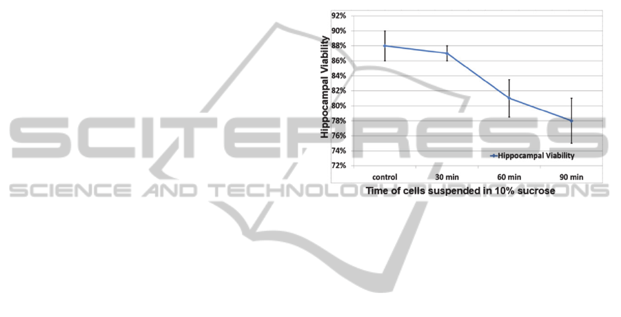
As shown in Figure 1, all three sucrose treatment
samples had acceptable hippocampal viability
compared to the control group (cell media); the
parameter that should be kept in mind is that the
entire pDEP trapping process normally lasts for less
than 30 min, thus, that is the duration of exposure to
cell trapping solution that has relevance for most of
the experimental setups. The viability decreases
slightly from 88±2% to 78±3%, as time in sucrose
increases (up to 90 min), but the detrimental effect
on cell survival is limited, confirming the feasibility
of using 10% sucrose as the major component of the
cell-trapping solution. In Figure 1, the error bars
represent the standard deviations of data from five
randomly-taken images.
Figure 1: Hippocampal viability assessment after sucrose
treatments for various periods of time.
3.2 Neuronal Membrane Potential
Simulations on MEA
Another facet of this viability study is the
investigation of the induced cell membrane potential
resulting from non-uniform DEP electric field,
which, if it exceeds certain threshold value, could
compromise neuronal health; this threshold value is
known as the breakdown potential (Heida et al.,
2002; Huang et al., 2014). Detailed simulations
were performed to ensure cell membrane integrity
with the application of a 6 Vpp, 10 MHz AC signal.
This signal was selected based on our prior studies
on the DEP parameters that secure the attraction of
neurons, only, on the electrodes, as opposed to glial
cells which are also present in the cell medium
(Zhou et al., 2014).
In order to explore the intricacies of pDEP
attraction of cells on electrodes, DEP electric field
simulation was performed with CoventorWare
(Coventor, Inc.) finite element analysis (FEA)
software (Zhou and Tatic-Lucic, 2012). A simplified
one-electrode model based on targeted device
structure was built (see Figure 2(a)). In this model, a
single electrode is sandwiched between glass
substrate and silicon oxide passivation layer, and a
via is etched through the passivation layer to open
and define the electrode site. SU-8 epoxy is patterned
OnCombiningtheDielectrophoresisandMicrodevices-InvestigationofHippocampalNeuronalViabilityafter
ImplementingDielectrophoreticPositioningonMulti-ElectrodeArrays
73
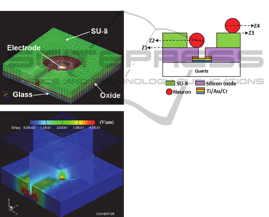
above the passivation layer, where different
microstructures, including microchambers and
microtrenches, are created using photolithography. In
the electrostatic simulation, +3V potential was
applied to the electrode. The simulated electric field
distribution is shown in Figure 2(b). It can be seen
that the electric field maximum area is located above
the open via, as the central red peak extending above
the surface indicates. This means the cell will be
attracted to the open via on top of the electrode when
pDEP is implemented (Zhou and Tatic-Lucic, 2012).
(a)
(b)
Figure 2: (a) FEA model of DEP MEA electrode structure.
(b) Simulated electric field distribution using Coventor.
From this electrode finite element analysis
modeling, 2-D electric field data on four different
planes of interest was extracted, as shown in Figure
3. These four planes are representative surfaces
where hippocampal neurons experience induced
membrane potential during pDEP anchoring. The
first plane (Z1) is the surface of the silicon oxide
passivation layer; the second plane (Z2) is the level
of the neuron’s center when the neuron lands on the
silicon oxide layer; the third plane (Z3) is the surface
of the SU-8 layer; and the last plane (Z4) is at the
level of the center of the neuron when the neuron is
positioned on top of the SU-8 layer. Z1 and Z2 are
established when the cell has been trapped on an
electrode; Z3 and Z4 represent the cell floating on
device surface just before anchored to the electrode
by DEP. The position and distance between each
plane are based on dimensions obtained from a
fabricated DEP MEA and from the measured radii of
hippocampal neurons (r= 4 m).
Figure 3: Four planes (Z1-Z4) where electric field data
was extracted and induced neuron membrane potential
was calculated.
As mentioned earlier, the simulated maximum
electric field is above the electrode, which is also the
center point of each 2-D plane extracted. Using this
electric field maxima and related hippocampal
neuronal dielectric properties (Chitwood et al., 1999;
Gentet et al., 2000; Heida et al., 2001; Major et al.,
1994), the frequency dependence of maximum
(=1) induced membrane potential
on four
planes was calculated in Matlab (MathWorks, Inc.).
In Figure 4, two graphs indicate the situation where
the voltages of 3 V and 4 V were applied to the
electrode, respectively.
As can be seen in Figure 4, the induced
membrane potential is greater on lower planes
(greater electric field strength); nevertheless, the
potential on each plane decreases as frequency
increases. With different electrode configurations
and DEP conditions, Huang et al., 2014 and
LaLonde et al., 2014 reported similar results. It was
reported that an induced membrane potential below
0.4 V can probably guarantee the survival of cortical
neurons, and larger membrane potentials can be
tolerated by cortical cells at higher frequencies
(Heida et al., 2001; Heida et al., 2002). Assuming
0.4 V is also the membrane breakdown threshold for
hippocampal neurons, the membrane potentials are
BIODEVICES2015-InternationalConferenceonBiomedicalElectronicsandDevices
74
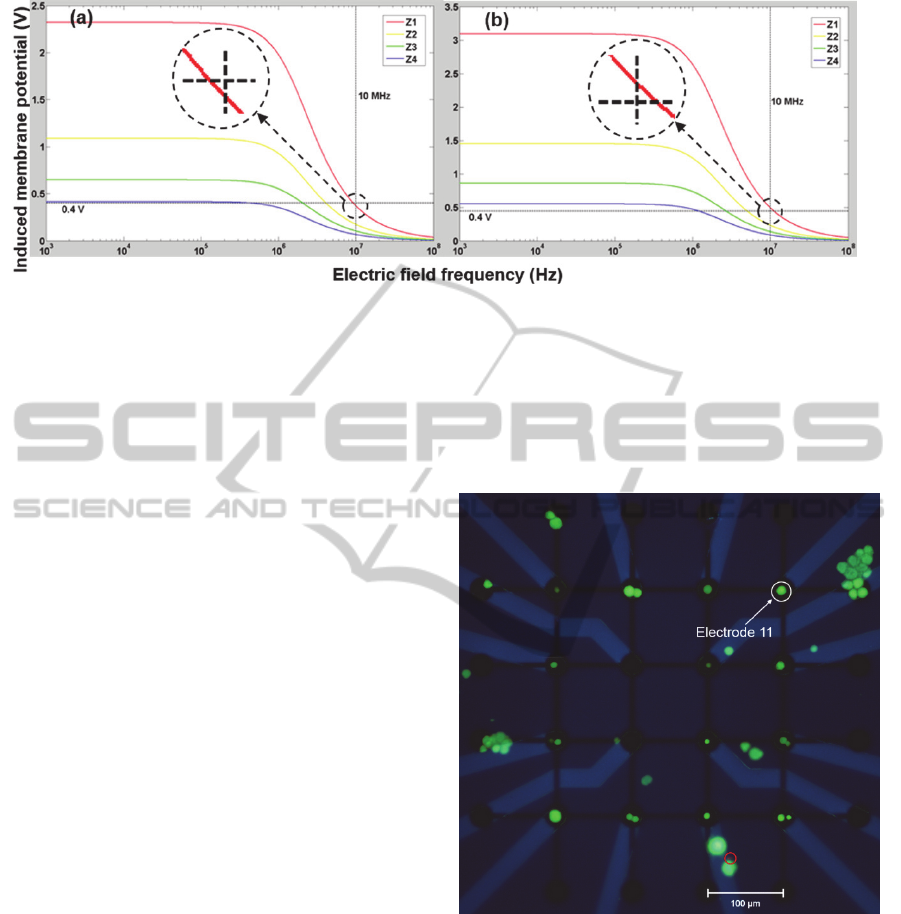
Figure 4: Calculated hippocampal membrane potentials induced by external electric field when (a) 3 V and (b) 4 V is
applied on the bottom electrode. Two close-up views for potentials on Z1 at 10 MHz are provided, compared with the 0.4 V
threshold.
all below this level at 10 MHz when 3 V is applied,
as indicated by the close-up view in Figure 4(a).
However, the potential is still above 0.4 V on plane
Z1 if 4 V is applied at 10 MHz, which could lead to
cell death when the neuron is anchored on top of the
electrode. For this reason, 6 Vpp (-3 V to 3 V), 10
MHz AC signal was used for hippocampal neuronal
recruiting on the MEA.
It should be mentioned, however, that this
membrane potential is not the only factor impacting
the viability of hippocampal neurons. For instance,
some neurons may have already died during the
dissociation process, even before they are exposed to
the electric field (Heida et al., 2001). Therefore,
approaches to simultaneously track the change of
neuronal membrane potential and verify the
membrane breakdown-associated cell death are in
need, as such necrosis directly relates to external
electric field during pDEP implementation.
3.3 Hippocampal Viability Verification
and Neuronal Potential Recording
The next step in our work was to experimentally
verify the viability of the neurons that were attracted
to MEA electrodes and positioned there by pDEP.
We used the DEP AC signal of 6 Vpp and 10 MHz,
and implemented live/dead staining process to
determine whether neurons survived the recruiting
procedure. Live/dead staining, which requires media
change and manual manipulation, as described in
Section 2.3, was not possible immediately following
the application of pDEP, because newly placed cells
were easily displaced. Therefore, staining was
performed 12 hours post-pDEP, for neurons to better
attach on the electrode. As can be seen in Figure 5,
after 12 hours in vitro, pDEP positioned
hippocampal neurons on MEA have better than 96%
viability (96±2%, n = 7), verifying the integrity of
the cell membrane and that neurons stayed alive in
the cell-trapping solution during pDEP positioning.
Figure 5: Live (green)/dead (red) stain of hippocampal
neurons positioned on MEA at 12 h in vitro. Viability
better than 96% was achieved.
At the same time (12 hours in vitro), spontaneous
neuronal potential was successfully detected from
neurons anchored on the MEA. In Figure 6, a
spontaneous neuronal extracellular potential spike
was recorded from electrode 11, as indicated in
Figure 5; the spontaneous neuronal spike has an
amplitude around 100 V, which is a reasonable
value according to Buzsaki et al. 2012. With the
recording of spontaneous neuronal potential, the
electrically active properties of pDEP positioned
OnCombiningtheDielectrophoresisandMicrodevices-InvestigationofHippocampalNeuronalViabilityafter
ImplementingDielectrophoreticPositioningonMulti-ElectrodeArrays
75
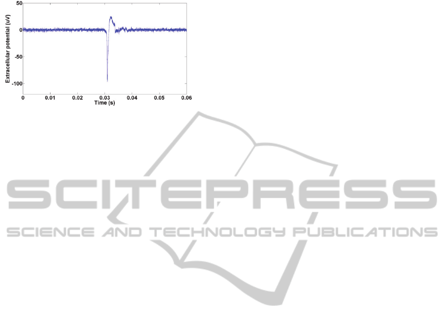
neurons on the MEA was further verified.
Figure 6: A spontaneous neuronal spike recorded from
electrode 11 in Figure 5.
4 CONCLUSIONS
Dielectrophoresis is used, with increasing frequency,
in combination with microdevices, to manipulate
biological cells. However, it is important to
understand the impact the implementation of DEP
may have on the viability of cells. In this work we
have investigated the viability of mouse
hippocampal neurons positioned on the electrodes of
microfabricated multi-electrode arrays after the
implementation of pDEP. We showed that neurons
maintained high viability after short-term exposure
to cell-trapping solution, which contained, primarily,
10% sucrose. With electric signal of appropriate
frequency and amplitude (such as 6Vpp and 10MHz),
neuron membrane breakdown was prevented during
the DEP process. Most importantly, we have
obtained electrical signals from the neurons
positioned on the MEA, 12 hours after using positive
dielectrophoresis, further confirming the health and
electrically active properties of neurons.
ACKNOWLEDGEMENTS
This work was partially funded by National Science
Foundation (NSF) grant NSF ECCS-1321356 and a
grant to Lehigh University from the Howard Hughes
Medical Institute (HHMI) through the Precollege
and Undergraduate Science Education Program.
REFERENCES
Berdondini, L., Imfeld, K., Maccione, A., Tedesco, M.,
Neukom, S., Koudelka-Hep, M., and Martinoia, S.,
2009. Active pixel sensor array for high spatio-
temporal resolution electrophysiological recordings
from single cell to large scale neuronal networks. Lab
Chip, 9, 2644–2651.
Buzsaki, G., Anastassiou, C. A., and Koch, C., 2012. The
origin of extracellular fields and currents – EEG,
ECoG, LFP and spikes. Nat. Rev. Neurosci., 13, 407-
420.
Chitwood, R. A., Hubbard, A., and Jaffe, D. B., 1999.
Passive electrotonic properties of rat hippocampal
CA3 interneurones. J. Physiol., 515(3), 743-756.
Gagnon, Z. R., 2011. Cellular dielectrophoresis:
applications to the characterization, manipulation,
separation and patterning of cells. Electrophoresis, 32,
2466-2487.
Gentet, L. J., Stuart, G. J., and Clements, J. D., 2000.
Direct measurement of specific membrane capacitance
in neurons. Biophys. J., 79, 314-320.
Gupta, V., Jafferji, I., Garza, M., Melnikova, V. O.,
Hasegawa, D. K., Pethig, R., and Davis, D. W., 2012.
ApoStream, a new dielectrophoretic device for
antibody independent isolation and recovery of viable
cancer cells from blood. Biomicrofluidics, 6, 024133.
Heida, T., Vulto, P., Rutten, W. L. C., and Marani, E.,
2001. Viability of dielectrophoretically trapped neural
cortical cells in culture. J. Neurosci. Methods, 110, 37-
44.
Heida, T., Wagenaar, J. B., Rutten, W. L. C., and Marani,
E., 2002. Investigating membrane breakdown of
neuronal cells exposed to nonuniform electric fields by
finite-element modeling and experiments. IEEE Trans.
Biomed. Eng., 49(10), 1195-1203.
Ho, C. T. et al., 2013. Liver-cell patterning lab chip:
mimicking the morphology of liver lobule tissue. Lab
Chip, 13, 3578-3587.
Hochberg, L. R. et al., 2006. Neuronal ensemble control of
prosthetic devices by a human with tetraplegia. Nat.,
442, 164–171.
Honegger, T., Scott, M. A., Yanik, M. F., and Voldman,
J., 2013. Electrokinetic confinement of axonal growth
for dynamically configurable neural networks. Lab
Chip, 13, 589-598.
Huang, C., Liu, C., Loo, J., Stakenborg, T., and Lagae, L.,
2014. Single cell viability observation in cell
dielectrophoretic trapping on a microchip. Appl. Phys.
Lett., 104, 013703.
Jaber, F. T., Labeed, F. H., and Hughes, M. P., 2009.
Action potential recording from dielectrophoretically
positioned neurons inside micro-wells of a planar
microelectrode array. J. Neurosci. Methods, 182, 225-
235.
Jeng, C. P., Huang, C. T., and Shih, H. Y., 2010.
Hydrodynamic separation of cells utilizing insulator-
based dielectrophoresis. Microsystem Technologies,
16(7), 1097-1104.
Jones, T. B., 1995. Electromechanics of Particles,
Cambridge University Press. New York, pp. 34-81.
LaLonde, A., Romero-Creel, M. F., and Lapizco-Encinas,
B. H., 2014. Assessment of cell viability after
manipulation with insulator-based dielectrophoresis.
Electrophoresis, 35, 1-6.
BIODEVICES2015-InternationalConferenceonBiomedicalElectronicsandDevices
76

Li, M., Li, W. H., Zhang, J., Alici, G., and Wen, W., 2014.
A review of microfabrication techniques and
dielectrophoretic microdevices for particle
manipulation and separation. J. Phys. D: Appl. Phys.,
47, 063001.
Lu, J., Barrios, C. A., Dickson, A. R., Nourse, J. L., Lee,
A. P., and Flanagan, L. A., 2012. Advancing practical
usage of microtechnology: a study of the functional
consequences of dielectrophoresis on neural stem
cells. Integr. Biol., 4, 1223-1236.
Major, G., Larkman, A, U., Jonas, P., Sakmann, B., and
Jack, J. J., 1994. Detailed passive cable models of
whole-cell recorded CA3 pyramidal neurons in rat
hippocampal slices. J. Neurosci., 14(8), 4613-4638.
Pethig, R., 2010. Review article-dielectrophoresis: status
of the theory, technology, and applications.
Biomicrofluidics, 4, 022811.
Pohl, H. A., 1978. Dielectrophoresis: The behavior of
neutral matter in nonuniform electric fields,
Cambridge University Press. New York.
Prieto, J. L., Lu, J., Nourse, J. L., Flanagan, L. A., and
Lee, A. P., 2012. Frequency discretization in
dielectrophoretic assisted cell sorting arrays to isolate
neural cells. Lab Chip, 12, 2182-2189.
Rozitsky, L., Fine, A., Dado, D., Nussbaum-Ben-Shaul,
S., Lenvenberg, S., and Yossifon, D., 2013.
Quantifying continuous-flow dielectrophoretic
trapping of cells and micro-particles on micro-
electrode array. Biomed. Microdevices, 15, 859-865.
Spira, M. E., and Hai, A., 2013. Multi-electrode array
technologies for neuroscience and cardiology. Nat.
Nanotech., 8, 83-94.
Stevenson, I. H., and Kording, K. P., 2011. How advances
in neural recording affect data analysis. Nat.
Neurosci., 14, 139-142.
Vahey, M. D., and Voldman, J., 2009. High-throughput
cell and particle characterization using isodielectric
separation. Anal. Chem., 81(7), 2446-2455.
Viventi, J. et al., 2011. Flexible, foldable, actively
multiplexed, high-density electrode array for mapping
brain activity in vivo. Nat. Neurosci., 14, 1599-1605.
Yoshimura, Y., Tomita, M., Mizutani, F., and Yasukawa,
T., 2014. Cell pairing using microwell array electrodes
based on dielectrophoresis. Anal. Chem., 86(14),
6818-6822.
Zimmermann, U., and Neil, G. A., 1996.
Electromanupulation of Cells, CRC Press. Florida.
Zhou, T., and Tatic-Lucic, S., 2012. On application of
positive dielectrophoresis and microstructure
confinement on multielectrode array with sensory
applications. In Proc. IEEE Sensors Conf., Taipei,
Taiwan.
Zhou, T., Petryna, S., Fluck, V., Perry, S. F., and Tatic-
Lucic, S., 2014. Separation and assisted patterning of
hippocampal neurons from glial cells using positive
dielectrophoresis. In submission.
OnCombiningtheDielectrophoresisandMicrodevices-InvestigationofHippocampalNeuronalViabilityafter
ImplementingDielectrophoreticPositioningonMulti-ElectrodeArrays
77
