
Carbon Nanotubes
The Challenges of the First Syntheses Trials
C. A. Coelho
1
*, A. T. Sepúlveda
2
, L. A. Rocha
3
and A. F. Silva
4
1
School of Engineering, University of Minho, Guimarães, Portugal
2
Institute for Polymers and Nanocomposites/I3N, University of Minho, Guimarães, Portugal
3
Department of Industrial Electronics, School of Engineering, University of Minho, Guimarães, Portugal
4
MIT Portugal Program, School of Engineering, University of Minho, Guimarães, Portugal
Keywords: Carbon Nanotubes (CNTs), Biomedical Applications.
Abstract: Carbon nanotubes (CNTs), due to their unique properties, are suitable for application in biomedical devices.
However these devices are not available in the market because of problems associated with biocompatibility
and synthesis reproducibility. Indeed, the production of vertically aligned-carbon nanotubes (VA-CNTs) is
needed for most of these applications. The most common synthesis method, Chemical Vapor Deposition
(CVD), involves a large number of parameters, not all known, and their influence on the process is not fully
understood. Knowing that the synthesis of CNTs is performed in a variety of lab conditions and in different
furnace systems, which makes it impossible to create a universal recipe for use in all labs, this paper aims to
start the design of an universal protocol that all labs can use to generate a suitable recipe for their
environmental conditions and furnace system. The influence of parameters such as best deposition spot and
tube baking was assessed. During this evaluation, the importance of other factors (catalyst uniformity and
climacteric conditions) to the process has been revealed. The universal protocol suggested is in an early
stage and needs to be improved.
1 INTRODUCTION
Nowadays, carbon nanotubes (CNTs) are one of the
most promising and exciting materials in
nanomaterials research field, own to their unique
electrical, mechanical and chemical properties.
These properties make CNTs suitable for many
biomedical applications (Raffa et al., 2011).
Indeed, CNTs found application in scaffolds for
tissue engineering (Tran et al., 2009), namely for
bone (Newman et al., 2013) and nervous tissue
repair and regeneration (Fabbro et al., 2013). CNTs
can also be used as drug and gene delivery devices
(Tran et al., 2009).
There are several reports about electrochemistry
biosensors for medical purposes that include CNTs
on its electrodes (Jacobs et al., 2010). Biofuel cells
work similarly to the enzymatic biosensors, so
naturally CNTs were included in these devices
(Holzinger et al., 2012). Others applications reported
are neuronal electrode interfacing (Bareket-Keren
and Hanein, 2012), microfluidic devices (Chen et al.,
2012), carbon nanotubes-based X-rays devices
(Calderón-Colón et al., 2009) and flexible pressure
sensors (Sepúlveda et al., 2011).
The list of applications of CNTs on the field of
medical devices is vast but despite this growing
research, CNTs still suffer from two main hurdles:
i) the biocompatibility and ii) the synthesis
reproducibility (the focus of this paper).
The majority of the listed devices require the
incorporation of vertically aligned-carbon nanotubes
(VA-CNTs). The most common synthesis process
for the production of CNTs with this arrangement is
Chemical Vapor Deposition (CVD). This process
involves a large number of parameters and some of
them may be still unknown. The ways that these
parameters influence each other and the process are
not completely understood (Oliver et al., 2013).
Furthermore, CVD process is many times
performed in non-cleaning environments so the
ambient conditions of each lab influences the
synthesis as so the furnace system (Oliver et al.,
2013). There are many different furnace systems and
their geometry and function affect the process. So,
these variations between labs prevent the
95
Coelho C., Sepúlveda A., Rocha L. and Silva A..
Carbon Nanotubes - The Challenges of the First Syntheses Trials.
DOI: 10.5220/0005201000950102
In Proceedings of the International Conference on Biomedical Electronics and Devices (BIODEVICES-2015), pages 95-102
ISBN: 978-989-758-071-0
Copyright
c
2015 SCITEPRESS (Science and Technology Publications, Lda.)
reproducibility of results.
Because of the differences in ambient conditions
and in furnace systems between labs, it is not
possible to make a general recipe that can be used in
all labs, achieving the same results. Instead, one
needs to create a universal protocol that can enable
each lab to evaluate the influence of the parameters
in its own environment, and create a recipe
appropriate for its system.
This paper pretends to give an initial insight on
how this protocol can be performed. For that the
influence of the best deposition spot and tube baking
were evaluated. During the evaluation of these
parameters, others factors revealed to be important
for the process such as the catalyst uniformity and
the climacteric conditions.
2 CNT SYNTHESIS
There are several techniques to grow VA-CNTs, but
the most common one among the different research
groups is based on a modified CVD system. In a
broad sense, in this technique, a carbon precursor in
its gaseous form flows inside a tube at elevated
temperature and enters in contact with a catalyst
(Figure 1).
Figure 1: Furnace CVD system. Adapted from Hart, 2007.
Catalysts are used with two purposes: have an
on-site pyrolysis of the precursor and support the
CNTs during and after growth. The most important
properties when selecting a material for catalyst are
its ability to dissolve carbon at elevated
temperatures, the carbon diffusion rate, the melting
point and the equilibrium vapor pressure (Jourdain
and Bichara, 2013). Among the most common
catalysts, one can find Fe, Ni and Co, which are
transition metals that reveal high solubility for
carbon (Hart, 2007).
A thin-film of catalyst is deposited on a substrate
where one desires to grow the CNTs. The most
common one is silicon due to its compatibility with
the catalysts and due to the melting point higher than
the process temperature.
The CVD synthesis process requires the use of
three gases: the carbon precursor, a reducing gas and
an inert one.
The precursor provides the carbon for the CNTs
formation. This gas can be an hydrocarbon (Wang et
al., 2014), an alcohol (Chen et al., 2014), an
aromatic compound (Atiyah et al., 2011) or a natural
carbon source (Qiao-juan et al., 2013).
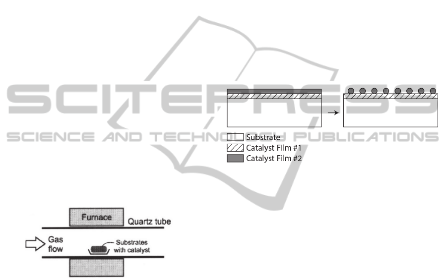
The reducing gas, as the name implies, reduces
the oxide that forms when the catalyst is not well
stored. Also, it helps the formation of the catalyst
nanoparticles and it keeps the catalytic sites active
during all the growth process (Figure 2).
The inert gas is used during the process to
control the pressure inside the tube if needed, and as
a cleaning gas at the beginning and at the end of the
synthesis process. Furthermore, it helps heat transfer
during heating or cooling stages.
Figure 2: Formation of the catalyst nanoparticles by the
action of hydrogen. Adapted from Hart 2007.
The CNT synthesis process can be divided into
five stages (Figure 3): the cleaning, the dewetting,
the growth, the delamination and the cooling.
The first stage consists on the cleaning of the
lines, with the respective circulating gas, and of the
tube with an inert gas.
The second one involves heating the tube to
operating temperature and the catalyst reduction. In
this stage there is also the formation of the catalyst
nanoparticles, the dewetting step (Figure 2). The size
of these nanoparticles is very important, because it
will determine the diameter, the number of walls and
the alignment of the CNTs (Jourdain and Bichara,
2013; Hart, 2007). The size can be controlled
through the control of the temperature, flow and
exposure time to the reducing gas. After this stage,
the flow of the reducing gas is kept steady to
maintain the catalytic sites active during the next
step.
The third stage is the growth itself. The carbon
precursor starts to flow in the tube and its
degradation occurs by temperature and catalyst
actions. The carbon resulting of these actions is
adsorbed in the catalyst nanoparticles and
precipitates when the particle is saturated, beginning
the growth (Hart, 2007). The growth stops when the
particle is encapsulated by amorphous carbon and
BIODEVICES2015-InternationalConferenceonBiomedicalElectronicsandDevices
96
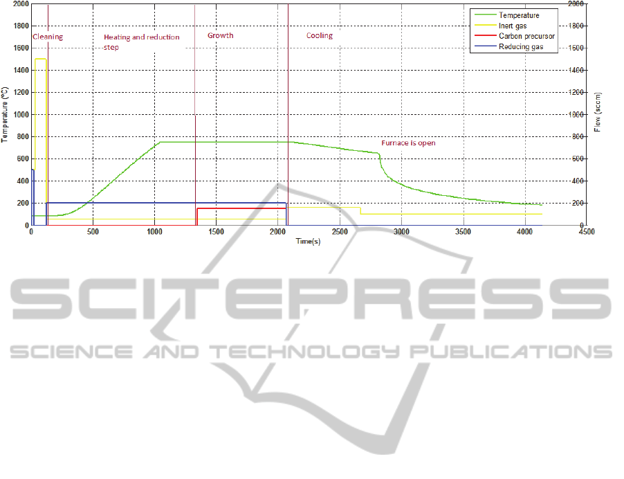
Figure 3: Steps of growth process.
other carbon compounds that form during this
process (Brukh and Mitra, 2006).
The previous stages are the most important for
the overall process. There can be an optional step,
the delamination, which eases the removal of CNTs
from the substrate.
The last stage is the cooling. Only the inert gas
flows inside the tube to assist the heat transfer and to
clean the gases and the wastes that remain in the
tube. The CNTs can only be removed from the tube
when the temperature cools down.
The equipment used for CNTs growth was a
furnace Nabertherm, model RS 80/750/11, which is
connected to three valves MKS Instruments, model
RS-485, that control the gases flow. This setup is
connected to a computer which controls the heating
and cooling of the furnace as well as the flows.
The quartz tube used in this study had 25 mm of
internal diameter and a length of 1000 mm. The
selected gases were ethylene as the precursor gas,
hydrogen as the reducing gas and helium.
Thin-films of alumina and iron, 10 and 1 nm
thick respectively, were deposited via e-beam
technique on top of the Si wafer as catalysts.
3 PROCESS PARAMETERS
From the previous section, one easily identifies a
number of parameters that can be tuned to set the
CNTs synthesis. Figure 3 illustrates a standard
recipe for CNT growth via CVD technique.
3.1 Gases Flow/Time
Ethylene, hydrogen and helium are the gases used in
this study.
Helium is the inert gas with the main role of
cleaning and assist the heat transfer inside the tube.
The ethylene is the carbon precursor. Its flow
inside the tube is a key parameter. When selecting
the flow, it must be taken into account that lower
flows mean higher residence time and more
probability of the reactions needed to form CNTs to
occur, than if we had higher flows. However, at the
other hand, it decreases the refresh rate of the gas
inside the tube (Brukh and Mitra, 2006). Another
aspect is the heights of CNTs forests increase with
the growth time but not in a linear fashion. Indeed,
from a certain time, forests are not higher because
the catalyst nanoparticles are encapsulated in
amorphous carbon, preventing them from degrading
more ethylene and adsorb more carbon (Kumar and
Ando, 2010).
The time and the flow of hydrogen influence the
size of catalyst nanoparticles, which in turn
influence the diameter, the number of walls and the
alignment of CNTs (Jourdain and Bichara, 2013;
Hart, 2007). In the growth step, this gas is essential
for keeping the catalytic sites active.
3.2 Temperature
Temperature also affects the process as it is involved
in the reduction process of the oxide and in the
ethylene’s pyrolysis.
It is important to understand the temperature
profile inside the tube and to have it correlated to the
length of the tube. In order to minimize the variation
of the temperature inside the oven towards the tube
endings, the furnace has isolation sleeves at the tube
endings that not only ensure the tube centering
CarbonNanotubes-TheChallengesoftheFirstSynthesesTrials
97
inside the oven cavity but also minimize the
temperature loss towards the exterior.
Because the synthesis process is based on
chemical reactions, one should not forget that there
are thermal and chemical inertia associated with the
reactions.
3.3 Silicon Pieces
The positioning of the pieces inside the tube also
affects the growth process. The ethylene’s
degradation occurs driven by temperature and
catalyst actions. There is thermal and chemical
inertia, so the initial part of the tube is not the best
place for the positioning of the pieces. As the gases
enter in the tube at room temperature, it is necessary
to consider the time required for the gas to achieve
the required temperature. This requires time, which
in a continuous flow, forces the pieces to be
positioned towards the tube’s downstream side.
However, as the ethylene travels along the tube
undergoes air pyrolysis driven by temperature. The
resulting compounds can be adsorbed on the catalyst
nanoparticles to form CNTs or may continue to
travel along the tube. If the latter is verified, they
begin to recombine into more complex molecules
that can contribute to the encapsulation of the
catalyst nanoparticles, and consequently to the end
of growth (Brukh and Mitra, 2006). This suggests
that the closer the end of the tube pieces are placed,
the lower the height of the CNT forests obtained.
The identification of the growth “sweet spot” in
the tube is key to ensure a reproducible and
consistent synthesis process.
3.4 Other
Tube baking is another parameter that affects the
growth, but its influence is not well established.
After a growth, there are a few residues that still
remain in the tube. If they are left in the tube they
may influence the next growth session. To minimize
the impact of the debris, a tube baking is performed.
To do so, the tube, while open, is raised up to 750 ºC
for 10 minutes. This process burns all the residues
inside the tube, leaving it cleaned. This baking
process can be seen as a strategy to reset the tube.
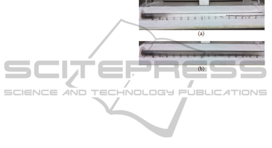
Figure 4 shows the accumulation of debris after
three growth sessions, as an example.
4 APPROACH/STRATEGY
This paper reports the study to identify the best
positioning inside the tube for CNTs’ synthesis and
the influence of tube baking during the process.
These two parameters are standard to anyone who
begins to synthesize CNTs in a laboratory.
For the realization of such study, a test protocol
was established. In each working day, one would
perform three growths and do a reset (bake) at the
end of the day.
Figure 4: Aspect of the tube a) after the bake, b) after three
growth sessions.
In each session, two pieces would be placed
inside the tube. These pieces were cleaned with
alcohol, acetone and nitrogen prior to their
placement. The silicon pieces had all the same
dimensions (10 mm x 10 mm) and were positioned
with a distance of 10 mm between them. These
pieces provide sufficient catalyst volume to trigger
the local pyrolysis.
In order to start the study, it was necessary to set
a starting recipe for the CNTs growth. The starting
recipe consisted in a dewetting time of 5 min, with a
flow of hydrogen of 200 sccm. At the same time, the
tube was heated until its temperature reached
750 ºC. The growth duration was of 12 min and the
ethylene’s flow in this stage was of 150 sccm. In the
beginning of the recipe, the tube was cleaned with
helium, which was also used at the end while the
tube was cooling down. This recipe was based on
literature review compilation and comparison (Stein
and Wardle, 2013; Wardle et al., 2008; Garcia et al.,
2008).
The height of the CNTs forests produced was
measured using a magnifying glass of the brand
LEICA, model M-80.
For the analysis of morphology of some samples
and their chemical characterization, it was
performed SEM analysis by a microscope Nova
NanoSEM 200, FEI Company. This microscope has
integrated an Energy Dispersive Spectrometer
(EDS), which allows the chemical characterization
of the samples by the analysis of its X-ray spectrum.
BIODEVICES2015-InternationalConferenceonBiomedicalElectronicsandDevices
98
5 RESULTS AND DISCUSSION
The first parameter to be evaluated was position.
Knowing that there is a certain degree of thermal
and chemical inertia as said before, the pieces were
positioned from the center of the tube (position 0
mm) towards the downstream in the direction of
gases flow. The stopping criterion was the
identification of a deflection point on the height’s
trends along the tube.
The main objective of the evaluation of this
parameter was to identify the location within the
tube where the CNTs obtain the greatest height and
where the results show less variation.
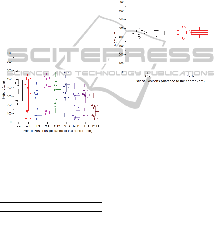
Figure 5 shows the heights of the produced
CNTs forests as a function of pieces position inside
the tube, using the starting recipe.
Figure 5: Height of the obtained CNTs forests in function
of pairs of position of the pieces inside the tube.
Although Figure 5 shows some trend, one can
argue that the variation of heights among the
samples is large for the height average (Table 1).
This non consistency growth led to the thought that
it was not related to the growth parameters but
instead to the catalyst deposition.
Table 1: Pairs samples’ values for average and standard
deviation.
Position
Height Average
(µm)
Standard
Deviation
Standard
Deviation (%)
0-2 410 134.9 32.9
2-4 336 199.0 59.2
4-6 245 131.4 53.6
6-8 346 188.2 54.4
8-10 345 115.6 33.5
10-12 399 103.6 26.0
12-14 168 129.8 77.3
14-16 286 104.0 36.4
16-18 124 66.8 53.9
In order to sort the above issue, a new wafer with
new catalysts films was requested from other
supplier (INESC MN) that had fine control of the
deposition process.
With the new samples, the growths were
repeated for the positions 8-10 and 10-12 (Figure 6),
the ones that were considered from the first set of
growths to be the most relevant.
Figure 6: Height of the obtained CNTs in function of pairs
of position of the pieces inside the tube for the case of the
revised catalysts deposition.
As one can observe, the standard deviation was
drastically reduced (Table 2), which confirms that
the problem verified with the previous study was
caused by the non-uniformity of catalyst deposition.
Since both pairs of position have low standard
deviations and considering that the pair 10-12 has
the highest height average, this pair was chosen has
the best deposition spot for the current system.
Table 2: Pairs samples’ values for average and standard
deviation for the case of the revised catalysts deposition.
Position
Height Average
(µm)
Standard
Deviation
Standard
Deviation (%)
8-10 443 26.3 5.9
10-12 454 43.1 9.5
Probably after position 12, phenomena of
formation of complex molecules are occurring,
consuming the precursor available and leading to the
encapsulation of the catalyst nanoparticles, and
consequently, to the reduction of the height of
forests as seen in the Figure 5 graphic.
Since its entrance on the tube, the ethylene is
suffering aerial pyrolysis. The resulting products
(carbon and/or carbon compounds) can be adsorbed
in the catalyst nanoparticles as well as ethylene
which did not react. These compounds will undergo
CarbonNanotubes-TheChallengesoftheFirstSynthesesTrials
99
catalyst pyrolysis. The results suggest that the
contribution of the two types of pyrolysis is
maximum in the pair of positions 10-12, reaching in
this place the forests with higher heights.
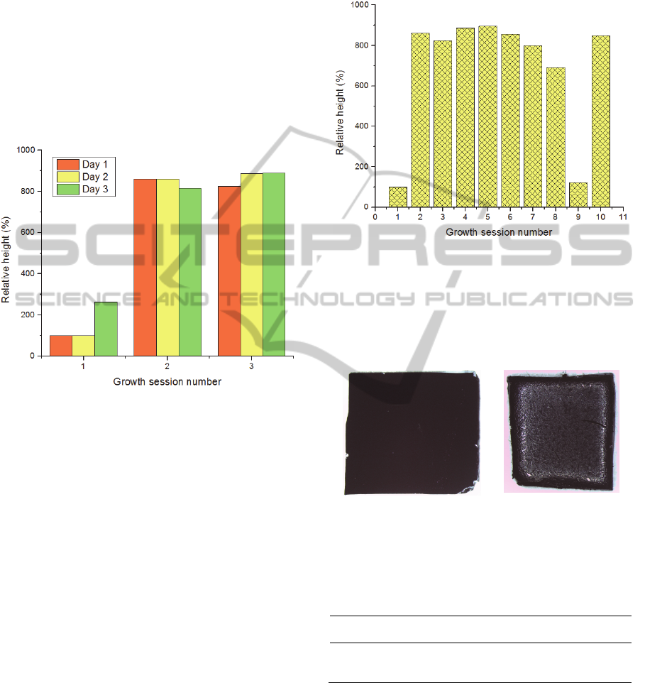
Next, the influence of the tube baking in the
forests’ height was tested. Figure 7 shows the
relative heights of three growth sessions realized
during three days. Note that the higher heights
obtained compared to the previous runs were due to
the increase of the ethylene time to 25 minutes. This
increase was performed in order to obtain tall forests
for the analysis.
Figure 7: Height (in percentage in respect to the first
growth of the first day) of CNTs in the 3 sessions
performed during 3 days.
The first session of each day presents always the
worst results. After this growth, the forests reach
greater heights. These results suggest that the first
session after cleaning the tube leaves some residues,
which are essential for the next growths.
In order to further evaluate this, it was tested
how long the tube could go in terms of growth
sessions without performing the baking (Figure 8).
In the graphic of Figure 8 it is possible to see that
after the fifth growth the heights of CNTs begin to
decrease. Seeing that there is residues accumulation
in the tube since the first growth, after 125 min of
ethylene (cumulative time from all sessions), the
amount of residues inside the tube becomes
noticeable and starts to deposit on the top of the
forests, preventing the precursor from reaching the
catalyst nanoparticles.
Observing the SEM images (Figure 10a and
Figure 10b), this color change seems to be caused
not only by the deposition of carbon with a different
structural arrangement, but also by the presence of
other substances. The analysis of X-ray spectra in
the regions indicated in Figure 10(c) and (d) was
performed to check if there are other substances
present at the top of the forests. The results are
shown in the Table 3.
Figure 8: Height of CNTs, in percentage in respect to the
first growth, during 10 sessions without cleaning the tube.
The deposition of debris was confirmed by
observing a color change in the forests for a gray
tone (Figure 9) and by the analysis of the X-ray
spectrum held by SEM (Figure 10 and Table 3).
a)
b)
Figure 9: a) Piece with normal color, b) piece with gray
tones.
Table 3: Results of the chemistry analysis performed on
the regions Z1, Z2 e Z3 by the determination of the
respective X-ray spectrum.
Region
Mass percentage (%)
Carbon Oxygen
Z1 97.60 2.40
Z2 97.75 2.25
Z3 92.10 7.90
It was found that, in addition to carbon, there is
also oxygen. This oxygen may result from the
reduction step where the iron oxide is reduced to
iron. In this step occurs the formation of hydroxides,
which eventually settle on the top of the forests.
Despite their different aspect, the regions Z1 and Z2
have similar chemical compositions, suggesting that
the morphological differences between these two
BIODEVICES2015-InternationalConferenceonBiomedicalElectronicsandDevices
100
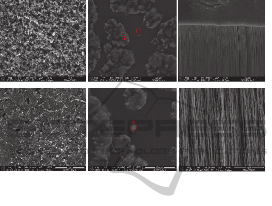
a)
c)
e)
b)
d)
f)
Figure 10: SEM images of the top view of CNTs forests after: (a) 5 sessions; (b) 7 sessions without performing tube baking.
c) Regions Z1 e Z2 on the top of the forests where were performed X-ray spectrometry analysis. d) Region Z3 where was
performed X-ray spectrometry analysis. e) and f) Lateral view of CNTs. It is possible to observe the: (e) the alignment; (f)
the waving.
regions are due to carbon deposition with a different
structural arrangement. So, the visible
morphological changes are due to not only the
presence of hydroxides but also to the deposition of
carbon with a different structural arrangement.
Despite the effect on the top of the CNTs forest,
a cross section view of the forests shows the vertical
alignment (Figure 10e and Figure 10f).
6 CONCLUSIONS
From the results obtained in the parametric study is
possible to start a universal protocol for generate the
best recipe for each system and for each lab.
Throughout the analysis of the best deposition
site, problems related with the non-uniformity of the
catalyst film deposition were raised. These problems
emphasize the importance of this key step. The
deposition of the catalyst film must be of high
quality in terms of uniformity and thickness to
ensure, respectively, the uniformity of the forest
itself and the CNTs alignment. The catalyst should
be protected of the environment, for example, by
photoresist, to avoid its oxidation and the formation
of undesirable substances during the synthesis that
can affect the morphology and properties of the
forests.
About the protocol itself, first one should
established a starting recipe based on literature
review and accordingly to the system characteristics.
After that, the first parameter to be evaluated should
the best deposition spot, taking into account the
reactions that the precursor suffers since it enters the
tube.
After finding the best deposition spot, the
starting recipe should be adjusted to this position in
terms of fluxes and growth time. Then, one should
evaluate how far the system can go in terms of
growth sessions without doing the baking. After
controlling all these parameters, one should study
the way in which the heights vary with the ethylene
time. This step enables the control of the forest
height in accordance.
This paper presents an initial approach on how to
perform a parametric study.
CarbonNanotubes-TheChallengesoftheFirstSynthesesTrials
101

More work has to be developed for answering
some questions that have risen, namely at the room
humidity and temperature level, which reveled some
influence on the on the process but that was not able
to be monitor at the time.
About the tube baking, there is the need to
understand why, in this system, the residues left on
the tube in the first growth are essential and improve
the results in the next sessions and what residues are
those. An approach to “see” inside the tube should
be created in order to evaluate the substances
remaining in the tube after the growths and how they
behave to contribute to reducing the heights
obtained.
The universal protocol proposed in this paper is
only an initial model, which still needs to be
improved by solving the raised questions and by
enhancing the parametric study developed.
ACKNOWLEDGEMENTS
The authors wish to thank FCT – Fundação para a
Ciência e Tecnologia, Portugal, for the financial
support provided under the project PTDC/EEI-
ELC/1838/2012.
The authors would like to acknowledge INESC-
MN for the deposition of catalysts thin-films.
REFERENCES
Atiyah, M. R. et al., 2011. Low Temperature Growth of
Vertically Aligned Carbon Nanotubes via Floating
Catalyst Chemical Vapor Deposition Method. Journal
of Materials Science & Technology, 27(4), pp.296–
300.
Bareket-Keren, L. & Hanein, Y., 2012. Carbon nanotube-
based multi electrode arrays for neuronal interfacing:
progress and prospects. Frontiers in neural circuits,
6(January), p.122.
Brukh, R. & Mitra, S., 2006. Mechanism of carbon
nanotube growth by CVD. Chemical Physics Letters,
424(1-3), pp.126–132.
Calderón-Colón, X. et al., 2009. A carbon nanotube field
emission cathode with high current density and long-
term stability. Nanotechnology, 20(32), p.325707.
Chen, G. D. et al., 2012. Nanoporous micro-element
arrays for particle interception in microfluidic cell
separation. Lab on a chip, 12(17), pp.3159–67.
Chen, R. et al., 2014. Production of hydrogen-rich gas and
multi-walled carbon nanotubes from ethanol
decomposition over molybdenum modified Ni/MgO
catalysts. Journal of Energy Chemistry, 23(2), pp.244–
250.
Fabbro, A., Prato, M. & Ballerini, L., 2013. Carbon
nanotubes in neuroregeneration and repair. Advanced
drug delivery reviews, 65(15), pp.2034–44.
Garcia, E. et al., 2008. Fabrication and multifunctional
properties of a hybrid laminate with aligned carbon
nanotubes grown In Situ. Composites Science and
Technology, 68(9), pp.2034–2041.
Hart, A. J., 2007. Chemical, Mechanical, and Thermal
Control of Substrate-Bound Carbon Nanotube
Growth. Massachussets Institute of Technology.
Holzinger, M., Le Goff, A. & Cosnier, S., 2012. Carbon
nanotube/enzyme biofuel cells. Electrochimica Acta,
82, pp.179–190.
Jacobs, C. B., Peairs, M. J. & Venton, B. J., 2010. Review:
Carbon nanotube based electrochemical sensors for
biomolecules. Analytica chimica acta, 662(2), pp.105–
27.
Jourdain, V. & Bichara, C., 2013. Current understanding
of the growth of carbon nanotubes in catalytic
chemical vapour deposition. Carbon, 58, pp.2–39.
Kumar, M. & Ando, Y., 2010. Chemical Vapor Deposition
of Carbon Nanotubes: A Review on Growth
Mechanism and Mass Production. Journal of
Nanoscience and Nanotechnology, 10(6), pp.3739–
3758.
Newman, P. et al., 2013. Carbon nanotubes: their potential
and pitfalls for bone tissue regeneration and
engineering. Nanomedicine : nanotechnology, biology,
and medicine, 9(8), pp.1139–58.
Oliver, C. R. et al., 2013. Statistical analysis of variation
in laboratory growth of carbon nanotube forests and
recommendations for improved consistency. ACS
nano, 7(4), pp.3565–80.
Qiao-juan, G. et al., 2013. Catalytic growth of multi-wall
carbon nanotubes on carbon cloth using powdery
ferrous sulfate heptahydrate as catalyst precursor. New
Carbon Materials, 28(6), pp.421–427.
Raffa, V. et al., 2011. Carbon Nanotubes for Biomedical
Applications R. Klingeler & R. B. Sim, eds., Berlin,
Heidelberg: Springer Berlin Heidelberg.
Sepúlveda, a T. et al., 2011. Nanocomposite Flexible
Pressure Sensor for Biomedical Applications.
Procedia Engineering, 25, pp.140–143.
Stein, I. Y. & Wardle, B. L., 2013. Coordination number
model to quantify packing morphology of aligned
nanowire arrays. Physical chemistry chemical
physics : PCCP, 15(11), pp.4033–40.
Tran, P. a, Zhang, L. & Webster, T. J., 2009. Carbon
nanofibers and carbon nanotubes in regenerative
medicine. Advanced drug delivery reviews, 61(12),
pp.1097–114.
Wang, Y. et al., 2014. Quantum chemical simulations
reveal acetylene-based growth mechanisms in the
chemical vapor deposition synthesis of carbon
nanotubes. Carbon, 72, pp.22–37.
Wardle, B. L. et al., 2008. Fabrication and
Characterization of Ultrahigh-Volume- Fraction
Aligned Carbon Nanotube-Polymer Composites.
Advanced Materials, 20(14), pp.2707–2714.
BIODEVICES2015-InternationalConferenceonBiomedicalElectronicsandDevices
102
