
Targeted Radiation Dipole Antenna using 3D Numerical Simulation
in Microwave Ablation
Hussein Alnassan
1,2
, Adrian Kastler
1
, Xia Wang
1
and Bruno Kastler
1,3
1
Laboratory I.4.S -EA 4268, Franche Comté Universty, Besançon, IFR 133, France
2
Electrical and Electronics Engineering Faculty, Aleppo University , Aleppo, Syria
3
Interventional Radiology Unit University Hospital Besançon, Besançon, France
Keywords: Microwave Ablation, Liver Tumors, Bone Microwave Ablation, Targeted Directional Radiation.
Abstract: Microwave ablation technology is being utilised in several medical applications for ablation therapy and
other applications. Microwave energy generates fast and high temperatures sufficient and capable to
produce coagulation necrosis. Theoretical models by numerical simulation of microwave ablation is a
distinct step in the implementation of system design, as well as in the results analysis before the ablation
procedure. Furthermore, these models play a role in design the microwave antennas. Classic microwave
ablation antenna around its radiating section applies electromagnetic field in tumors without worry about
near neural structures. This paper presents the temperature distributions of targeted radiation dipole antenna
model with active and non-active sides for microwave ablation at 2.45GHz at different powers and ablation
times. Temperature maps and SAR distributions around the radiating section show in two sides.
1 INTRODUCTION
Thermal ablation technology is an alternative to
surgical resection for destruction of several types of
tumors. Thermal ablations could be using many
energy sources, including laser, high intensity
focused ultrasound, radiofrequency and microwave.
While radiofrequency has been the most applied in
clinical thermal ablation, microwave ablation has
several advantages including, faster heating of large
tumors, less susceptibility to heat-sink effect and no
ground pads requirement.
Efficiency of minimally invasive percutaneous
thermal microwave ablation (MWA) has been
proved in treating several types of tumor including
the liver, lung, kidney (Kuang et al. 2007; Wolf et
al. 2008; Castle, Salas, and Leveillee 2011) and
recently bone (Kastler et al. 2013; Kastler et al.
2014). The phenomenon of denaturation is induced
by tissue temperature rising above 50°C which
causes coagulation and cells death in a matter of
minutes (Brace 2009).
Several coaxial-based antenna have been
designed for microwave ablation including the slot
antenna (Ito et al. 2004), dipole antenna (Hurter,
Reinbold, and Lorenz 1991), monopole antenna
(Labonte et al. 1996), cap-choke antenna (Lin and
Wang 1996), floating sleeve antenna (Yang et al.
2006), triaxial antenna (Brace et al. 2007), and
minimally invasive antenna (Cavagnaro et al. 2011).
Clinical application and several microwave
ablation devices have been reviewed in (Lubner et
al. 2010). Microwave energy at 915MHz or
2.45GHz induces a phenomenon known as dielectric
hysteresis to create heat generation (rotation of
water, proteins and other polar molecules in tissues).
Computational simulation using commercial
software (HFSS or COMSOL..) have been used to
predict the electromagnetic fields from the antenna,
temperature profile in tissue, and to integrate
electromagnetic and thermal solutions for
understanding how the ablation zones form (Chiang,
Wang, and Brace 2013).
Some tumors may be located in proximity of
neural noble structures which may be damaged by
the ablation process (nerves, vessels, biliary
ducts…). Therefore, in this paper, we design and
simulate a coaxial antenna with directive radiation
by varying the directive windows angle during the
ablation. The analyses were performed by 3D finite
element modelling. In order to compare the results in
terms of power and application time, we have used a
tissue temperature distribution model. The targeted
radiation in MWA has been presented in (Thaiwat et
al. 2011) for slot antenna in different open angles
44
Alnassan H., Kastler A., Wang X. and Kastler B..
Targeted Radiation Dipole Antenna using 3D Numerical Simulation in Microwave Ablation.
DOI: 10.5220/0005209900440048
In Proceedings of the International Conference on Biomedical Electronics and Devices (BIODEVICES-2015), pages 44-48
ISBN: 978-989-758-071-0
Copyright
c
2015 SCITEPRESS (Science and Technology Publications, Lda.)

without however discussing lesion radius in the
active and non active side.
2 ANTENNA GEOMETRY
2.1 Structure
The goal was to design a coaxial antenna to realize
direction ablation on one side of antenna and prevent
it on the other side. The configuration and
dimensions of antenna geometry are presented in
Fig.1 and Table 1. To design our model, we chose
the coaxial dipole antenna model presented by yang
(Yang et al. 2006) without the sleeve as initial
antenna. We also were partly inspired by the work
presented in (“DIRECTIVE WINDOW ABLATION
ANTENNA WITH DIELECTRIC LOADING -
Patent - Europe PubMed Central” 2014). We have
inserted our antenna in a catheter with a dielectric
window at different lengths and angles opening. i.e.
8mm length and 300° angle. Our original idea was to
block the microwave energy by a metal catheter in
order to guide the wave to the desired directional
window for targeted tumoral ablating purposes.
We designed this model using Comsol 4.3
computer simulation for temperature distribution
around the antenna tip on two opposite sides (active
window side and non active side).
The model supposes that antenna is inserted in a
homogeneous liver block with diameter 50mm and
length 60mm. The dielectric insulator between inner
and outer conductors is Teflon with relative
permittivity equal to 2.03, and the dielectric window
is Ceramic with relative permittivity equal to 10 as
depicted in Fig. 2.
The parameters of material for the antenna and
liver are shown in Table 2. The liver parameters are
chosen in the static state without thermal effects on
the dielectric properties of tissue. All dielectric
properties value were taken from literatures
published static values.
2.2 Materials and Equations
Figure 1: Antenna top section with layers.
To simplify the design, all the conductors material of
the antenna were modelled using perfect electric
conductor (PEF) boundary conditions. The
microwave energy was chosen at 2.45GHz and
between power range 0-70W, with ablation duration
900 seconds.
We performed the simulation using the Finite
Element Method (FEM) Comsol 4.3 to solve our
Electromagnetic-Thermal problems. The mesh was
non uniform. A three dimension model was chosen
on platform Intel(R) Core(TM)2 Duo CPU P8400 @
2.26 GHz with RAM 4 GB.
The bioheat equation is represented in (1):
.
(1)
ρ Density of liver (kg/m
), C Heat capacity of
liver(J/kgk),K Thermal conductivity (W/mK), T
Temperature(°C),T
Temperature of blood
(°C),h
The convective heat transfer coefficient,Q
Energy from metabolic processes (W/m
),Q
External heat source (W/m
) (2).
SinceQ
is negligible, we excluded it from our
FE models. We also omitted T
from our
preliminary studies. The Specific Absorption Rate
SAR [W/kg] in tissue is calculated as a function of
position as follows (3):
/
(1)
// (2)
E Electric field (V/m),σ Conductivity of liver
(s/m).
Table 1: Radius of antenna layers.
Layer Radius(mm)
Inner Conductor
0.256
Dielectric
0.84
Outer Conductor
1.1
Air Cavity
1.3
Catheter
1.5
Figure 2: Antenna side section in a liver block.
3 SIMULATION RESULTS
3D Temperature distributions are shown in Fig.3
from active side section at different powers and after
TargetedRadiationDipoleAntennausing3DNumericalSimulationinMicrowaveAblation
45
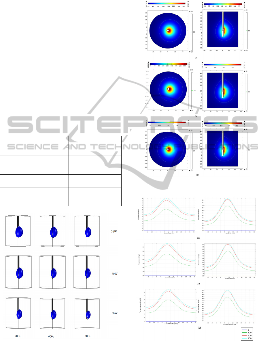
different application times we chose the temperature
level equal to 100°C.
The simulated lesion size is defined as the area
within the 50°C contour line, which corresponds to
actual ablation size. The Fig. 4 presents the
temperature distributions on active and opposite non
active sides of antenna tip at different powers after
900s and including contour 50°C. We can see non-
spherical lesion form around the antenna. These
lesions are in proportion with the power and
application time increase.
The temperature changes from active side and
opposite non active side at 10mm from antenna axis
at 0,300,600,900s and for powers 50, 60, 70W are
shown in Fig. 5. We see higher temperature level at
window side than the other side and the radius
increasing of lesion with the long duration of
ablation.
Table 2: Parameters of tissues.
Properties Values
(density of liver)
1060(kg/
(Heat capacity of liver)
3600(J/kgk)
K(Thermal conductivity of
liver)
0.56(W/mK)
(density of Blood)
1000(kg/
(Heat capacity of liver)
3639(J/kgk)
(Conductivity of liver)
1.69(S/m)
(Permittivity of liver)
43.3
(Permittivity of
dielectric)
2.03
Figure 3: three dimensions Temperature distributions from
top to down 70,60,50w and from left to right
900,600,300s.
Figure 4: Temperature distribution (a) 50W,(b) 60W,(c)
70W for 900s , 2 views.
Figure 5: Temperature value left, non active side right
active side (a)50W,(b)60W,(c)70W and ablation times
(300,600,900s).
BIODEVICES2015-InternationalConferenceonBiomedicalElectronicsandDevices
46
The temperature value increases with power
increases, and we see higher temperature peaks on
the active side comparing to the non active side.
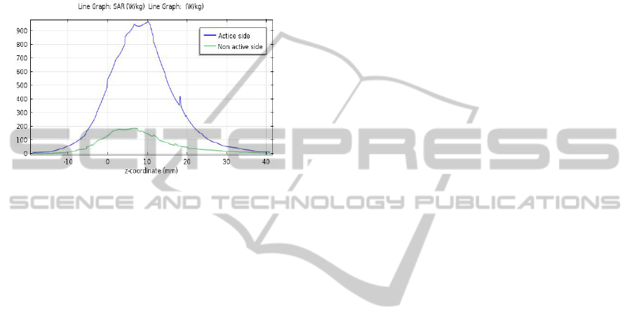
Fig. 6 shows the SAR values along the
longitudinal direction for the non active side (green)
and active side (blue) of antenna in the lesion
regions. SAR values indicate there are differences
between the two sides and these values are
constrained.
Figure 6: SAR values non active side (green) , active side
(blue).
4 DISCUSSION AND
CONCLUSIONS
In this study we designed a novel dipole antenna
inserted in an asymmetric metallic catheter with a
dielectric window. We tested the simulation of this
MW ablation antenna achieving a directional
ablation in liver model by using a 3D Finite
Elements Method (FEM) which analyses the
temperature distribution. We chose a dipole antenna
because with 3mm diameter allowing high power
delivery and large lesion size. A metal catheter was
chosen for two goals: First to guide the generated
electromagnetic waves to the dielectric window,
Second: to obtain an air cavity through which water
may be circulated for cooling purpose and to prevent
backward heating.
Increasing power application times from 600 to
900s did not significantly contribute to temperature
induced changes, nor did it affect lesion radius on
both active and non active side.
The antenna we elaborated can selectively ablate
tissue on the active side. The lesion size on active
side can be controlled by increasing power and
ablation duration until 600s.
The disadvantage of our antenna is the relatively
large diameter 3mm, however still compatible for
percutaneous bone or laparoscopic microwave
ablation.
In this work dipole antenna model radiates a
directive electromagnetic field, the goal is to achieve
a selective ablation while avoiding damaging the
healthy tissue structures near targeted tumour.
According to temperature values and SAR
distributions levels between active side and non
active-side show promising results in targeted
ablation.
These simulation results are considered as a first
step before implementation of our device. May be
more computational modeling and experimental
searches are needed to understand the dielectric and
thermal tissue properties, as well as to increase the
lesion size.
REFERENCES
Brace, Christopher L. 2009. “Radiofrequency and
Microwave Ablation of the Liver, Lung, Kidney, and
Bone: What Are the Differences?” Current Problems
in Diagnostic Radiology 38 (3): 135–43. doi:10.1067/
j.cpradiol.2007.10.001.
Brace, Christopher L., Paul F. Laeseke, Lisa A. Sampson,
Tina M. Frey, Daniel W. van der Weide, and Fred T.
Lee. 2007. “Microwave Ablation with a Single Small-
Gauge Triaxial Antenna: In Vivo Porcine Liver
Model.” Radiology 242 (2): 435–40. doi:10.1148/
radiol.2422051411.
Castle, Scott M., Nelson Salas, and Raymond J. Leveillee.
2011. “Initial Experience Using Microwave Ablation
Therapy for Renal Tumor Treatment: 18-Month
Follow-Up.” Urology 77 (4): 792–97. doi:10.1016/
j.urology.2010.12.028.
Cavagnaro, Marta, Claudio Amabile, Paolo Bernardi,
Stefano Pisa, and Nevio Tosoratti. 2011. “A
Minimally Invasive Antenna for Microwave Ablation
Therapies: Design, Performances, and Experimental
Assessment.” IEEE Transactions on Bio-Medical
Engineering 58 (4): 949–59. doi:10.1109/TBME.
2010.2099657.
Chiang, Jason, Peng Wang, and Christopher L. Brace.
2013. “Computational Modelling of Microwave
Tumour Ablations.” International Journal of
Hyperthermia 29 (4): 308–17. doi:10.3109/
02656736.2013.799295.
“DIRECTIVE WINDOW ABLATION ANTENNA
WITH DIELECTRIC LOADING - Patent - Europe
PubMed Central.” 2014. Accessed August 4.
http://europepmc.org/patents/PAT/CA2711827.
Hurter, W., F. Reinbold, and W.J. Lorenz. 1991. “A
Dipole Antenna for Interstitial Microwave
Hyperthermia.” IEEE Transactions on Microwave
Theory and Techniques 39 (6): 1048–54.
doi:10.1109/22.81680.
Ito, K., K. Saito, H. Yoshimura, Y. Aoyagi, and H. Horita.
2004. “Coaxial-Slot Antenna for Interstitial
Microwave Thermal Therapy and Its Application to
TargetedRadiationDipoleAntennausing3DNumericalSimulationinMicrowaveAblation
47

Clinical Trial.” Conference Proceedings: ... Annual
International Conference of the IEEE Engineering in
Medicine and Biology Society. IEEE Engineering in
Medicine and Biology Society. Conference 4: 2526–
29. doi:10.1109/IEMBS.2004.1403727.
Kastler, Adrian, Hussein Alnassan, Sébastien Aubry, and
Bruno Kastler. 2014. “Microwave Thermal Ablation
of Spinal Metastatic Bone Tumors.” Journal of
Vascular and Interventional Radiology 0 (0).
Accessed August 4. doi:10.1016/j.jvir.2014.06.007.
Kastler, Adrian, Hussein Alnassan, Philippe L. Pereira,
Guillaume Alemann, Daniel-Ange Barbé, Sébastien
Aubry, Florence Tiberghien, and Bruno Kastler. 2013.
“Analgesic Effects of Microwave Ablation of Bone
and Soft Tissue Tumors Under Local Anesthesia.”
Pain Medicine 14 (12): 1873–81. doi:10.1111/
pme.12242.
Kuang, Ming, Ming D. Lu, Xiao Y. Xie, Hui X. Xu, Li Q.
Mo, Guang J. Liu, Zuo F. Xu, Yan L. Zheng, and Jin
Y. Liang. 2007. “Liver Cancer: Increased Microwave
Delivery to Ablation Zone with Cooled-Shaft
Antenna--Experimental and Clinical Studies.”
Radiology 242 (3): 914–24. doi:10.1148/radiol.
2423052028.
Labonte, S., A. Blais, S.R. Legault, H.O. Ali, and L. Roy.
1996. “Monopole Antennas for Microwave Catheter
Ablation.” IEEE Transactions on Microwave Theory
and Techniques 44 (10): 1832–40. doi:10.1109/
22.539941.
Lin, J. C., and Y. J. Wang. 1996. “The Cap-Choke
Catheter Antenna for Microwave Ablation Treatment.”
IEEE Transactions on Bio-Medical Engineering 43
(6): 657–60. doi:10.1109/10.495286.
Lubner, Meghan G., Christopher L. Brace, J. Louis
Hinshaw, and Fred T. Lee. 2010. “Microwave Tumor
Ablation: Mechanism of Action, Clinical Results, and
Devices.” Journal of Vascular and Interventional
Radiology: JVIR 21 (8 Suppl): S192–203.
doi:10.1016/j.jvir.2010.04.007.
Thaiwat, K., P. Nantivatana, P. Phasukkit, S.
Tungjitkusolmun, and M. Sangworasil. 2011.
“Comparision of Open Slot Angle for Asymmetry Slot
Antenna Using 3D Finite Element Method.” In
Biomedical Engineering International Conference
(BMEiCON), 2011, 100–103. doi:10.1109/BMEiCon.
2012.6172028.
Wolf, Farrah J., David J. Grand, Jason T. Machan,
Thomas A. Dipetrillo, William W. Mayo-Smith, and
Damian E. Dupuy. 2008. “Microwave Ablation of
Lung Malignancies: Effectiveness, CT Findings, and
Safety in 50 Patients.” Radiology 247 (3): 871–79.
doi:10.1148/radiol.2473070996.
Yang, Deshan, John M. Bertram, Mark C. Converse, Ann
P. O’Rourke, John G. Webster, Susan C. Hagness,
James A. Will, and David M. Mahvi. 2006. “A
Floating Sleeve Antenna Yields Localized Hepatic
Microwave Ablation.” IEEE Transactions on Bio-
Medical Engineering 53 (3): 533–37. doi:10.1109/
TBME.2005.869794.
BIODEVICES2015-InternationalConferenceonBiomedicalElectronicsandDevices
48
