
Towards World Model-based Test Generation in Autonomous Systems
Anneliese Andrews, Mahmoud Abdelgawad and Ahmed Gario
Department of Computer Science, University of Denver, Denver, CO 80208 U.S.A.
Keywords:
World Model, Behavioral Model, Model-based Testing, Test Generation, Autonomous Systems.
Abstract:
This paper describes a model-based test generation approach for testing autonomous systems interacting with
their environment (i.e., world). Unlike other approaches that assume a static world with attributes and values,
we present and test the world dynamically. We build the world model in two steps: a structural model that
constructs environmental factors (i.e., actors) and a behavioral model that describes actors’ behaviors over
a certain landscape (i.e., snippet). Abstract world behavioral test cases (AWBTCs) are then generated by
covering the behavioral model using graph coverage criteria. The world model-based test generation technique
(WMBTG) is used on an autonomous ground vehicle (AGV).
1 INTRODUCTION
According to (Cheng, 2011), autonomous systems
are those systems that can accomplish entirely or in
part certain goals without human intervention. In
this paper, we consider autonomous mobile robot
platforms (so-called Unmanned Systems). Au-
tonomous systems exist in various applications such
as rescue robots, military robots, driverless vehi-
cles, and in-door robots (e.g., robotic vacuum clean-
ers (Roomba)). Testing the interactions between au-
tonomous systems and world actors- pedestrians, mo-
bile objects, and unknown obstacles- poses a series
of challenges, due to the complexity of these systems
and the unpredictabilityof their environment. In order
to generate behavioral test cases in the form of con-
current world stimuli, model-based testing (MBT) is
able to leverage behavioral models, such as commu-
nicating extended finite state machines (CEFSMs) (Li
and Wong, 2002; Cheng and Krishnakumar, 1993),
Coloured Petri Nets (CPN) (Lill and Saglietti, 2012),
Labelled Transition Systems (LTS) (Tretmans, 2008),
and sequence and communication diagrams of the
Unified Modeling Language (UML) (Shirole and Ku-
mar, 2013), to describe the behavioral scenarios that
can occur between the system under test (SUT) and its
world. However, MBT can pose challenges due to the
state space explosion issues of many behavioral mod-
els. This requires testing solutions to deal with the
large number of possibilities in behavioral scenarios.
Current MBT approaches for testing real-time embed-
ded systems (RTES) interacting with their worlds as-
sume a static world model (Iqbal et al., 2012; Hes-
sel et al., 2008), which does not show the interac-
tions can be occurred in these worlds. However, for
autonomous systems, the world cannot be described
only statically with attributes and values, the world
should also be presented and tested dynamically. To
address these challenges, we propose a systematic
MBT approach, world model-based test generation
(WMBTG), that identifies what, where and how to
test worlds of autonomous systems, uncovers diverse
types of autonomous systems failures, improves scal-
ability issues and avoids state space explosion by us-
ing a hierarchical modeling approach instead of flat-
tening all behaviors of actors into a single behavioral
model (Andrews et al., 2010). Tests are generated by
aggregating test paths in the individual models simi-
lar to (Andrews et al., 2010). We apply WMBTG to
autonomous city vehicles (ACVs) (Furda and Vlacic,
2010). ACVs are driverless vehicles that share the
highway with other traffic participants. We formalize
the efficiency of test criteria that are used to generate
abstract world behavioral test cases (AWBTCs). This
paper uses UML class diagrams to depict the struc-
tural model of actors and their relationships. Com-
municating extended finite state machines (CEFSMs)
are used to represent typical landscapes in the envi-
ronment. We call these landscapes snippets. They are
used to link behavioral models of variousactors in this
world together. Our objective is to provide an MBT
technique for testing autonomous systems behavior in
a dynamic world alongside behavioral testing that is
flexible, systematic, scalable, and shows potential of
being extendable to other types of applications and
types of applicable behavioral models such as CPT
165
Andrews A., Abdelgawad M. and Gario A..
Towards World Model-based Test Generation in Autonomous Systems.
DOI: 10.5220/0005228201650176
In Proceedings of the 3rd International Conference on Model-Driven Engineering and Software Development (MODELSWARD-2015), pages 165-176
ISBN: 978-989-758-083-3
Copyright
c
2015 SCITEPRESS (Science and Technology Publications, Lda.)

and LTS.
The remainder of this paper is organized as fol-
lows. Section 2 gives the state of research about
model-based testing, testing autonomous systems,
and world model-based testing. The case study is de-
scribed in section 3. Section 4 presents our approach
and applies it to the case study. We also analyze and
discuss complexity and efficiency issues in the same
section. Section 5 draws conclusions.
2 STATE OF RESEARCH
2.1 Model-Based Testing (MBT)
(Dias-Neto et al., 2007) provide a survey on model-
based testing (MBT). MBT uses various models to
automatically generate tests. MBT includes three key
elements: models that describe software behavior,cri-
teria that guide the test-generation algorithms, and
tools that generate supporting infrastructure for the
tests. (Zander et al., 2012) define MBT as an al-
gorithm that generates test cases automatically from
models instead of creating them manually. (Utting
et al., 2012) also provide a survey on MBT. They
define six dimensions of MBT approaches (a taxon-
omy): model scope, characteristics, paradigm, test
selection criteria, test generation technology and test
execution. They also classify MBT notations as state
based, history based, functional, operational, stochas-
tic, and transition based. Transition based notations
are graphical node-and-arc notations that focus on
defining the transitions between states of the system
such as various types of finite state machines. (Li and
Wong, 2002) present an MBT approach to generate
behavioral test cases. They use CEFSMs to model
behavior and events of a system under test (SUT).
Events with variables are used to model data while the
events’ interaction channels are used to model com-
munication. The tests are then generated based on
a combination of behavior, data, and communication
specifications. (Shirole and Kumar, 2013) present a
survey on model-based test generation from behav-
ioral UML specification diagrams. They classify the
various research approaches based on formal spec-
ifications, graph theory, and direct UML specifica-
tion processing. Formal specification-based testing
is an automated software testing method based on
algebraic specifications. UML models are usually
translated into a formal notation such as Petri nets,
colored Petri nets, concurrent object oriented Petri
nets, transition systems, and labeled transition sys-
tems, which are used as formal specifications. Test
cases are then derived from the formal specification
and applied to the implementation. In graph-based
testing, a test case is a path that covers some spe-
cific system requirement and data. (Shafique and
Labiche, 2013) present a systematic review to deter-
mine the current state of the art of MBT tool sup-
port. They scope their study to tools which use state-
based models: FSMs, EFSMs, abstract state machine
(ASM), state-charts, UML state machines, (timed,
input/output)-automata, Harel statecharts, Petri Nets,
state flow diagram and Markov chains. They grouped
MBT tools based on test criteria similarity and di-
vided these criteria into four groups. Model-flow
criteria refer to state, transition, transition-pair, all-
paths and scenario criteria. Script-flow criteria re-
fer to interface (function), statement, decision/branch,
condition, modified-condition/ decision, and atomic-
condition. Data criteria refer to the selection of input
values when creating concrete test cases from abstract
test cases: one-value, all-values, boundary-values and
pair-wise values. The requirement criterion relies on
traceability links between requirements and model el-
ements. Twelve MBT tools are selected as primary
studies. A comparison enables tool selection based
on project needs.
2.2 Testing Autonomous Systems
Autonomy is the ability to operate independently,
without the need for human guidance or interven-
tion (Cheng, 2011). Based on this definition, au-
tonomous systems can automatically achieve certain
goals. They can decide which action to take even in
unforeseen circumstances. Autonomous systems are
now being deployed in safety, mission, and business
critical scenarios. Increasingly, modern house-hold,
business, and industrial systems incorporate auton-
omy as well (Fisher et al., 2013). Testing autonomous
systems to provide a meaningful assessment of their
reliability and robustness with respect to unknown
and dynamically changing environments, presents a
significant challenge. Although, in this paper, we only
consider autonomous mobile robot platforms, our ap-
proach may be applicable for multi-agent systems
(MAS) due to their autonomous behaviors. (Nguyen
et al., 2011) provide a survey on testing methods and
techniques in MAS. The authors classify the existing
work on MAS testing based on testing levels. Test-
ing in MAS consists of five levels (unit, agent, inte-
gration, system, and acceptance). System testing in-
tends to test the MAS as a system running in the tar-
get operating environment. They also organize test-
ing MAS techniques into two categories, simulation-
based techniques (passive approaches) and structured
testing techniques (active approaches). They differ-
MODELSWARD2015-3rdInternationalConferenceonModel-DrivenEngineeringandSoftwareDevelopment
166

entiate between them in terms of test input perspec-
tives. In passive techniques, test inputs are often pre-
defined. On the contrary, active techniques obtain test
inputs while monitoring the output behaviors of the
SUT. Despite the classified literature on testing MAS,
these approaches do not consider that tests can be gen-
erated from a world model. (Rehman and Nadeem,
2013) analyze and evaluate seven techniques based
on seven variables (case study, evolution capability,
testing framework, tool support, input artifact, arti-
fact coverage, and level of testing). Although the sur-
vey is not extensive, the findings indicate that MBT
and Integration testing of autonomous agent systems
requires serious attention. (Jacoff et al., 2003) in-
troduce performance metrics to evaluate capabilities
and behaviors of autonomous mobile robots. These
robots perform a variety of urban search and rescue
(USAR) tasks i.e. explore the maze-like test course,
autonomously negotiate obstacles, find simulated vic-
tims, identify hazards, deliver sustenance and com-
munications, and generate practical maps of the envi-
ronment. The presented technique simulates mobile
robots’ collaboration in realistic situations in a variety
of arenas. Arenas are collapsed structures that are de-
signed and modeled from buildings in various stages
of collapse. The technique uses a Reference Test
Arena for Autonomous Mobile Robots which was de-
veloped through support from DARPA. The technique
also provides up to thirty simulated victims placed
throughout the arenas. Each victim displays up to
five signs of life (form, motion, body heat, sound, and
CO
2
emission). Unlike our technique, the test arenas
technique is world simulation-based and uses static
testing worlds. Similarly, (Arnold and Alexander,
2013) provide a technique to generate automatically a
wide range of test situations, which are a combination
of maps, peer entities, and missions or objectives. Sit-
uations represent simulation environments. Situations
are, then, executed against a simulated autonomous
robot in the simulator (i.e., Player/Stage robot simu-
lator) to observe how the robot behaves. They gen-
erated and ran 500 different situations with random-
ized map size, obstacle density and minimum route
lengths for simulating Pioneer 3-AT robot. These sit-
uations involved collisions between the autonomous
robot and one of several dumb robots. Although the
approach is not fully automated, it requires a human
engineer to study accident scenarios, the result shows
that faults were uncovered. (Lill and Saglietti, 2012)
use a MBT technique for testing autonomoussystems.
First, the authors compare different modeling nota-
tions (Process Algebras like Calculus of Communi-
cating Systems (CCS) and Communicating Sequen-
tial Processes (CSP), UML activity diagrams, Petri
Nets (PNs), and Coloured Petri Nets (CPNs)) that
are used to model concurrent behavior of cooperat-
ing autonomous systems. The comparison is based
on four evaluation criteria (understandability, well-
definedness, scalability, and testability). The authors
then select CPNs to model a factory robot due to its
high scalability. The factory robot carries a load from
one place to another. Obstacle passing is not consid-
ered. They also define coverage criteria tailored to
the characteristics of CPNs, such as colour-based and
event-based coverage criteria. Although there is no
test generation, the authors found CPNs as the most
promising option for MBT of autonomous systems.
Even though the literature on testing autonomous sys-
tems is large, no work found that aims to use behav-
ioral model such as CEFSM and CPN to address test-
ing dynamic worlds.
2.3 World Model-Based Testing
Most approaches in the literature on modeling the
world of autonomous systems define the world model
as a software control component that represents the
autonomous system’s view of its world. On the con-
trary, in our approach, the world is considered as in-
dependent actors interacting with the SUT instead of
being part of it. Existing approaches mostly have the
purpose of increasing the understandability of the au-
tonomous system to the relevant surrounding world
in order to implement proper, efficient, and safe be-
havior, but they are not aiming for model-based test-
ing. (Ghete et al., 2010) contribute an intelligent in-
formation storage and management system approach
for autonomous systems with the aim of modeling the
world of an autonomous system. The approach uses
a three-pillar information architecture: prior knowl-
edge, world model, and real world (sensory infor-
mation). Sensory information and prior knowledge
are stored as world model, and then are delivered
to cognitive processes. The world model is repre-
sented as instances of classes with class specific at-
tributes and relations. (Furda and Vlacic, 2010) also
present an object-oriented world model approach for
the road traffic environment of autonomous vehicles.
The main feature of the approach is to build an accu-
rate and real-time world model that is used as input
information for a decision-making module in order
to execute the most appropriate driving maneuver for
any given traffic situation. The authors divide input
information into: 1) priori information that comprises
all advance information, before the autonomous vehi-
cle starts its journey, such as a planned travel path, 2)
real-time information that is obtained from on-board
sensors in real-time during the vehicle’s movement,
TowardsWorldModel-basedTestGenerationinAutonomousSystems
167

and 3) communication information that is provided
through vehicle-to-vehicle (V2V) communication, or
through vehicle-to-infrastructure (V2I) communica-
tion (e.g., a traffic management center). The approach
uses UML class diagrams to represent the structure of
the world actors.
A closely related approach for world model-based
testing and its extensions is presented in (Iqbal et al.,
2012). The approach limits the world model to a static
world. It is specified for testing real-time embedded
systems (RTES); however, it is not applicable for au-
tonomous systems because their worlds are dynamic.
The approach generates black-box test cases automat-
ically based on the static world model. The main
characteristics of the approach are: 1) modeling the
structural and behavioral world properties, especially
real-time properties. Invariants and error states such
as unsafe, undesirable, or illegal states are also mod-
eled. They use an extension of UML (MARTE) that
models and analyzes real-time embedded systems, to
model the world. 2) Test oracles are then generated
automatically from the world model. A simulator is
used to observe actual response. 3) To identify feasi-
ble test cases and maximize possibilities of fault de-
tection, heuristic algorithms are used as test genera-
tion strategies. An empirical study is conducted to
identify which test case generation approach obtains
the best results. The experiment shows that ART is
the best among the algorithms.
3 APPLICATION DESCRIPTION
3.1 Autonomous City Vehicles (ACVs)
There are many applications of autonomous system.
The autonomous robotic vacuum cleaner is a well-
known example. (Couceiro et al., 2014) present a sur-
vey on multi-robot systems (MRS). The use of MRS
is especially preferable when the development area
is either hazardous or inaccessible to humans, e.g.,
search-and-rescue (SaR) victims in catastrophic sce-
narios. In the driverless vehicles domain, there are
three categories of applications, autonomous under-
water vehicles (AUVs), autonomous aerial vehicles
(AAVs), and autonomous ground vehicles (AGVs). In
this paper, we focus on AGVs. (Cheng, 2011) de-
fines AGVs as consisting of four modules: world per-
ception and modeling (sensors), localization and map
building (sensors and communications), path plan-
ning and decision-making (intelligent algorithms),
and motion control (actuators). The world perception
and modeling module includes both image-based sen-
sors like monocular and stereo cameras (monochrome
and color), and range sensing devices like radio de-
tection and ranging (RADAR), Laser detection and
ranging (LADAR), and Light detection and ranging
(LIDAR). These sensors are responsible for provid-
ing a concrete description of the surrounding world,
e.g. static obstacles, moving objects, vehicle posi-
tion, etc. Motion control consists of a set of actuators
that are controlled by AVGs autonomously, including
throttle control, steering control, and brake control.
Unless we are dealing with automatic transmission,
the gearshift also has to be automated. These actua-
tors are based on two control tasks, longitudinal and
lateral. The longitudinal control refers to an AGV’s
speed regulation and involves throttle and brake. The
lateral control includes an AGV’s steering to follow a
track reference, and turning lights to warn other ve-
hicles. Autonomous city vehicles that are detailed in
section 2.3 are used in this paper as SUT. These AGVs
continuously communicate and synchronize informa-
tion about their surrounding world through V2V and
V2I. They also interact with a set of world actors con-
sidered to be necessary for autonomous driving. Our
case study uses a structured world (U.S. Highways) to
model instead of using an unstructured (Urban) one as
described in (Furda and Vlacic, 2010).
3.2 U.S. Highway
A highway can be divided into multiple snippets (en-
trance ramp, divided highway, and exit ramp). Each
snippet contains relevant instances of traffic control
devices (TCDs). For instance, the entrance ramp
includes a Speed-limit sign and a Red-Green traf-
fic light. The express highway is composed of only
a group of Speed-limit signs. Moreover, the same
TCDs in different snippets may send different mes-
sages. For example, a Speed-limit sign on an entrance
ramp sends a different message than a Speed-limit
sign on the express highway. For example, the en-
trance ramp may contain many actors such as a red
traffic light, a stopped vehicle, a single solid white
line showing the lane’s boundary, and a single dot-
ted white line guiding road users to the highway junc-
tion. The U.S. Department of Transportation, Federal
Highway Administration (FHWA), has developed the
design details of TCDs on all public streets, high-
ways, bikeways, and private roads open to public
traffic as a standard (The Manual on Uniform Traf-
fic Control Devices (MUTCD)) (U.S. Department of
Transportation, 2013). We use MUTCD as an infor-
mation resource to build the highway world model. In
general, TCDs are classified into three groups, signal,
sign, and marking control devices. Signal control de-
vices send light signals such as red, yellow, and green
MODELSWARD2015-3rdInternationalConferenceonModel-DrivenEngineeringandSoftwareDevelopment
168
light to control traffic. Sign control devices use text
and numbers, such as speed limit and stop signs, to
regulate/alert road users. Marking control devices are
usually painted on the ground, such as dotted, solid,
single, double, white, and yellow lines that guide road
users to promote highway safety and efficiency. All
TCD groups are also designed to send four types of
messages (regulatory, guidance, option, and support).
Regulatory messages have a statement of required,
mandatory, or specifically prohibitive practice. Guid-
ance messages convey a statement of recommended,
but not mandatory, practice. A statement of practice
is a permissive condition and carries no requirement
or recommendation. Support messages express in-
formational statements that do not convey any degree
of mandate, recommendation, authorization, prohibi-
tion, or enforceable condition. For detail of United
States TCDs, see (U.S. Department of Transportation,
2013).
4 APPROACH
Our objective is to provide a systematic model-based
test generation approach to generate test cases from
autonomous systems’ world model. Because of
some scalability and complexity issues of the dy-
namic worlds, especially when actors act indepen-
dently and unpredictably, we concentrate on actors
that autonomous systems are dealing with, behav-
iors of these actors, and stimuli (messages) that au-
tonomous systems can read (perceive) from actors.
The locations where actors interact are also consid-
ered. A group of actions that a set of actors can per-
form can happen over a particular snippet. For in-
stance, when an AGV travels on the highway, it per-
forms certain functions (e.g., speed up, slow down,
change lane, or emergency stop) depending on mes-
sages perceived from highway actors such as traffic
control signs and other road users. Therefore, we
build the world behavioral model in two steps. First,
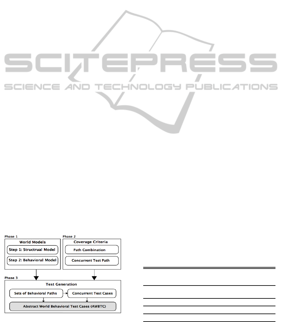
Figure 1: Behavioral Test Generation Process.
we construct a structural model of actors to repre-
sent their attributes, functions and relations. Second,
we construct the behavioral model to describe ac-
tors’ states and transitions and their interactions. Each
actor is presented by one behavioral model show-
ing messages they can send/receive. The commu-
nication between these actors represents the world
model. These communications need to be modeled
by a communicating behavioral semantic model such
as a CEFSM that handles the communication between
the actors. As such in our application (AGV and high-
way), actors are interacting simultaneously, the com-
municating behavioral model should cover not only
the internal transitions of actors, but also the commu-
nicating between them. The communicating behav-
ioral model can then be leveraged to generate world
behavioral test cases. Once we build the world behav-
ioral model, any member of the graph-based testing
criteria from (Ammann and Offutt, 2008) can be used
to generate behavioral test paths, which are abstract
world behavioral test cases (AWBTCs). The test gen-
eration process is illustrated in Figure 1. The world
model-based test generation process has the follow-
ing three phases:
• Model the world by constructing structural and
behavioral models.
• Select proper graph-based test criteria to cover the
communicating behavioral model.
• Generate AWBTCs which are test paths extracted
from the communicating behavioral model based
on selected criteria.
4.1 Phase 1: World Modeling
4.1.1 Structural Model
The structural model is constructed using a UML
class diagram, where classes represent actors includ-
ing their important characteristics, messages, and re-
lationships. Each group of actors is aggregated into
a single snippet. The number of involved actors in
the snippet is determined by their multiplicity rela-
tionship and similar actors that send common mes-
Table 1: Highway snippets instances.
Class vs-
pace0.08cm
Snippet Instances
Roadway Freeway, expressway, non-toll highway, toll
highway, and toll plaza.
Ramp
Entrance, exit, and switch ramp.
Bridge Movable/unmoveable bridges and tunnels.
Intersection Three, four, and five way of intersections.
TowardsWorldModel-basedTestGenerationinAutonomousSystems
169
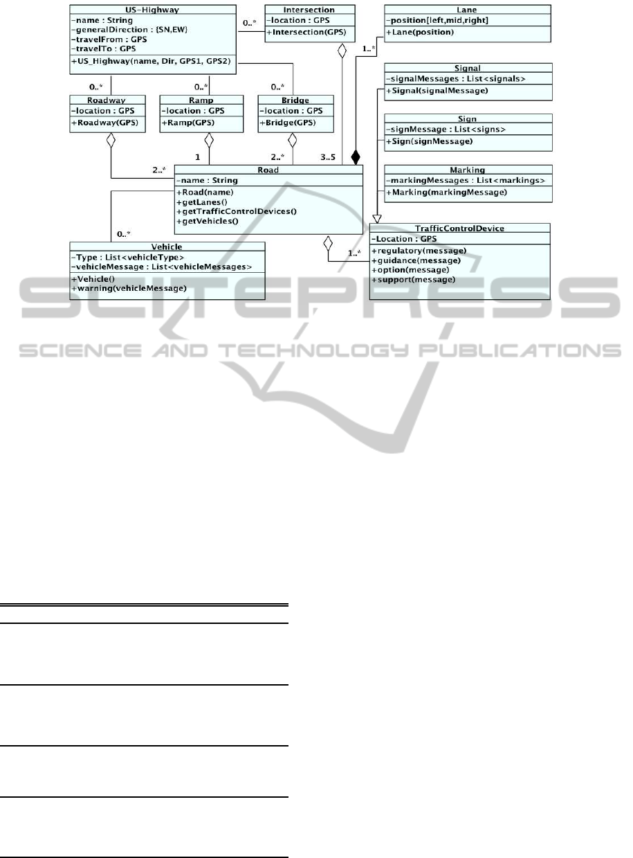
Figure 2: Structural Model for Highway Actors.
sages are generalized into a single class. The associ-
ation relation is also used to describe that one actor
can support or be part of another actor or snippet. In
our application, the highway can be represented by
four types of snippets, roadways, ramps, bridges, and
intersections. Table 1 shows examples of highway
snippet instances. Actors that are considered with a
highway are of four types: vehicles, signals, signs,
and markings traffic devices. For simplicity, at this
point, we assume that pedestrians do not exist in the
highway world. Actors’ instances and messages they
can send are illustrated in Table 2. The UML class di-
agram that represents the structural model of the high-
way world is shown in Figure 2.
Table 2: Highway actors instances.
Class
Actor Instances Messages
Vehicle
Passenger vehicles, fire
vehicles, law enforce-
ment vehicles, ambu-
lances, and other official
emergency vehicles.
ambulance.warning(
’turn flash light’).
fireTruck.warning(
’siren released’).
Signal
Traffic
Device
(Red and green), (Red,
yellow, and green) traf-
fic light, steady, flashing
arrows, No U-turn move-
ment flashing.
redGreenTLD.regluto-
ry(’redlight’). green-
Flashing Arrow.
guidance (’turn is
allowed’).
Sign
Traffic
Device
Stop, yield, speed limit,
fines double, do not pass,
emergency stopping only.
speedLimit.regulatory
(’speed limit 45’).
doNotPass.regulatory(
’Do Not Pass’).
Marking
Traffic
Device
White left-turn arrows,
single dotted and solid
white line, double solid
white and yellow lines,
lanes reduction.
laneReduction.regulat-
ory(’lanes reduction
single white line’).
4.1.2 Behavioral Model
Although a wide range of behavioral models exists,
we illustrate the behavioral model using communi-
cating extend finite state machines (CEFSMs). The
strength of CEFSM is that it can model orthogonal
states of a system in a flat manner and does not need
to compose the whole system in one state as in state
charts, which would make it more complicated and
harder to analyze and/or test (Brand and Zafiropulo,
1983; Li and Wong, 2002). CEFSM = (S, s
0
, E, P,
T, A, M, V, C), such that: S is a finite set of states,
s
0
is the initial state, E is a set of events, P is a set
of boolean predicates, T is a set of transition func-
tions such that T: S×P×E→S×A×M, A is a set of
actions, M is a set of communicating messages, V is
a set of variables, and C is the set of input/output
communication channels used in the CEFSM. State
changes (action language): The function T returns a
next state, a set of output signals, and an action list for
each combination of a current state, an input signal,
and a predicate. It is defined as: T(s
i
, p
i
, get(m
i
))/(s
j
,
A, send(m
j
1
,..., m
j
k
)) where, s
i
is the current state, s
j
is the next state, p
i
is the predicate that must be true
in order to execute the transition, e
i
is the event that
when combined with a predicate triggers the transi-
tion function, m
i
1
,..., m
i
k
are the messages. CEFSM is
a generalization of an EFSM (Cheng and Krishnaku-
mar, 1993) (i.e., adding communication channels be-
tween EFSMs). We model individual actors as EF-
SMs and their interaction as CEFSM. Table 3 shows
a set of EFSMs that represent a group of highway ac-
tors. Predicates that control transitions are also ex-
MODELSWARD2015-3rdInternationalConferenceonModel-DrivenEngineeringandSoftwareDevelopment
170
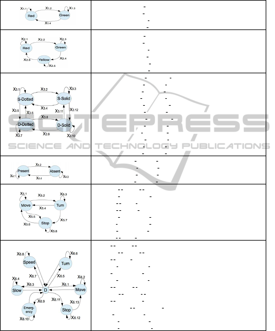
Table 3: Highway Actors’ Behavioral Models.
X1. Red & Green traffic light
X
1.1
:(Red,[timer<30sec], )/(Red,timer++,actor.regulatory(’Red light’))
X
1.2
:(Red,[timer=30sec], )/(Green,timer=0,actor.regulatory(’Green light’))
X
1.3
:(Green,[timer<30sec],
)/(Green,timer++,actor.regulatory(’Green light’))
X
1.4
:(Green,[timer=30sec], )/(Red,timer=0,actor.regulatory(’Red light’))
X2. Red, Green & Yellow traffic light
X
2.1
:(Red,[timer<60sec], )/(Red,timer++,actor.regulatory(’Red light’))
X
2.2
:(Red,[timer=60sec],
)/(Green,timer=0,actor.regulatory(’Green light’))
X
2.3
:(Green,[timer<60sec], )/(Green,timer++,actor.regulatory(’Green light’))
X
2.4
:(Green,[timer=60sec],
)/(Yellow,timer=0,actor.regulatory(’Yellow light’))
X
2.5
:(Yellow,[timer<30sec], )/(Yellow,timer++,actor.regulatory(’Yellow light’))
X
2.6
:(Yellow,[timer=30sec],
)/(Red,timer=0,actor.regulatory(’Red light’))
X3. Dotted and Solids Marking Devices
X
3.1
:(S-Dotted,[!Change], )/(S-Dotted, ,actor.regulatory(’Single dotted white line’))
X
3.2
:(S-Dotted,[Change], )/(S-Solid, ,actor.regulatory(’Single solid white line’))
X
3.3
:(S-Solid,[!Change],
)/(S-Solid, ,actor.regulatory(’Single solid white line’))
X
3.4
:(S-Solid,[Change], )/(S-Dotted, ,actor.regulatory(’Single dotted white line’))
X
3.5
:(S-Dotted,[Change],
)/(D-Dotted, ,actor.regulatory(’Double dotted white lines’))
X
3.6
:(D-Dotted,[Change], )/(S-Solid, ,actor.regulatory(’Single solid white line’))
X
3.7
:(D-Dotted,[!Change],
)/(D-Dotted, ,actor.regulatory(’Double dotted white lines’))
X
3.8
:(D-Dotted,[Change], )/(D-Solid, ,actor.regulatory(’Double solid white lines’))
X
3.9
:(D-Solid,[Change],
)/(D-Dotted, ,actor.regulatory(’Double dotted white lines’))
X
3.10
:(D-Solid,[!Change], )/(D-Solid, ,actor.regulatory(’Double solid white lines’))
X
3.10
:(D-Solid,[Change],
)/(S-Solid, ,actor.regulatory(’Single solid white line’))
X
3.12
:(S-Solid,[Change], )/(D-Solid, ,actor.regulatory(’Double solid white lines’))
X4. Traffic sign
X
4.1
:(Present,[Seen], )/(Present, ,actor.regulatory(’Traffic sign’s rule’))
X
4.2
:(Present,[!Seen],
)/(Absent, ,actor.regulatory(’Start traffic sign’s rule’))
X
4.3
:(Absent,[!Seen], )/(Absent, ,actor.regulatory(’Keep following rule’))
X
4.4
:(Absent,[Seen],
)/(Present, ,actor.regulatory(’New traffic sign’s rule’))
X5. Passenger Car
X
5.1
:(Move, , )/(Move, , )
X
5.2
:(Move, ,get(m
i
))/(Turn, ,actor.regulatory(’Turning flash light on’))
X
5.3
:(Turn,
, )/(Turn, ,actor.regulatory(’Turning flash light on’))
X
5.4
:(Turn, , )/(Move, ,actor.regulatory(’Turning flash light off’))
X
5.5
:(Move,
,get(m
i
))/(Stop, ,actor.regulatory(’Stop light on’))
X
5.6
:(Stop, ,get(m
i
))/(Move, ,actor.regulatory(’Stop light off’))
X
5.7
:(Turn,
,get(m
i
))/(Stop, ,actor.regulatory(’Stop light on’))
X
5.8
:(Stop, , )/(Stop, ,actor.regulatory(’Stop light on’))
X6. Car In an Emergency Situation
X
6.1
:(D, , )/(Move, , )
X
6.2
:(Move,
, )/(Move, , )
X
6.3
:(D, , )/(Slow, ,actor.regulatory(’Stop light on’))
X
6.4
:(Slow,
,get(m
i
))/(Slow, ,actor.regulatory(’Stop light on’))
X
6.5
:(D, ,get(m
i
))/(Turn, ,actor.regulatory(’Turning flash light on’))
X
6.6
:(Turn,
,get(m
i
))/(Turn, ,actor.regulatory(’Turning flash light’))
X
6.7
:(D, , )/(Speed, , )
X
6.8
:(Speed,
, )/(Speed, , )
X
6.9
:(D, , )/(Emergency, ,actor.regulatory(’Siren/Emergency-flashing’))
X
6.10
:(Emergency,
, )/(Emergency, ,actor.regulatory(’Siren/Emergency-flashing’))
X
6.11
:(D, ,get(m
i
))/(Stop, ,actor.regulatory(’Stop light’))
X
6.12
:(Stop,
,get(m
i
))/(Stop, ,actor.regulatory(’Stop light’))
X
6.13
:(Stop, ,get(m
i
))/(Move, ,actor.regulatory(’Stop light off’))
pressed in Table 3. Highway actors are a red-yellow-
green traffic light, a dotted-line marking device, a
speed-limit sign device, an ambulance,..., a passen-
ger car,..., etc. Note that X6 (Car in an emergency
situation) uses a dynamic node D to model commu-
nication between the various states. This is done to
reduce the number of transitions. Without it the graph
would be fully connected. This approach also uses
TowardsWorldModel-basedTestGenerationinAutonomousSystems
171

dummy edges without transition annotations as input
to node D. In our application, we selected the entrance
ramp snippet as an example. We also selected five ac-
tors (red-green traffic light, dotted-solid lines, speed
limit traffic sign, passenger vehicle, and emergent ve-
hicle) to participate in this snippet. Three of them,
the red-green traffic light, the dotted-solid lines, and
the traffic sign, do not receive messages from outside.
They only send messages periodically. The other two
actors, passenger and emergency vehicles, however,
do react to the messages that other actors send. They
also send and react to each other. For instance, when
the red-green traffic light actor turns to red, it sends a
message to all vehicles to stop but this traffic light ac-
tor does not react to any message that comes from the
world. On the other hand, a vehicle actor must stop
when it receives a red light message from the traffic
light actor. Figure 3 shows the CEFSM model that
represents the concurrent interactions between these
five actors over the entrance ramp snippet.
4.2 Phase 2: Coverage Criteria
Since actors interact concurrently, world behavioral
model can be defined as a collection of concurrent
processes. Each process is modeled as aCEFSM
i
that
can be represented as a directed graph G
i
= (N
i
, E
i
)
where N
i
is a set of nodes and E
i
is a set of edges and is
considered as a conventional graph where it is treated
sequentially (Yang and Chung, 1990). Test crite-
ria such as edge-coverage, prime-path coverage etc.
(Ammann and Offutt, 2008), can be applied. Using
any of a number of test path generation techniques,
test paths then can be generated that fulfill these cov-
erage criteria. Let P
i
= (p
i1
, p
i2
, ..., p
ik
) be a set of
such paths that cover G
i
, where 1 ≤ i ≤ |CEFSMs|
and |CEFSMs| is the number of CEFSMs, which
also corresponds to the number of actors that share
a snippet, and k is the number of paths that inter-
nally cover G
i
. We used edge-coverage to generate
internal paths that cover actors’ behavioral models
(X1, X2, ..., X6) from Table 3. The generated internal
path sets, P
1
, P
2
, ..., P
6
, are shown in the left column
of Table 4. These actor CEFSMs communicate via
the exchange of messages. There are two different
types of paths, internal and global paths, that repre-
sent the concurrent execution behavior of CEFSMs.
The internal paths describe the internal execution of
the processes that can be characterized by the input
and the sequence of the states involved in the execu-
tion. The global paths represent the communications
between the CEFSMs. The behavior varies depend-
ing on changes in synchronization conditions among
the concurrent processes. Therefore, the global paths
are considered concurrent paths. The concurrent in-
teraction between different paths that represent mul-
tiple CEFSMs produces an arbitrary combination of
internal paths of CEFSMs. As a result, we have two
types of coverage criteria, path combination and con-
current test path coverage criteria.
4.2.1 Path Combination Coverage Criteria
As mentioned earlier, each actor is represented as a
CEFSM. These CEFSMs communicate concurrently
via global messages which are seen as global paths,
as shown in the behavioral world model (High-level),
in Figure 3. Therefore, we first have to generate
global test paths that cover the global messages. We
used simple-path coverage, see (Ammann and Of-
futt, 2008), to generate global test paths that cover
the top level of the world behavioral model. Fig-
ure 3 shows six simple paths, SP
1
, SP
2
, . . . , SP
6
, that
cover the top level of the world model of the entrance
ramp snippet. Let WBM be defined as the set of sim-
ple paths {SP
1
, SP
2
, . . . , SP
m
}. Each simple path SP
i
is composed of multiple sets of {P
i
|1 ≤ i ≤ n, n is
the number of actors that participate in SP
i
} of in-
ternal paths, which actually represent a behavioral
scenario that can occur over the snippet. As a re-
sult, we have to combine each internal path p
1i
(a
path in P
1
) with other internal paths, p
5j
(a path in
P
5
) and p
6i
(a path in P
6
), in order to cover all possi-
ble combinations of internal paths that SP
1
can han-
dle. We use the same process for the other sim-
ple paths. Therefore, path combination coverage
criteria should determine what combinations are re-
quired. Let P
1
, P
2
, . . . , P
n
be a path through the be-
havioral world model WBM and the sets of internal
paths (nodes in SP
1
), P
1
= {p
11
,p
12
,.. .,p
1i
} and P
2
=
{p
21
,p
22
,.. .,p
2j
}. Then, the selection of p
1i
from P
1
and a p
2j
from P
2
is called a path combination. Let
len(p) be the number of nodes in path p, the length
of p. The path combination set of a simple path SP
i
,
Comb
SP
i
= {(p
jk
,.. .,p
mn
)|p
mn
∈ P
m
, m = len(SP
i
), n =
|P
i
|, 1 ≤ j ≤ m, 1 ≤ k ≤ n}. The number of all path
combinations of SP
i
will be the product of the number
of internal paths of each P
i
. Then, |Comb
SP
i
|=
len(SP
i
)
∏
j=1
|P
j
|.
At this point, we cover all possible combinations of
internal paths that a simple path SP
i
is composed of,
although not all of them are feasible due to lack of
reachability (Lei and Carver, 2006). Nevertheless,
the resulting set of path combinations are not yet test
paths, only path combinations that represent the ref-
erences to internal paths of various CEFSMs. There-
fore, we need test path coverage criteria that process
each path combination individually in order to gener-
ate concurrent test paths.
MODELSWARD2015-3rdInternationalConferenceonModel-DrivenEngineeringandSoftwareDevelopment
172
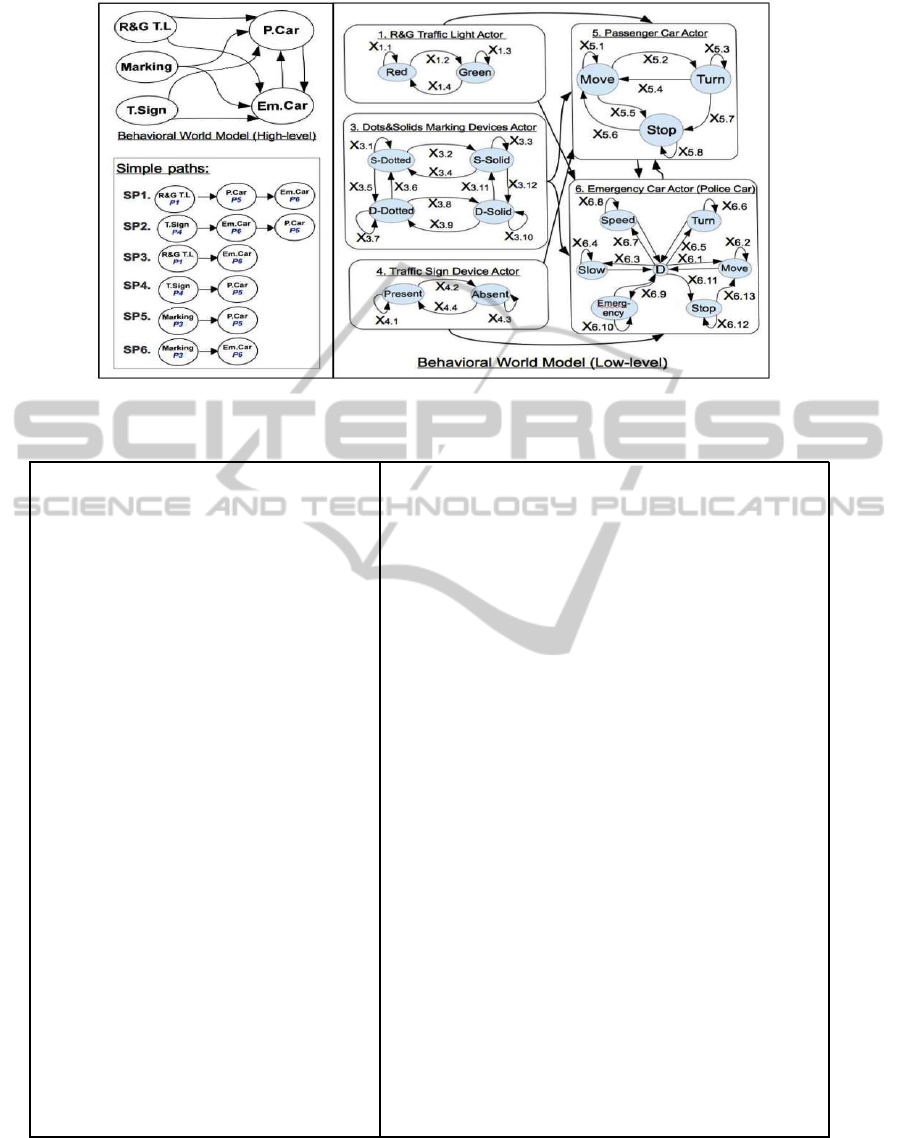
Figure 3: World Behavioral Model for Highway Entrance Ramp Snippet.
Table 4: Internal Paths of CEFSMs (using Edge Coverage) and Examples of AWBTCs.
P
1
is set of paths that covers X1:
p
11
: Red
X
1.1
−−→Red
X
1.2
−−→Green
p
12
: Green
X
1.3
−−→Green
X
1.4
−−→Red
P
3
is set of paths that covers X3:
p
31
: S-Dotted
X
3.2
−−→S-Solid
X
3.4
−−→S-Dotted
p
32
: S-Dotted
X
3.5
−−→D-Dotted
X
3.6
−−→S-Dotted
p
33
: D-Solid
X
3.9
−−→D-Dotted
X
3.8
−−→D-Solid
p
34
: S-Solid
X
3.12
−−−→D-Solid
X
3.11
−−−→S-Solid
P
4
is set of paths that covers X4:
p
41
: Present
X
4.2
−−→Absent
p
42
: Absent
X
4.4
−−→Present
P
5
is set of paths that covers X5:
p
51
: Move
X
5.2
−−→Turn
p
52
: Turn
X
5.3
−−→Turn
X
5.4
−−→Move
p
53
: Move
X
5.5
−−→Stop
p
54
: Turn
X
5.7
−−→Stop
p
55
: Stop
X
5.8
−−→Stop
X
5.6
−−→Move
P
6
is set of paths that covers X6:
p
61
: Slow
X
6.4
−−→Slow
X
6.11
−−−→Stop
p
62
: Stop
X
6.12
−−−→Stop
X
6.13
−−−→Move
p
63
: Move
X
6.5
−−→Turn
X
6.6
−−→Turn
p
64
: Move
X
6.7
−−→Speed
X
6.8
−−→Speed
p
65
: Move
X
6.9
−−→Emergency
X
6.10
−−−→Emergency
p
66
: Speed
X
6.3
−−→Slow
X
6.1
−−→Move
Example of path combinations and concurrent test paths that
represent simple paths, shown in Figure 3:
• Simple path SP1, where P
1
, P
5
and P
6
are synchronized:
- Combination c
11
=(p
11
, p
51
, p
61
)
p
11
[Red
X
1.1
−−→Red
X
1.2
−−→Green]
k
−→p
51
[Move
X
5.2
−−→Turn]
k
−→
p
61
[Slow
X
6.4
−−→Slow
X
6.11
−−−→Stop]
- Combination c
12
=(p
11
, p
51
, p
62
)
p
11
[Red
X
1.1
−−→Red
X
1.2
−−→Green]
k
−→p
51
[Move
X
5.2
−−→Turn]
k
−→
p
62
[Stop
X
6.12
−−−→Stop
X
6.13
−−−→Move]
• Simple path SP2, where P
4
, P
6
and P
5
are synchronized:
- Combination c
21
=(p
41
, p
61
, p
51
)
p
41
[Present
X
4.2
−−→Absent]
k
−→p
61
[Slow
X
6.4
−−→Slow
X
6.11
−−−→Stop]
k
−→
p
51
[Move
X
5.2
−−→Turn]
- Combination c
22
=(p
41
, p
61
, p
52
)
p
41
[Present
X
4.2
−−→Absent]
k
−→p
61
[Slow
X
6.4
−−→Slow
X
6.11
−−−→Stop]
k
−→
p
52
[Turn
X
5.3
−−→Turn
X
5.4
−−→Move]
• Simple path SP3, where P
1
and P
6
are synchronized:
- Combination c
31
=(p
11
, p
61
)
p
11
[Red
X
1.1
−−→Red
X
1.2
−−→Green]
k
−→p
61
[Slow
X
6.4
−−→Slow
X
6.11
−−−→Stop]
- Combination c
32
=(p
11
, p
62
)
p
11
[Red
X
1.1
−−→Red
X
1.2
−−→Green]
k
−→p
62
[Stop
X
6.12
−−−→Stop
X
6.13
−−−→Move]
• Simple path SP4, where P
4
and P
5
are synchronized:
- Combination c
41
=(p
41
, p
51
)
p
41
[Present
X
4.2
−−→Absent]
k
−→p
51
[Move
X
5.2
−−→Turn]
- Combination c
42
=(p
41
, p
52
)
p
41
[Present
X
4.2
−−→Absent]
k
−→p
52
[Turn
X
5.3
−−→Turn
X
5.4
−−→Move]
4.2.2 Concurrent Test Path Coverage Criteria
The produced path combination sets do not show how
these paths interact concurrently. Consequently, we
have to have concurrent test path coverage criteria.
In this paper, we investigate all possible serialized
execution sequences that a combination of paths can
produce although we expect that not all of these seri-
TowardsWorldModel-basedTestGenerationinAutonomousSystems
173

alizations are feasible. We also use the Rendezvous
technique, as in (Yang and Chung, 1990). These
concurrent test path coverage criteria are defined as
follows:
• All Possible Serialized ExecutionSequences Cov-
erage Criterion (APSESCC): Test requirements
contains a set of all possible serialized nodes of
the paths that are included in each path combina-
tion, i.e. each node in path p
ij
can be triggered by
each node in path p
kl
and vice versa. For example,
let p
ij
be a→b and p
kl
be x→y, where p
ij
and p
kl
are
in the same path combination, and a→b means a
sends a global message to b. Then, all serialized
executionsequences of path combinations (p
ij
,p
kl
)
will be: ((a→b→x→y),(a→x→b→y),(a→x→y→b),
(x→y→a→b), (x→a→y→b),(x→a→b→y)) .
If a path combination includes two paths and each
one contains three nodes, there are 20 possible se-
rializations. In general, all possible number of se-
rializations of nodes is
|Comb
SP
i
|
∑
i=1
(
(
len(c
ij
)
∑
j=1
|
p
mn
|
)!
len(c
ij
)
∑
j=1
(
|
p
mn
|
)!
).
We do not consider this a practicable criterion,
rather we can use it as an upper bound.
• Rendezvous Coverage Criterion (RCC): The test
requirements contain a set of all paths that have
rendezvous nodes. Then the possible number of
rendezvous-paths RZV of the simple path SP
i
is
n
∏
j=1
(P
j
+ 1) − 1.
4.3 Phase 3: Test Generation
Common algorithms that satisfy conventional test
coverage criteria stated in (Ammann and Offutt,
2008) are used. Our case study uses edge coverage
to generate the internal test paths for each CEFSM.
These test paths are then combined according to the
simple path coverage criterion to cover the high level
behavioral model. An example of internal test paths
is shown in the left column of Table 4. The test paths
in the right column of the same table are the com-
binations of the internal test paths that represent the
Table 5: Number of Path Combinations.
Simple Path
#Path Combination Sets
SP
1
→ (P
1
, P
5
, P
6
) = 2× 5× 6 = 60
SP
2
→ (P
4
, P
6
, P
5
) = 2× 6× 5 = 60
SP
3
→
(P
1
, P
6
) = 2× 6 = 12
SP
4
→
(P
4
, P
5
) = 2× 5 = 10
SP
5
→
(P
3
, P
5
) = 4× 5 = 20
SP
6
→
(P
3
, P
6
) = 4× 6 = 24
concurrent processes. We used the serialization algo-
rithm in (Yang and Chung, 1990) to generate these
concurrent paths. The concurrent paths illustrated in
the right column are serialized nodes of the internal
paths. We expressed the concurrency of the paths us-
ing double-bar ”||” as used in LOTOS for defining
concurrent functions, see (Sighireanu et al., 2000).
However, the generated test paths are still abstract. To
make these test paths executable, test-data coverage
criteria, i.e. input-space partitioning (Ammann and
Offutt, 2008), should be defined. One can also use the
input selection method defined in (Ran et al., 2009).
The number of concurrent behavioral test paths de-
pends on the coverage criteria chosen to combine and
generate test paths. The criteria used in this exam-
ple produced a huge number of AWBTCs, which is
expensive and requires reachability analysis (Carver
and Lei, 2013; Hwang et al., 1994; Yang and Chung,
1990) of the test paths. Table 5 shows the number of
combinations for each simple path SP
i
(i = 1. . . 6).
When we impose the All Serialized Execution Se-
quences Coverage Criterion (APSECC) on the path
combination set Comb
SP
i
, the number of produced
concurrent test paths increases exponentially. For in-
stance, the first path combination of Comb
SP
1
, as seen
in Table 4, c
11
=(p
11
, p
51
, p
61
), produced
(3+2+3)!
3!×2!×3!
= 560
test paths. The total number of AWBTCs generated
fromComb
SP
1
is 60480 test paths, and the whole num-
ber of AWBTCs generated from all path combina-
tion sets, Comb
SP
1
,Comb
SP
2
, . . . ,Comb
SP
6
, is 241920
test paths. This is clearly not scaleable. The Ren-
dezvous Coverage Criterion (RCC) on SP
1
results in
125 test paths as (((2+1) × (5+ 1) × (6+ 1)) − 1). Table 6
shows the number of test paths for each simple path
SP
i
(i = 1. . . 6). The total number of test paths gen-
erated from simple paths, SP
1
, SP
1
, . . . , SP
6
is 350 test
paths. This number of test paths is reasonable due to
the complexity of AGV systems.
5 CONCLUSION
This paper presented a novel model-based test gen-
eration approach that allows testing of autonomous
Table 6: Number of Test Paths for RCC.
Simple Path
#Test Paths
SP
1
→
(P
1
, P
5
, P
6
) = (((2+ 1)× (5+1) ×(6+1)) −1)= 125
SP
2
→
(P
4
, P
6
, P
5
) = (((2+ 1) × (6+ 1) × (5+ 1)) − 1) = 125
SP
3
→
(P
1
, P
6
) = (((2+ 1) × (6+ 1)) − 1) = 20
SP
4
→
(P
4
, P
5
) = (((2+ 1) × (5+ 1)) − 1) = 17
SP
5
→
(P
3
, P
5
) = (((4+ 1) × (5+ 1)) − 1) = 29
SP
6
→
(P
3
, P
6
) = (((4+ 1) × (6+ 1)) − 1) = 34
MODELSWARD2015-3rdInternationalConferenceonModel-DrivenEngineeringandSoftwareDevelopment
174

systems in their dynamic world. We modeled an ac-
tive world of an autonomous system. A test genera-
tion process is defined. In addition, a path combina-
tion technique is introduced and formalized in order
to generate concurrent test paths (AWBTCs). Two
concurrent test criteria (APSESCC and RCC) are in-
vestigated. The findings indicate that RCC is practi-
cally feasible. Reachability analysis (Carver and Lei,
2013; Hwang et al., 1994; Yang and Chung, 1990)
is required for both criteria (APSESCC and RCC) to
increase their feasibility and efficiency. Future work
will explore other path combination and concurrent
test path coverage criteria. Future work will also ex-
periment using the CADP (Construction and Analy-
sis of Distributed Processes) toolbox (Garavel et al.,
2013). Reachability analysis investigations and scala-
bility of the world behavioral model will also be pro-
vided. We also plan on extending the approach to
other robotic systems such as robots interacting with
humans in manufacturing.
ACKNOWLEDGEMENTS
This work was supported, in part, by NSF IUCRC
grant # 0934413, 1127947, and 1332078 to the Uni-
versity of Denver.
REFERENCES
Ammann, P. and Offutt, J. (2008). Introduction to Software
Testing. Cambridge University Press, 32 Avenue of
the Americas, New York, NY 10013, USA, first edi-
tion.
Andrews, A., Offutt, J., Dyreson, C., Mallery, C. J., Jerath,
K., and Alexander, R. (2010). Scalability issues with
using fsmweb to test web applications. Inf. Softw.
Technol., 52(1):52–66.
Arnold, J. and Alexander, R. (2013). Testing autonomous
robot control software using procedural content gen-
eration. In Bitsch, F., Guiochet, J., and Kaniche, M.,
editors, Computer Safety, Reliability, and Security,
volume 8153 of Lecture Notes in Computer Science,
pages 33–44. Springer Berlin Heidelberg.
Brand, D. and Zafiropulo, P. (1983). On communicating
finite-state machines. J. ACM, 30(2):323–342.
Carver, R. and Lei, Y. (2013). A modular approach
to model-based testing of concurrent programs. In
Lourenco, J. and Farchi, E., editors, Multicore Soft-
ware Engineering, Performance, and Tools, volume
8063 of Lecture Notes in Computer Science, pages
85–96. Springer Berlin Heidelberg.
Cheng, H. (2011). Autonomous Intelligent Vehicles: The-
ory, Algorithms, and Implementation. Springer-
Verlag, Springer London Dordrecht Heidelberg, New
York, first edition.
Cheng, K. T. and Krishnakumar, A. (1993). Automatic
functional test generation using the extended finite
state machine model. In Proceedings of the 30th In-
ternational Design Automation Conference, DAC ’93,
pages 86–91, New York, NY, USA. ACM.
Couceiro, M., Vargas, P., Rocha, R., and Ferreira, N. (2014).
Benchmark of swarm robotics distributed techniques
in a search task. Robotics and Autonomous Systems,
62(2):200–213.
Dias-Neto, A., Subramanyan, R., Vieira, M., and Travas-
sos, G. H. (2007). A survey on model-based test-
ing approaches: A systematic review. In Proceedings
of the 1st ACM International Workshop on Empiri-
cal Assessment of Software Engineering Languages
and Technologies: Held in Conjunction with the
22Nd IEEE/ACM International Conference on Auto-
mated Software Engineering (ASE) 2007, WEASEL-
Tech ’07, pages 31–36. ACM.
Fisher, M., Dennis, L., and Webster, M. (2013). Verifying
autonomous systems. Commun. ACM, 56(9):84–93.
Furda, A. and Vlacic, L. (2010). An object-oriented de-
sign of a world model for autonomous city vehicles.
In Intelligent Vehicles Symposium (IV), IEEE, pages
1054–1059.
Garavel, H., Lang, F., Mateescu, R., and Serwe, W. (2013).
Cadp 2011: a toolbox for the construction and anal-
ysis of distributed processes. International Journal
on Software Tools for Technology Transfer, 15(2):89–
107.
Ghete, I., Heizmann, M., Belkin, A., and Beyerer, J. (2010).
World modeling for autonomous systems. In Dill-
mann, R., Beyerer, J., Hanebeck, U., and Schultz, T.,
editors, KI 2010: Advances in Artificial Intelligence,
volume 6359 of Lecture Notes in Computer Science,
pages 176–183. Springer Berlin Heidelberg.
Hessel, A., Larsen, K., Mikucionis, M., Nielsen, B., Pet-
tersson, P., and Skou, A. (2008). Formal methods and
testing. chapter Testing real-time systems using UP-
PAAL, pages 77–117. Springer-Verlag, Berlin, Hei-
delberg.
Hwang, G.-H., Tai, K.-C., and Huang, T. (1994). Reachabil-
ity testing: an approach to testing concurrent software.
In Proceedings of the Software Engineering Confer-
ence, 1994 First Asia-Pacific, pages 246–255.
Iqbal, M., Arcuri, A., and Briand, L. (2012). Empiri-
cal investigation of search algorithms for environment
model-based testing of real-time embedded software.
In Proceedings of the 2012 International Symposium
on Software Testing and Analysis, ISSTA 2012, pages
199–209, New York, NY, USA. ACM.
Jacoff, A., Messina, E., Weiss, B., Tadokoro, S., and Naka-
gawa, Y. (2003). Test arenas and performance metrics
for urban search and rescue robots. In Proceedings
of the IEEE International Conference on Intelligent
Robots and Systems (IROS), volume 4, pages 3396–
3403 vol.3.
Lei, Y. and Carver, R. H. (2006). Reachability testing
of concurrent programs. IEEE Trans. Softw. Eng.,
32(6):382–403.
Li, J. and Wong, W. (2002). Automatic test generation
from communicating extended finite state machine
TowardsWorldModel-basedTestGenerationinAutonomousSystems
175

(CEFSM)-based models. In Proceedings of 5th IEEE
International Symposium on Object-Oriented Real-
Time Distributed Computing. (ISORC 2002), pages
181–185.
Lill, R. and Saglietti, F. (2012). Model-based testing of
autonomous systems based on coloured petri nets. In
ARCS Workshops (ARCS), pages 1–5.
Nguyen, C., Perini, A., Bernon, C., Pavon, J., and
Thangarajah, J. (2011). Testing in multi-agent sys-
tems. In Proceedings of the 10th International
Conference on Agent-oriented Software Engineer-
ing, AOSE’10, pages 180–190, Berlin, Heidelberg.
Springer-Verlag.
Ran, L., Dyreson, C., Andrews, A., Bryce, R., and Mallery,
C. (2009). Building test cases and oracles to automate
the testing of web database applications. Inf. Softw.
Technol., 51(2):460–477.
Rehman, S. and Nadeem, A. (2013). Testing of autonomous
agents: A critical analysis. In Proceedings of the 2013
Saudi International Electronics, Communications and
Photonics Conference (SIECPC), pages 1–5.
Shafique, M. and Labiche, Y. (2013). A systematic review
of state-based test tools. International Journal on Soft-
ware Tools for Technology Transfer, pages 1–18.
Shirole, M. and Kumar, R. (2013). Uml behavioral model
based test case generation: A survey. Softw. Eng.
Notes, SIGSOFT, 38(4):1–13.
Sighireanu, M., Chaudet, C., Garavel, H., Herbert, M., Ma-
teescu, R., and Vivien, B. (2000). Lotos nt user man-
ual.
Tretmans, J. (2008). Model based testing with labelled
transition systems. In Hierons, R., Bowen, J., and
Harman, M., editors, Formal Methods and Testing,
volume 4949 of Lecture Notes in Computer Science,
pages 1–38. Springer Berlin Heidelberg.
U.S. Department of Transportation, F. H. A. F. (2013). Man-
ual on uniform traffic control devices MUTCD.
Utting, M., Pretschner, A., and Legeard, B. (2012). A
taxonomy of model-based testing approaches. Softw.
Test. Verif. Reliab., 22(5):297–312.
Yang, R. and Chung, C.-G. (1990). A path analysis ap-
proach to concurrent program testing. In Proceedings
of the 9th Annual International Phoenix Conference
on Computers and Communications, pages 425–432.
Zander, J., Schieferdecker, I., and Mosterman, P. J. (2012).
Model-based testing for embedded systems. CRC
Press, 6000 Broken Sound Parkway NW,Boca Raton,
FL 3348, USA, first edition.
MODELSWARD2015-3rdInternationalConferenceonModel-DrivenEngineeringandSoftwareDevelopment
176
