
Novel DFT-based Channel Estimation Scheme
for Sidehaul System
Hun Choe, Sangmi Moon and Intae Hwang
Dept. of Electronics and Computer Engineering, Chonnam National University
300 Yongbongdong Bukgu Gwangju, 500-757, Republic of Korea
Keywords: 2-D MMSE, DFT-based Channel Estimation, DMRS, MIMO, SC-FDMA, Sidehaul System.
Abstract: Recently, 3rd Generation Partnership Project (3GPP) has developed sidehaul system to cope with the
explosively increasing mobile data traffic. The sidehaul system is based on single carrier-frequency division
multiple access (SC-FMDA) due to its low peak-to-average power ratio (PAPR). Also, demodulation
reference signal (DMRS) is designed to support multiple input multiple output (MIMO). In this paper, we
propose the DFT-based channel estimation scheme for sidehaul system. The proposed scheme uses the 2-
dimensional minimum mean square error (2-D MMSE) interpolation scheme for the user moving at a high
speed. Simulation results show that the proposed channel estimation scheme can improve normalized mean
square error (NMSE), error rate and throughput of conventional system.
1 INTRODUCTION
Explosive demands for mobile data communication
are driving changes in the way mobile operators
respond to the challenging requirements of higher
capacity and improved quality of user experience
(QoE). Currently, the 3rd Generation Partnership
Project (3GPP) has developed small cells by
increasing the node deployment density in
macrocells to handle increased capacity
requirements ((http://www. qualcomm.com/media/
documents / files / 1000x-more-smallcells-web-.pdf;
Hamalainen, 2012; Nakamura, 2012).
This approach, nevertheless, has a fundamental
problem in that the cost of operation and installation
increases with the number of small cells deployed.
Especially, the fixed small cell is inefficient in
environments where the maximum local traffic
changes by the hour owing to the increase in the
floating population.
To solve this problem, we need to develop a
moving small cell that can be connected to the
macro base station through a wireless backhaul
system, and is movable by the user. Nevertheless,
there is a limit to the network capacity that can be
increased only by wireless backhaul technologies.
As the network capacity is limited by the wireless
backhaul system that connects the macro base
station, a sidehaul system between moving small
cells is required to enable a moving small cell to
communicate.
In moving small-cell environments, inter-cell
interference increases. Studies have been carried out
to solve the interference problem by adopting a
transmission method to reduce the interference at the
base station, a cooperation technique between cells
(Myung et al., 2006; 3GPP, TS 36.211, 2013), and a
high-performance reception algorithm that handles
the interference at the receiver. In the former case,
each user equipment (UE) has to feed back the
channel information for the interference information
to be processed. In view of the possible inaccuracy
of the feedback information as well as the feedback
overhead due to the increase of the number of
antennas, there are restrictions on this interference
processing method that requires feedback.
Meanwhile, another interference processing method
at the receiver has recently attracted the attention in
3GPP as the method does not require feedback.
Network-assisted interference cancellation and
suppression (NAICS) is the technology used to
reduce the adverse effect of interference by using
interference cancellation receivers and interference
suppression receivers. In terms of improvement of
the capacity and interference cancellation, several
receiver algorithms based on the minimum mean-
square error (MMSE) have been proposed for multi-
195
Choe H., Moon S. and Hwang I..
Novel DFT-based Channel Estimation Scheme for Sidehaul System.
DOI: 10.5220/0005232001950201
In Proceedings of the 5th International Conference on Pervasive and Embedded Computing and Communication Systems (PECCS-2015), pages
195-201
ISBN: 978-989-758-084-0
Copyright
c
2015 SCITEPRESS (Science and Technology Publications, Lda.)
cell environments. 3GPP Release 12 selects NAICS
as the study item (SI) and discusses the
improvement in performance, the type of support
information, and the overhead with network support
(Zaka et al., 2009).
In this paper, we first describe the conventional
receiver used to reduce the inter-cell interference
and propose a hybrid receiver that integrates the
interference rejection combining (IRC) technique
with successive interference cancellation (SIC). The
paper is organized as follows. We present the
overview of the sidehaul system in Section 2.
Section 3 describes the conventional receivers. In
section 4, we propose the novel hybrid receiver for
achieving full successive cancellation (FSC).
Section 5 presents the performance analysis of the
proposed scheme through simulations. Finally, the
conclusion drawn is given in section 6.
2 STRUCTURE OF
TRANSMITTER AND
RECEIVER IN SIDEHAUL
SYSTEM
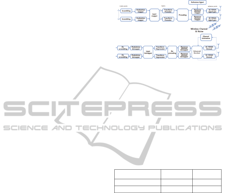
We design the structure of transmitter and receiver
in sidehaul system based on uplink of LTE-
Advanced (3GPP, TS 36.211, 2013). As depicted in
Figure 1, the baseband signal representing the
physical sidehaul shared channel (PSSCH) is
defined in terms of the following steps:
- Scrambling
- Modulation of scrambled bits to generate
complex-valued symbols
- Mapping of the complex-valued modulation
symbols onto one or several transmission layers
- Transform precoding to generate complex-
valued symbols
- Precoding of the complex-valued symbols
- Mapping of precoded complex-valued symbols
to resource elements
- Generation of complex-valued time-domain
SC-FDMA signal for each antenna port
After generating the PSSCH, the transmitter
sends them out through the wireless channel. The
received signal is usually distorted by the channel
characteristic. In order to recover the transmitted
signal, the channel is estimated using the reference
signal and compensated in receiver.
SC-FDMA has drawn great attention as an
attractive alternative to OFDMA, especially in the
uplink communications where lower PAPR greatly
benefits the mobile terminal in terms of transmit
Figure 1: Block diagram of transmitter and receiver in
sidehaul system.
power efficiency and reduced cost of the power
amplifier. Therefore, it has been adapted as the
access scheme in sidehaul system.
A physical resource block (PRB) is the minimal
unit for resource allocation in sidehaul system. A
PRB is defined as N_symb^UL consecutive SC-
FDMA symbols in the time domain and N_sc^RB
consecutive subcarriers in the frequency domain,
where N_symb^UL and N_sc^RB are given by
Table 1.
A PRB consists of N_symb^UL×N_sc^RB
resource elements, corresponding to one slot in the
time domain and 180 kHz in the frequency domain.
Table 1: Resource Block Parameters.
Configuration
Normal cyclic prefix 12 7
Extended cyclic prefix 12 6
Each radio frame is 10ms long and consists of 20
slots of length 0.5ms. A subframe is defined as two
consecutive slots where subframe i consists of slots
2i and 2i+1.
3 SIDEHAUL REFERENCE
SIGNAL DESIGN
PSSCH is the channel for sideaul data transmission,
and DMRS is reference to acquire the channel
estimation values used in the PSSCH data detection.
Different DMRS sequences are needed to support
the MIMO system. In this section, we describe the
DMRS structure.
3.1 DMRS Design
DMRS sequence is generated using the constant
amplitude zero auto correlation (CAZAC) sequence
PECCS2015-5thInternationalConferenceonPervasiveandEmbeddedComputingandCommunicationSystems
196

to separate the signal of each terminal with code
division multiplex (CDM) [5]. A DMRS sequence
is defined by a cyclic shift (CS) α of a base sequence
according to
RS
sc,
)(
,
0),()( Mnnrenr
vu
nj
vu
(1)
where is the length of DMRS sequence, m is the
PRB number and is the subcarrier number within
each PRB. Multiple DMRS sequence can be derived
from a single base sequence through different values
of α.
The definition of the base sequence depends on
the sequence length. For , the base sequence is
given by.
RS
sc
RS
ZC,
0),mod()( MnNnxnr
qvu
(2)
where the
th
q
root Zadoff-Chu sequence is defined
by
10,
RS
ZC
)1(
RS
ZC
Nmemx
N
mqm
j
q
(3)
with
q
given by
31)1(
)1(21
RS
ZC
2
uNq
vqq
q
(4)
The length
RS
ZC
N
of the Zadoff-Chu sequence is
given by the largest prime number such that
RS
sc
RS
ZC
MN
. For ,
RB
sc
RS
sc
3NM
base sequence is
defined as computer generated constant amplitude
zero autocorrelation (CG-CAZAC) sequence and is
given by
10,)(
RS
sc
4)(
,
Mnenr
nj
vu
(5)
where the value of
)(n
is given in (3GPP, TS
36.211, 2013).
In order to reduce the inter-cell interference (ICI),
there are two kinds of hopping defined for the
DMRS. First, group hopping is the method to obtain
an effect of randomizing of ICI by changing the
group index in slot unit. The sequence-group
number
u
in slot
s
n
is defined by a group hopping
pattern
)(
sgh
nf
and a sequence-shift pattern
according to
30mod)(
sssgh
fnfu
(6)
There are 17 different hopping patterns and 30
different sequence-shift patterns. The hopping
pattern is generated based on 17 random hopping
patterns. Thus group hopping pattern for 504 cell ID
is represented with combination of patterns.
Secondly, sequence hopping only applies for
reference-signals of length
RB
sc
RS
sc
6
NM
. Hopping
takes place between two base sequence indexes
within the base sequences group as slot unit in sub-
frame. For reference-signals of length
RB
sc
RS
sc
6
NM
, the base sequence number
v
within the base
sequence group is given by
0v
. For reference-
signals of length
RB
sc
RS
sc
6
NM
, the base sequence
number
v
within the base sequence group in slot
s
n
is defined by
otherwise0
enabled is hopping sequence and disabled is hopping group if)(
s
nc
v
(7)
where
)(
ic
is the pseudo-random sequence.
In order to support MIMO transmission in
sidehaul system, DMRS between the antennas are
orthogonal by using the CAZAC sequence with
different cyclic shift value each antenna. The
PSSCH demodulation reference signal sequence
∙ associated with transmit antenna,
0,1,⋯,
1, is defined by
̅
,
,0,⋯,
1
(8)
where cyclic shift
in a slot
s
n
is given as
2
,
/12 with
,
,
∙12
(9)
Therefore, it is possible to separate the channel by
orthogonal DMRS between the antennas.
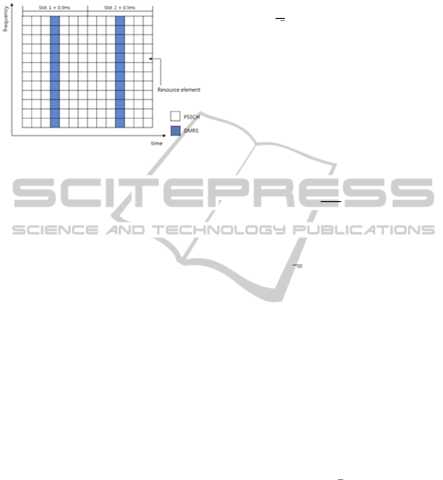
3.2 Mapping of DMRS
In sidehaul system, the DMRS for PSSCH in the
frequency domain will be mapped to the same set of
PRB used for the corresponding PSSCH
transmission with the same length expressed by the
number of subcarriers, while in the time domain
DMRS will occupy the 4th SC-FDMA symbol in
each slot with normal cyclic prefix (CP), as shown
in Figure 2. In case of extended CP, DMRS will
occupy the 3rd SC-FDMA symbol in each slot.
In this mapping, SC-FDMA symbols with
DMRS at all are transmitted periodically for channel
estimation. Using these DMRS, a time-domain
interpolation is performed to estimate the channel
along the time axis. Since DMRS are inserted into
all subcarriers of DMRS with a period in time, this
arrangement is suitable for frequency-selective
channels. For the fast-fading channels, however, it
might incur too much overhead to track the channel
variation by reducing the DMRS period. Therefore,
we will propose the channel estimation scheme for
NovelDFT-basedChannelEstimationSchemeforSidehaulSystem
197
the time-varying channel in the next section.
Figure 2: Mapping of DMRS.
4 NOVEL DFT-BASED CHANNEL
ESTIMATION SCHEME
In this section, we describe the DFT-based channel
estimation scheme and propose the 2-dimensional
minimum mean square error (2-D MMSE) to
compensate the effect of ICI in the time varying
channels.
4.1 Novel DFT-based Channel
Estimation
The received signal by the jth receive antenna in the
kth subcarrier and the lth SC-FDMA symbol,
,
, is expressed as follows
,
∑
,
,
,
,
, (10)
where
, represents
channel matrix
of the th subcarrier and the th SC-FDMA symbol,
, represents
-dimensional transmit signal
vector of the th subcarrier and the th SC-FDMA
symbol, and , is the
-dimensional additive
white gaussian noise (AWGN) vector.
Based on Figure 2, we can see that
,3
,10
, since group hopping and
sequence hopping are not assumed here, which are
the DMRS. The channel estimation is based on
,3
and
,10
.
The steps for DFT-based channel estimation are
as follows:
1) Multiply Y(k,3) with the conjugate of r_0 (k),
i.e.,
,3
,3
0
∗
(11)
2) Perform N-point IFFT over H ̃(k,3) to get the
time domain channel, i.e.,
,3
√
∑
,3
/
(12)
where 01.
3) Perform the windowing for channel impulse
response (CIR) using window function, i,e.,
,3
,3
,
0,
(13)
where window parameter
and
are the
number sample of positive region and negative
region of window function, respectively. And that
are set considering the delay spread and size of
channel.
4) Separate the time domain channel for different
data stream, i.e., calculate
,3
,
,3
(14)
5) Do N-point FFT of
,3
to get the
frequency domain channel response of each data
stream, i.e.,
,
,3
√
∑
,3
/
(15)
Find the channel frequency response by performing
the above process for the rest of ,10
4.2 Interpolation Scheme
To estimate the channel for data signal, the reference
signal subcarriers must be interpolated. Since
channel frequency responses from DFT-based
channel estimation are separated into 7 SC-FDMA
symbols.
4.2.1 Linear Interpolation
Linear interpolation is the simplest method for
interpolation. We calculate the linear equation using
channel frequency response that is obtained from the
DFT-based channel estimation [6].
,
,
,
,3
,
,10
,
,3
, 0,1,⋯, 1
(16)
Where 7 is the spacing between DMRS.
4.2.2 2-D MMSE Interpolation
Linear interpolation scheme may be applicable only
when the channel characteristic does not change
within an SC-FDMA symbol period. However, the
PECCS2015-5thInternationalConferenceonPervasiveandEmbeddedComputingandCommunicationSystems
198

channel for the terminals that move fast may vary
with time within an SC-FDMA symbol period, in
which longer SC-FDMA symbol period has a more
severe effect on the channel estimation performance.
The time-varying channel may destroy the
orthogonality among subcarriers at the receiver,
resulting in ICI. Due to the effect of ICI, it cannot be
compensated by the conventional interpolation
scheme.
In order to deal with the effect of ICI in the time-
varying channels, we propose the 2-D MMSE
interpolation that performs the interpolation in both
frequency and time domain. The following
algorithm summarizes how to get the estimates
.
First, we update the channel estimation about
SC-FDMA symbol including the DMRS signal in
frequency domain.
(17)
where
is expressed in (15).
Then we apply the MMSE in time domain and
estimate the channel impulse response for the entire
SC-FDMA symbols.
(18)
where
is the cross-correlation matrix between
the true channel and temporary channel estimate
and
autocorrelation matrix of temporary
channel estimate
5 SIMULATION RESULTS AND
PERFORMANCE ANALYSIS
In this section, we will present the simulation results
for proposed channel estimation scheme and
analysis the performance. The simulation results are
based on the link level Monte Carlo simulations.
Table 2 shows the general simulation parameters
and defines the simulated environment. Table 3,
shows the power delay profile (PDP) of extended
typical urban (ETU) channel. The simulation
parameters are based on 3GPP LTE-Advanced
system 20 MHz Bandwidth. And time variant
frequency selective channel is modeled according E-
UTRA ETU channel with maximum Doppler
frequency (
of 300Hz (3GPP TS 36.101, 2013).
Also in channel estimation, window parameters are
set
16 and
160 considering the
delay spread and size of ETU channel.
Table 2: Simulation parameters.
Parameter Value
Carrier frequency 2 GHz
Bandwidth 20 MHz
Sample frequency 30.72 MHz
Subframe duration 1 ms
Subcarrier spacing 15 kHz
FFT size 2048
Occupied subcarriers 1200
No. of subcarriers/PRB 12
Cyclic Prefix (CP) Normal CP
No. of OFDM
symbols/subframe
14 (Normal CP)
Channel Model ETU, fd = 300Hz
MIMO Configuration 4x4
Channel Estimation Ideal, 2-D MMSE, Linear
Advanced Receiver MMSE
Table 3: ETU Channel Model.
Excess tap delay
[ns]
Excess tap delay
[sample]
Relative power
[dB]
0 0 -1.0
50 2 -1.0
120 4 -1.0
200 6 0.0
230 7 0.0
500 15 0.0
1600 49 -3.0
2300 71 -5.0
5000 154 -7.0
Figure 3 shows the normalized mean square error
(NMSE) performance according to channel
estimation scheme. The proposed 2-D MMSE brings
performance improvements with 3 dB SNR as
NovelDFT-basedChannelEstimationSchemeforSidehaulSystem
199
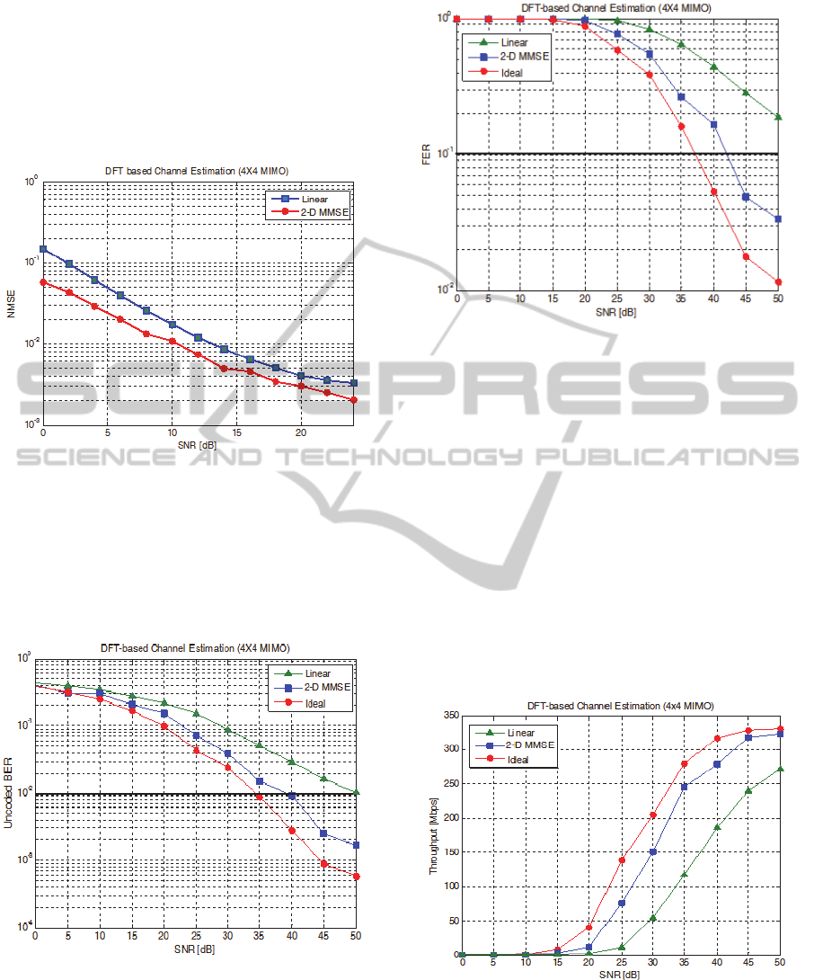
referenced to NMSE 10
compared to linear
interpolation. Because the proposed scheme
estimates the channel of SC-FDMA symbol not
including the DMRS using the correlation
characteristic of the channel except 3 and
10. Therefore, proposed scheme can estimate the
channel of moving small cells at high speed.
Figure 3: MMSE performance according to channel
estimation scheme.
Figure 4 shows the Uncoded bit error rate (BER)
according to channel estimation scheme. As
referenced to Uncoded BER 10
, 35 dB, 40 dB,
and 50 dB are the minimum required SNR of Ideal,
2-D MMSE and Linear, respectively.
Figure 4: BER performance according to channel
estimation scheme.
Figure 5 shows the frame error rate (FER) according
to channel estimation scheme. As referenced to FER
10
, 37 dB, 43 dB, and 55 dB are the minimum
required SNR of Ideal, 2-D MMSE and Linear,
respectively.
Figure 5: FER performance according to channel
estimation scheme.
From the simulation results as shown in figure 4 and
5, the proposed scheme bring the significant error
performance gain compared with linear interpolation
scheme.
Figure 6 shows the throughput performance
according to channel estimation scheme. The theory
maximum data rate is 334.31 Mbps considering the
DMRS and physical sidehaul control channel
(PSCCH). As referenced to SNR 50 dB, it can be
seen that Ideal, 2-D MMSE and Linear reach the 330
Mbps, 323 Mbps and 272 Mbps, respectively.
Therefore, the proposed scheme brings performance
improvements with 12 dB SNR as referenced to 250
Mbps compared to linear interpolation.
Figure 6: Throughput performance according to channel
estimation scheme.
PECCS2015-5thInternationalConferenceonPervasiveandEmbeddedComputingandCommunicationSystems
200

6 CONCLUSIONS
In this paper, we design DMRS to support the
MIMO transmission for high speed and capacity
data transmission in sidehaul system between
moving small cells. Also, we propose the DFT-based
channel estimation scheme. The proposed scheme
uses the 2-D MMSE interpolation scheme for the
user moving at a high speed. Simulation results
show that the proposed scheme brings performance
improvements with 3 dB SNR as referenced to
NMSE 10
compared to conventional scheme. In
case of error rate results, we observe that the
proposed scheme clearly outperforms the
conventional shcme, with considerable gain of 10
dB and 12 dB as referenced to Uncoded BER 10
and FER 10
, respectively. Therefore the proposal
in this study is a promising solution for channel
estimation in sidehaul system. In our future work,
the frame structure could be design to improve the
maximum data rate in sidehaul system.
ACKNOWLEDGEMENTS
This research was supported by Basic Science
Research Program through the National Research
Foundation of Korea(NRF) funded by the Ministry
of Education(NRF-2013R1A1A2007779).
REFERENCES
Qualcomm, “1000x: More Small Cells – Taking HetNets
to the Next Level,” (http://www.
qualcomm.com/media/documents/files/1000x-more-
smallcells-web-.pdf).
J. Hamalainen (Ericsson),2012. 2 “Towards
Heterogeneous Networks” (http://bnrg.cs.berkeley.edu
/~randy/Courses/CS294.S13/13.3.pdf).
T. Nakamura (NTT Docomo), 2012. “Further LTE
Enhancements toward Future Radio Access”.
H. G. Myung, J. Lim and D. J. Goodman, Sept. 2006.
“Single carrier FDMA for uplink wireless
transmission,” IEEE Veh, Techno. Ma.g., vol. 1, no. 3,
pp. 30-38.
3GPP, TS 36.211, Sept. 2013. “Evolved Universal
Terrestrial Radio Access (E-UTRA); Physical
channels and modulation,” V11.4.0.
Klodiana Zaka, Agha Yasir Ali, M. Irfan Anis, Shariq-uz-
Zaman, Irfan Usmani and Naveed Ahmed, , Nov. 2009.
“Technique for channel estimation in OFDM
transmission system using linear interpolation and
Euclidean distance algorithm,” Asian Himalayas
International Conference on Internet (AH-ICI) 2009, pp.
1-5.
3GPP TS 36.101, March 2013. “Evolved Universal
Terrestrial Radio Access (E-UTRA); User Equipment
(UE) radio transmission and reception,” V11.4.0.
NovelDFT-basedChannelEstimationSchemeforSidehaulSystem
201
