
A Toolset for Simulink
Improving Software Engineering Practices in Development with Simulink
Vera Pantelic, Steven Postma, Mark Lawford, Alexandre Korobkine, Bennett Mackenzie, Jeff Ong
and Marc Bender
McMaster Centre for Software Certification, Department of Computing and Software,
McMaster University, Hamilton, ON, Canada
Keywords:
Simulink, Tools, Software Engineering, Transformation, Data Flow.
Abstract:
This paper presents a set of tools that provide automatic support for application of some of the traditional soft-
ware engineering practices when developing with Simulink. The tools are the: Signature Tool, Reach/Coreach
Tool, Data Store Push-Down Tool, and Auto Layout Tool. The Signature Tool extracts the interface of a
Simulink subsystem, identifying the subsystem’s explicit, and implicit data flow mechanisms, empowering
developers to use the implicit mechanisms more effectively. The Reach/Coreach Tool identifies data and
control flow dependencies in a Simulink model and uses the information for model slicing. The view of de-
pendencies offered by the tool significantly eases the comprehension of large models. The dependencies can
also serve as indicators of alternative designs, and facilitate more effective testing and verification. The Data
Store Push-Down Tool restricts the scope of Simulink’s data stores thereby providing improved encapsulation,
and increasing modularity. Finally, the Auto Layout Tool significantly decreases the manual effort develop-
ers spend in achieving proper layout of models during design and refactoring, and can be used by automated
refactoring and transformation tools.
1 INTRODUCTION
The use of MATLAB/Simulink as a model-based de-
sign environment is wide spread across industries.
While there are a number of reasons for its popularity
(e.g., automatic code generation, rich modeling and
simulation capabilities, existence of a large number
of MathWorks and third party tools to aid develop-
ment within the environment), the environment still
lacks proper support for the application of some tra-
ditional software engineering practices. For example,
Simulink does not have facilities to provide for data
stores
1
to be declared read-only. Further, Simulink
lacks self-documenting capabilities of imperative pro-
gramming languages: for example, an analogue of a
module interface in C, as defined in C header files,
does not exist in Simulink.
The main goal of this paper is to enhance model-
based design with Simulink through the application
of some well-known software engineering principles.
Proper automatic support is crucial for integration of
these practices in design with Simulink. Therefore,
1
Data stores in Simulink are analogous to variables in
traditional programming languages.
the toolset to be presented in this paper helps a de-
veloper apply some well-known software engineer-
ing principles in an automated manner, allowing for
the proposed principles to be seamlessly integrated
into an existing Simulink model-based software de-
velopment process. We introduce four tools, namely:
the Signature Tool, the Reach/Coreach Tool, the Data
Store Push-Down Tool, and the Auto Layout Tool.
The Signature Tool extracts a Simulink subsys-
tem’s signature: a representation of the subsystem’s
interface. The concept of signatures was introduced
in (Bender et al., 2014a; Bender et al., 2014b). Sig-
natures improve subsystems’ comprehensibility, and
identify implicit data flow mechanisms in Simulink
enabling their more effective use. Further, analysis of
signatures can indicate the quality of modularization
of a Simulink design. While the core capabilities of
the tool were presented in (Bender et al., 2014a; Ben-
der et al., 2014b), the current paper presents the tool
in more detail, providing natural language require-
ments for the tool, rather than focusing on the formal
definition of signatures as in (Bender et al., 2014a;
Bender et al., 2014b). Further, signatures have previ-
ously only been defined for virtual subsystems, while
50
Pantelic V., Postma S., Lawford M., Korobkine A., Mackenzie B., Ong J. and Bender M..
A Toolset for Simulink - Improving Software Engineering Practices in Development with Simulink.
DOI: 10.5220/0005236100500061
In Proceedings of the 3rd International Conference on Model-Driven Engineering and Software Development (MODELSWARD-2015), pages 50-61
ISBN: 978-989-758-083-3
Copyright
c
2015 SCITEPRESS (Science and Technology Publications, Lda.)

in the current paper the Signature Tool is extended
to support the extraction of signatures of nonvirtual
subsystems. The tool has been used by our automo-
tive industrial partner to automatically help document
subsystems’ interfaces as part of an application’s soft-
ware design description.
The Reach/Coreach Tool identifies, for specified
Simulink blocks, parts of the model that depend on
the specified blocks (Reach functionality), or parts
of the model that the specified blocks depend upon
(Coreach functionality). Both data flow and control
dependencies are accounted for. After the depen-
dencies have been identified, the extraneous blocks
can be removed: therefore, the tool provides for
model slicing. To the best of our knowledge, there
exists only one comprehensive slicing technique for
Simulink models (Reicherdt and Glesner, 2012), that
takes into account both data and control dependen-
cies. In (Reicherdt and Glesner, 2012), data depen-
dencies are calculated by traversing signal lines, and
control dependencies are derived from the calcula-
tion of Conditional Execution Contexts — Simulink
schedules for execution of blocks modeling condi-
tional dependence. Compared to the model slic-
ing approach of (Reicherdt and Glesner, 2012), our
tool accounts for not only the data flow through sig-
nal lines, but also the data flow through Simulink’s
data stores and From/Goto blocks, and provides fine-
grained data flow tracking through Simulink buses.
The Reach/Coreach dependencies extracted by the
tool significantly ease the comprehension of models,
and provide for automatic impact analysis, signifi-
cantly simplifying models’ verification and testing.
Data stores in Simulink are analogous to vari-
ables in traditional programming languages. The Data
Store Push-Down Tool identifies the data stores that
have scopes larger than necessary; for each identi-
fied data store, its declaration is then pushed down
the model hierarchy to the lowest level possible such
that all the references to the data store are still within
the data store’s scope. The push-down operation im-
proves modularity of Simulink designs. The tool was
introduced in (Bender et al., 2014b). However, its
application in (Bender et al., 2014b) was to merely
illustrate the effectiveness of a software complexity
metric introduced in that paper. In the current paper,
however, the tool’s potential applications in a model-
based software development process are discussed in
detail, and its implementation is explained.
The last tool to be presented in this paper is not
focused on the application of software engineering
principles per se, but rather on relieving a major ef-
fort in developing with Simulink: achieving a proper
layout of a model. Surprisingly, there does not exist a
comprehensive commercial automatic layout tool for
Simulink models. While novel Simulink automatic
layout algorithms have been proposed (e.g., (Klauske
and Dziobek, 2010; Klauske et al., 2012)), no tools
based on the algorithms are available for download.
Our approach reuses a graph drawing algorithm as
implemented in the open source tool Graphviz, and
further builds on it to address Simulink-specific lay-
out requirements, and to automate some useful addi-
tional transformations (e.g., splitting a subsystem into
two subsystems, transformation of a signal line into
a Goto/From connection, etc.). As opposed to other
tools described in this paper, this tool is still at the
proof-of-concept stage.
The main contribution of this work is a set of
tools to be used to aid adoption of some well-
known software engineering principles when design-
ing with Simulink. All the tools have been suc-
cessfully used on large industrial automotive mod-
els: the models contained on average 800 blocks,
with hierarchy depth of around six. However, smaller
examples have been chosen in this paper to illus-
trate the tools’ capabilities, due to proprietary na-
ture of the industrial models, and for simplicity of
exposition. We plan to release the tools in the
near future through MATLAB Central, under open
source licenses. The tools are currently available
for download from http://www.cas.mcmaster.ca/ pan-
telv/SimulinkTools.
The outline of this paper is as follows. The Sig-
nature Tool, the Reach/Coreach Tool, the Data Store
Push-Down Tool, and the Auto Layout Tool are pre-
sented in Sections 2, 3, 4, and 5, respectively. For
each of the tools, we explain and illustrate its main ca-
pabilities, implementation, foreseen usages in model-
based design with Simulink, and possible extensions.
We also present the execution times of the tools when
run on the industrial automotive models. Tools were
run on Windows 7, Intel i3-2120 @ 3.30 GHz, 8.0 GB
RAM machine. Section 6 concludes the paper, with
avenues for future work.
2 THE SIGNATURE TOOL
The Signature Tool extracts the signature of a
Simulink subsystem. The concept of signatures was
first introduced in (Bender et al., 2014a). A signa-
ture represents the interface of a Simulink subsystem,
making the data flow into and out of the subsystem
explicit.
In this section, we first present the background
needed to understand signatures and the capabilities
of the Signature Tool (Section 2.1). Then, in Sec-
AToolsetforSimulink-ImprovingSoftwareEngineeringPracticesinDevelopmentwithSimulink
51

Out2
2
Out1
1
Unit Delay
z
1
Sub1
In1
In2
Out1
Out2
Out3
Goto Tag
Visibilit
y
{Scoped1}
Goto
{Scoped1}
Gain
2
Data Store
Write B
B
Data Store
Memory B
B
Data Store
Memory A
A
In3
3
In2
2
In1
1
Figure 1: A Simulink model.
tion 2.2, the tool is discussed in details.
2.1 Analysis of Data Flow in Simulink
The notion of subsystem is used in Simulink to repre-
sent systems inside systems in order to provide for
hierarchical modeling. A Simulink subsystem has
inports and outports — explicit links to and from
the subsystem, respectively. We view inports and
outports as the explicit interface of the subsystem.
However, there are hidden data dependencies in the
Simulink’s subsystem: we will refer to those as the
subsystem’s implicit interface. Hidden dependencies
stem from two particular Simulink data mechanisms:
data stores and Goto/From blocks:
2.1.1 Data Store Data Flows
Data stores are used in Simulink as memory, and
are analogous to variables in traditional programming
languages. Data stores allow subsystems and refer-
enced models
2
to share data without having to use in-
ports and outports to pass the data from subsystem to
subsystem, or level to level. A data store can be de-
fined in Simulink using a Data Store Memory block.
The data store is then referenced using Data Store
Read blocks (for reading from the data store) or Data
Store Write blocks (for writing into the data store).
The scope of a data store is the subsystem where the
Data Store Memory block is located, and all the sub-
systems below it in the model hierarchy, excluding
referenced models.
In Figure 1, data store B is defined using Data
Store Memory B block. The scope of this data store
is the top level of the model and subsystem Sub1.
The data store is accessed using Data Store Write B
at the same level where it is defined, and it is read
from using Data Store Read B at subsystem Sub1.
2
Referenced model is a model referenced from another
model using Model block.
Out3
3
Out2
2
Out1
1
Unit Delay
z
1
Gain
2
From
{Scoped1}
Data Store
Write C
C
Data Store
Write A
A
Data Store
Read C
C
Data Store
Read B
B
Data Store
Read A
A
Data Store
Memory
C
In2
2
In1
1
Figure 2: Subsystem Sub1 from Figure 1.
Also, a data store can be implemented in the base
workspace using a signal object: it is then called a
global data store — it can be accessed from anywhere
in the model, including referenced models. When a
data store is located higher in the hierarchy than the
current subsystem, it will be referred to as an inher-
ited data store for the subsystem. It should be noted,
while signatures have previously been defined only
for virtual subsystems (Bender et al., 2014a), the cur-
rent implementation of the Signature Tool is extended
to support the extraction of signatures of nonvirtual
subsystems as well. Nonvirtual subsystems are sub-
systems executed as a single unit (atomic execution).
A virtual subsystem, on the other hand, is flattened in
order to derive the block update order with Simulink
ignoring the subsystem’s boundaries when determin-
ing the order — the subsystem’s boundaries do not
impact model’s behaviour.
2.1.2 Goto/From Data Flows
Another mechanism for implicit data flow in Simulink
is the Goto/From mechanism. The data fed into a Goto
block is passed to its corresponding From blocks (the
From blocks with the same tag), without a signal line
between them. Goto/From blocks are used to implic-
itly connect blocks, simplifying visual presentation of
models. A single Goto block may have multiple From
blocks, but a From block may only receive data from
a single Goto block. The scope of the Goto block is
determined by Goto block’s Tag Visibility parameter
which can take on the following values:
• Local: Goto and From blocks with the same tag
are in the same subsystem.
• Scoped: The scope of the Goto block is deter-
MODELSWARD2015-3rdInternationalConferenceonModel-DrivenEngineeringandSoftwareDevelopment
52

mined by the position of the corresponding Goto
Tag Visibility block: the Goto block and its From
blocks have to be in the same subsystem as the
Goto Tag Visibility block or lower in the model hi-
erarchy while not crossing a nonvirtual subsystem
boundary, i.e., the boundary of an atomic, condi-
tionally executed or function-call subsystem, or a
model reference. In Figure 1, scoped tag Scoped1
is defined using Goto Tag Visibility block. This
block affects the scope of the Goto block Scoped1
to its immediate left found at the same level,
while the corresponding From is found in Sub1,
as shown in Figure 2.
• Global: Goto and From blocks with the same tag
can be anywhere in the model except in locations
that span nonvirtual subsystem boundaries.
In the sequel, we will view global From/Gotos
and global data stores as a special case of scoped
From/Gotos and data stores, since global tags can be
replaced by scoped tags, with a corresponding visi-
bility tag placed in the top-level subsystem, whereas
global data stores can be replaced by normal data
stores, with the corresponding declaration moved to
the top-level subsystem.
2.2 The Tool
The signature identifies the parts of the interface of a
given Simulink subsystem:
• Explicit interface: Inports and outports,
• Implicit interface: Inherited data stores, and
scoped tags defined higher up in the model hierar-
chy,
• Imposed interface: Data stores and scoped tags
defined in the subsystem.
The Signature Tool identifies two useful signatures
for a subsystem: strong signature and weak signature.
The strong signature identifies the data mechanisms
that are accessed by the subsystem or any of its chil-
dren. The weak signature identifies the data mecha-
nisms that a subsystem can access (those which are
declared higher up in the hierarchy), but is not neces-
sarily using.
2.2.1 Strong and Weak Signatures
The strong signature of a subsystem contains:
• Inputs:
– Inports
– Implicit Inputs:
∗ All the inherited data stores that are only read
from in the subsystem or in any of its children
∗ Scoped tags with Goto Tag Visibility defined
higher in the model hierarchy, that have the
corresponding From block located in the sub-
system or in any of its children, unless the
Goto block is also in the subsystem or any
of its children. The rationale for excluding
tags with both From and Goto blocks from the
strong signature is that when the Goto block
is located in a subsystem or below it in the hi-
erarchy, it is considered local, since no other
subsystem can write into it.
• Outputs:
– Outports
– Implicit Outputs:
∗ All the inherited data stores that are only writ-
ten to in the subsystem or in any of its children
∗ Scoped tags with Goto Tag Visibility located
higher in the model hierarchy, that have the
corresponding Goto block located in the sub-
system or any of its children
• Updates: All the inherited data stores that are both
read from and written to in the subsystem or any
of its children
• Declarations: All the data stores declared in the
subsystem, and scoped tags located in the subsys-
tem
A Simulink model and the contents of its subsys-
tem Sub1 are shown in Figure 1 and Figure 2, re-
spectively. The strong signature for subsystem Sub1
as generated by the Signature Tool is given in Fig-
ure 3. The strong signature of Sub1 specifies the data
mechanisms that the subsystem or its children access.
The subsystem Sub1 both reads from and writes to
the inherited data store A — hence, the data store is
included in the Updates set of the signature. Sub1,
however, only reads from the data store B — conse-
quently, the data store is in the Inputs set of the sig-
nature. The subsystem only reads from Scoped1 tag:
that is why the tag belongs to the signature’s Inputs.
The weak signature is about a subsystem’s context
— identifying the data mechanisms the subsystem has
access to, but is not necessarily using:
• Inputs:
– Inports
– Implicit Inputs:
∗ For virtual subsystems, scoped tags declared
higher in the hierarchy with the corresponding
Goto declared higher in the hierarchy
∗ For nonvirtual subsystems, this set is empty
since From and Goto blocks cannot cross
boundaries of non-virtual subsystems
AToolsetforSimulink-ImprovingSoftwareEngineeringPracticesinDevelopmentwithSimulink
53

• Outputs:
– Outports
• Updates:
– Inherited data stores
– Scoped tags located higher in the model hier-
archy that do not have corresponding Goto de-
clared higher in the hierarchy
• Declarations: All the data stores declared in the
subsystem and scoped tags located in the subsys-
tem
The weak signature of Sub1 from Figure 2 (as the
subsystem of system in Figure 1), as extracted by the
Signature Tool, is given in Figure 4. Since the weak
signature is about the resources that are at Sub1’s dis-
posal, all inherited data stores (A and B) are in Up-
dates since they can be both read from and written to.
Sub1 cannot write into Scoped1 since the root level
model is already writing into it
3
— that is why the tag
is in the signature’s Inputs.
The Signature Tool can extract a subsystem’s sig-
nature (strong or weak), and then either include it in
the subsystem itself, or export it to external documen-
tation. The tool supports virtual and nonvirtual sub-
systems. The data items in the signature generated
by the Signature Tool are presented in the following
way (see Figure 3 and Figure 4) for the case when
the signatures are included in the subsystem: Data
Store Read blocks and Data Store Write blocks and
scoped Froms are fed into terminators; all input ports
are fed into local Gotos, and output ports are fed from
local Froms (our industrial automotive partner uses
this technique whenever a port needs to be used mul-
tiple times in a model). It is argued in (Bender et al.,
2014a) that the behaviour of the subsystem does not
change when the signature is included in it.
2.2.2 Implementation and Applications
The Signature Tool is implemented using MATLAB
functions executed from the command line. The weak
signature is implemented as a recursive top-down al-
gorithm on the system tree of a model, while the
strong signature is implemented by a bottom-up re-
cursive algorithm. The tool has been used on large
industrial automotive Simulink models each imple-
menting a vehicle function: the signature extraction
function runtime was below five minutes for each
model.
The benefits and applications of signatures are nu-
merous. Signatures represent a simplified view of
3
There cannot be two Goto blocks for the same tag.
data flow in and out of the subsystem explicitly iden-
tifying hidden dependencies in Simulink models, al-
lowing for easier comprehension of models. Also, the
Signature Tool has the capability of extracting strong
signatures into external documentation: the generated
documentation effectively represents interface speci-
fication of a subsystem as a part of the subsystem’s
software design description documentation. There-
fore, this capability automates part of the process of
software documentation production: this is exactly
how our industrial partner uses the tool.
However, we believe that the future use of the tool,
appropriately extended where needed, can go far be-
yond a simple comprehension aid and documentation
generator:
• Signatures can be used to instil software engineer-
ing discipline in design with Simulink. For ex-
ample, the actual interface of a subsystem can be
refined from its weak signature generated by the
tool: e.g., a data store should be removed from
the signature’s Updates and included in Inputs if
it is to be read-only by the subsystem. The signa-
tures therefore enable information hiding and en-
capsulation within a Simulink model. Further, if
a (interface) specification of a subsystem is given
as its signature, and if its weak signature (as ex-
tracted by the Signature Tool) has mechanisms not
contained in the specification, this is an indica-
tion of the subsystem’s potential to access data
flow mechanisms that may cause unintended in-
terference with other subsystems in the model hi-
erarchy. In fact, a metric based on signatures has
been defined in (Bender et al., 2014b) that mea-
sures the difference in the number of mechanisms
in the subsystem’s weak and strong signature: the
larger values in the metric indicate potential prob-
lematic design as the subsystem has access to far
more resources than it is actually using. The tool
supports the calculation of the metric.
• A lack of proper consideration of implicit data
flow in Simulink testing tools was first noted in
(Bender et al., 2014a). Exisiting testing tools typ-
ically neglect to account for data flow via data
stores when generating a test harness for a subsys-
tem. The subsystem’s strong signature extracted
by the Signature Tool can be used to generate a
test harness that properly accounts for all the in-
coming/outgoing signals, with the additional ben-
efit of the harness being easily detachable.
• Signatures can be used to classify dynamic inputs
(inputs that often change through a simulation
run) vs. static (inputs that rarely change through
a simulation run). Since signatures make scoped
tags as explicit (visible) as inports, applying the
MODELSWARD2015-3rdInternationalConferenceonModel-DrivenEngineeringandSoftwareDevelopment
54
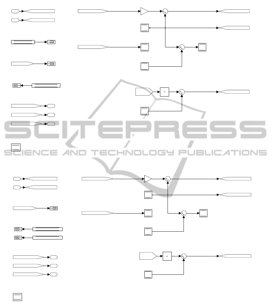
Inputs
Data Store Reads
Scoped Froms
Updates
Outputs
Declarations
3
2
1
z
1
[GotoOut13]
[GotoOut12]
[GotoOut10][GotoIn9]
[GotoIn15]
2
{Scoped1}
[GotoOut13]
[GotoOut12]
[GotoOut10]
[GotoIn9]
[GotoIn15]
{Scoped1}
A
B
C A
C
B
A
C
2
1
Figure 3: Subsystem Sub1 with included strong signature as generated by the Signature Tool.
Inputs
Scoped Froms
Updates
Outputs
Declarations
3
2
1
z
1
[GotoOut13]
[GotoOut12]
[GotoOut10][GotoIn9]
[GotoIn15]
2
{Scoped1}
[GotoOut13]
[GotoOut12]
[GotoOut10]
[GotoIn9]
[GotoIn15]
{Scoped1}
B
A
C A
C
B
A
C
2
1
Figure 4: Subsystem Sub1 with included weak signature as generated by the Signature Tool.
discipline of e.g., using scoped Goto/Froms for
static inputs and using inports for dynamic inputs,
would significantly declutter the explicit interface
of the subsystem.
• When the subsystem signatures are included in the
model, they can be used to incorporate strong typ-
ing into subsystems’ interfaces. For more details,
an interested reader is referred to (Bender et al.,
2014a).
3 THE REACH/COREACH TOOL
In this section, we present the Reach/Coreach Tool.
First, basic capabilities of the tool are introduced.
Then, its implementation and applications are ex-
AToolsetforSimulink-ImprovingSoftwareEngineeringPracticesinDevelopmentwithSimulink
55

plained.
3.1 Tool’s Capabilities
The Reach/Coreach Tool identifies dependencies in a
Simulink model in two different ways:
• Reach: For a specified set of blocks (e.g., a set
of inports), the tool identifies parts of the model
that depend on the specified blocks. The reach-
able model (the submodel of the original model
that consists of the identified blocks, and signals
that connect them) is then highlighted.
• Coreach: For a specified set of blocks (e.g., a set
of outports), the tool identifies parts of the model
that the specified blocks depend on. The coreach-
able model (the submodel of the original model
that consists of the identified blocks, and signals
that connect them) is then highlighted.
Once the Reach/Coreach submodel is identified and
marked in the Simulink model, the unmarked parts of
the model can be trimmed away: the remaining sub-
model represents a model slice.
The application of the tool on a simple example
is illustrated in Figures 5, 6, and 7. The coreachabil-
ity analysis for outport Out1 results in the submodel
marked in blue/yellow colours as shown in Figure 5
(with subsystem WhileSub from Figure 5 shown in
Figure 6). The reachability analysis done on inports
In1, In2, and In3 would result in the same submodel
being highlighted. The reachability analysis for Data
Store Write A in Figure 5 is highlighted in red/black,
with the subsystem Sub1 shown in Figure 7. Both
reachability and coreachability analysis preserve the
hierarchical structure of the model.
The Reach/Coreach Tool tracks and highlights
both data flow (data dependencies) and control flow
(control dependencies) in the model:
Data Flow. Data flow in Simulink is explained in
more detail in Section 2. The Reach/Coreach Tool
tracks the explicit data dependencies — the data flow
through signal lines. Assuming that changes to an in-
put propagate to changes in any output for any block
(except a subsystem), that is, any input can influence
any output of a block that is not a subsystem, and by
deducing the input-output influence relation of a sub-
system from the structure of its components, it is pos-
sible to construct the signal line dependency of the
model. However, as elaborated in Section 2, there are
hidden data dependencies in Simulink: the implicit
data flow through data stores and Goto/From blocks.
The Reach/Coreach tool tracks these data dependen-
cies as well. For example, in Figure 5, the flow from
the Data Store Write A block is tracked to Out2: this
comes from the fact that the data store is being read
in Sub1. Therefore, the Reach/Coreach Tool accounts
for implicit data flow in a model: the tool tracks not
only the data flow through inports/outports, but also
the data flow via data stores, and Goto/From blocks.
This is a major difference between our tool and that
of (Reicherdt and Glesner, 2012): their definition of
data dependency in Simulink does not account for the
implicit data flow. Also, it should be noted that the
Reach/Coreach Tool provides for fine-grained track-
ing of the data flow through Simulink buses.
Control Flow. Control flow logic in Simulink can be
implemented using If block and If Action subsystems
(for if-else logic), Switch Case block and Switch Ac-
tion subsystems (for switch logic), and While Iterator
and For Iterator subsystems (for loops). For example,
the outputs of If block are used to trigger If Action sub-
systems, depending on the evaluation of a specified
condition on inputs of the If block. Action subsystems
have an Action Port block: when the input at the port
evaluates to true, the subsystem executes. Inputs of If
block (Switch Case block) are reached to all the out-
puts of the block, all the Action subsystems and their
outputs. If coreachability analysis is performed from
the block whose input is the output of an Action sub-
system, it will trace back to Action Port, as well as
the data input(s) of the Action subsystem determined
by coreachability analysis inside the subsystem; Ac-
tion Port will be further traced back to all the inputs
of the If (Switch Case) block. Note that this is, in gen-
eral, an overapproximation of actual dependency: an
output of If (Switch Case) block can depend only on
one of the block’s inputs. When it comes to an Iter-
ator subsystem, each block in the subsystem is (con-
trol) dependent on the Iterator block in the subsystem,
and, therefore, on its inputs. For example, in Figure 5,
Out1 is dependent on all the inputs of WhileSub sub-
system, since the While Iterator (Figure 6) executes
contents of the subsystem based on IC (initial condi-
tion) and cond inputs.
4
Conditional subsystems Enabled Subsystem, Trig-
gered Subsystem, Enabled and Triggered Subsystem,
and Function-Call subsystems have a control input in
addition to data inputs: when this input satisfies a con-
dition, the corresponding subsystem is executed. For
each of those subsystems, outputs are dependent on
control inputs: when coreachability analysis is done
for one of these subsystems, it traverses through its
4
At the beginning of a time step, if the IC input does not
hold, the subsystem is not executed in that time step. If the
IC input does hold, the subsystem gets executed, and then,
if the cond input is true, the iterator executes the subsystem
again. The iterations continues while cond input is true and
the number of iterations is less than or equal to the Maxi-
mum number of iterations.
MODELSWARD2015-3rdInternationalConferenceonModel-DrivenEngineeringandSoftwareDevelopment
56
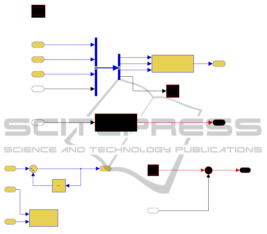
Out2
2
Out1
1
WhileSub
In1
In2
IC
Out1while { ... }
Sub1
In1
Out1
Data Store
Write A
A
Data Store
Memory A
A
In5
5
In4
4
In3
3
In2
2
In1
1
<signal1>
<signal2>
<signal3>
<signal4>
Figure 5: Illustration of Analysis with the Reach/Coreach Tool: Reach for Data Store Write A (red/black), Coreach for Out1
(blue/yellow); Subsystems WhileSub and Sub1 are shown in Figures 6 and 7, respectively.
Out1
1
While Iterator
while {
...
}
cond
IC
Unit Delay
z
1
IC
3
In2
2
In1
1
Figure 6: Subsystem WhileSub from Figure 5.
control input. Similarly, if reachability analysis tra-
verses to the control input of a conditional subsystem,
it is further propagated to all of the subsystem’s out-
puts. Of course, the dependency of outputs on data
inputs is determined by the Reach/Coreach analysis
inside the subsystem.
3.2 Implementation and Applications
The Reach/Coreach Tool is implemented using MAT-
LAB’s object-oriented programming facilities. The
Reach and Coreach algorithms are fixed-point algo-
rithms, that identify the immediate reached/coreached
blocks of a current set of blocks, starting from the ini-
tial specified set of block on which the Reach/Coreach
analysis is to be performed. The analyses times do not
exceed two seconds for any of the industrial models
that were used.
Out1
1
Data Store
Read
A
In1
1
Figure 7: Subsystem Sub1 from Figure 5.
Next, we elaborate on how the tool can be used in
a model-based development process.
Refactoring. The tool can be used to find in-
dependent/weakly dependent data flows — these
might be candidates to be separated into different
subsystems.
Comprehension. The Reach/Coreach Tool depicts
the dependencies in a Simulink model, effectively
representing its dependency diagram. While the sig-
natures address the comprehension issue at the level
of a subsystem, the Reach/Coreach Tool offers an
abstracted view of data and control flow from given
blocks backwards to inputs, or forwards to outputs.
Both the views generated by the Signature Tool, and
the views generated by Reach/Coreach Tool, are data
flow views — and, as claimed in (Quante, 2013):
“such views can be very helpful for tracking data
flows through a system — especially when there
AToolsetforSimulink-ImprovingSoftwareEngineeringPracticesinDevelopmentwithSimulink
57
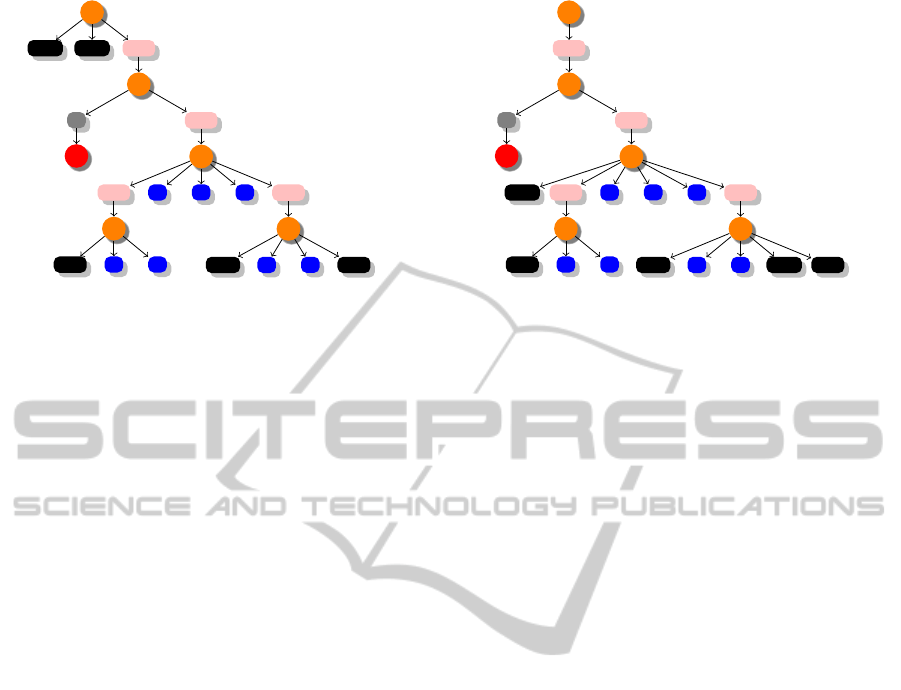
S
1
DS
M
A
DS
M
B
S
UB
2
S
2
R
1
F
1
SUB
3
S
3
S
UB
4
S
4
DSR
A
B
1
B
2
B
3
B
4
B
5
S
UB
5
S
5
DSW
A
B
6
B
7
DSR
B
Figure 8: Data store push-down: before.
are additional hidden dependencies.” Further, by
trimming the extraneous blocks from a model, it is
possible for a user to gain a greater understanding
of the structure of the model. For review purposes,
the Reach/Coreach analyses can assist reviewers in
fully grasping data and control dependencies in a
model: understanding the flow in complex models is
very hard without proper abstractions even when the
models are well-documented.
Dead Code. The tool can be used to find unreach-
able parts of a model: once the reachability analysis
is performed on all of model’s inputs (inports),
non-marked blocks/signals represent unreachable
parts of the model. When the coreachability analysis
is performed on all of model’s outputs (outports), the
extraneous blocks are unnecessary in the sense that
they have no (data or control) effect on the outputs of
the model.
Impact Analysis. Since the tool identifies the
parts of a model affected by a change of a given
block, it provides for impact analysis. The impact
analysis can be of great value in indicating what
effect a change in requirements can have on system’s
design. During both initial design and refactoring, the
tool can be used for preliminary evaluation of differ-
ent designs with respect to the extent that the future
anticipated requirements changes will have on the
system’s design. Therefore, the tool would help the
developer design for change. Further, impact analysis
can be extremely beneficial in alleviating verification
efforts, which are typically very large, especially
in the case of safety-critical systems. Verification
efforts can be decreased by focusing on the parts
of the system that the outputs (or, more generally,
the data items) of interest depend on: we view the
Reach/Coreach Tool as a useful means of providing
impact analysis that avoids the costly analysis of the
parts of the system that are not affected by a change.
S
1
S
UB
2
S
2
R
1
F
1
SUB
3
S
3
DS
M
A
S
UB
4
S
4
DSR
A
B
1
B
2
B
3
B
4
B
5
S
UB
5
S
5
DSW
A
B
6
B
7
DSM
B
DSR
B
Figure 9: Data store push-down: after.
4 THE DATA STORE
PUSH-DOWN TOOL
We have noticed that some of the industrial models
we have been working with define most of their data
stores at the top level of a model’s hierarchy. This
practice is analogous to programming using a large
number of global variables, and it is considered a bad
software engineering practice.
Data stores, like variables in traditional program-
ming languages, should be properly scoped in order
to disable inadvertent/unwanted access to the data
stores. Also, the proper scoping declutters the in-
terface of a subsystem by hiding low-level details of
the subsystem, therefore providing proper encapsula-
tion. Proper data store scoping also reduces the num-
ber of (implicit) inputs for testing, resulting in pos-
sibly fewer generated tests (test steps). Therefore,
proper scoping of data stores enhances comprehen-
sibility, maintainability, testability, and reusability of
Simulink subsystems.
In this section, the concept of the data store push-
down operation is discussed first. Then, tool’s imple-
mentation and applications are detailed.
4.1 Illustration of Data Store
Push-down Operation
We have already discussed scope associated with data
stores and Goto/From blocks. A block falls within the
scope of another block b if it is contained in a system
that belongs to the scope of the block b. Our goal is
to limit the scope of data stores as much as possible.
For example, if a Data Store Memory occurs high in
the model hierarchy, and there are two data store ref-
erences (Data Store Read or Data Store Write blocks)
lower in the hierarchy, the goal is to push-down the
data store (Data Store Memory block) to the smallest
MODELSWARD2015-3rdInternationalConferenceonModel-DrivenEngineeringandSoftwareDevelopment
58
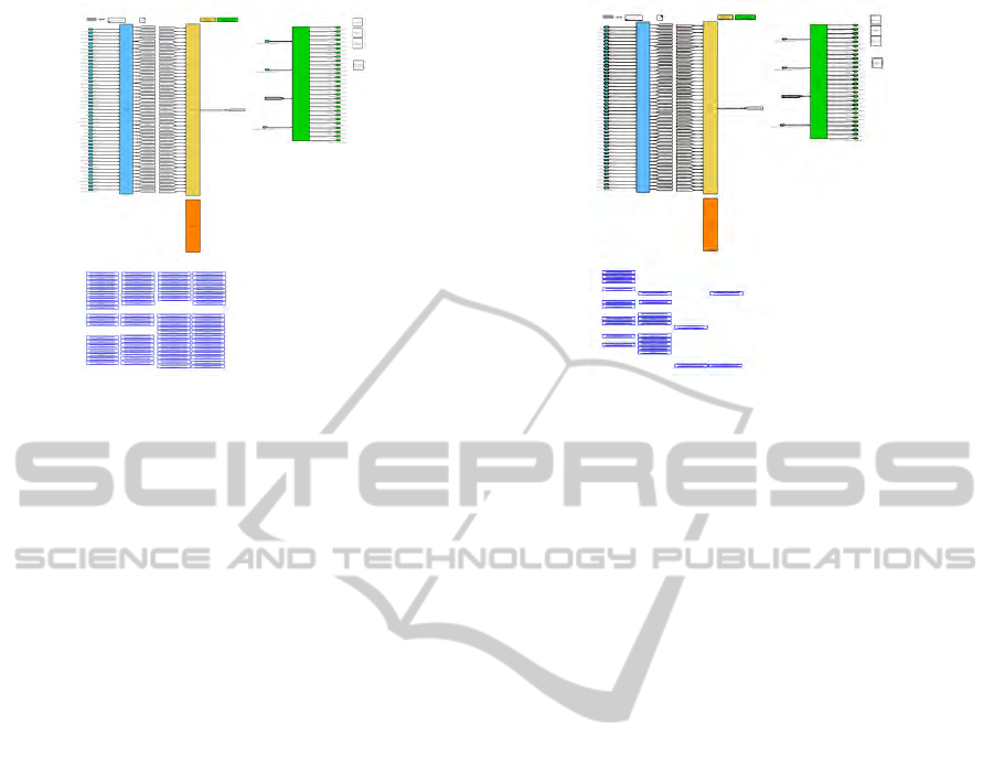
Figure 10: The top level of the industrial model before the
push-down operation.
subsystem such that both references are still within
the scope of the data store.
In Figure 8, a system is represented before the
data store push-down operation has been applied to
it. The orange nodes represent systems, the rectangu-
lar elements are blocks, the pink blocks are subsystem
blocks. Grey blocks are reference blocks (blocks that
refer to a block in another file, here denoted by a red
node). Arrows emanating from systems to blocks de-
note membership of the block in the system. An arrow
emanating from a subsystem block to system denotes
that the system is associated with the subsystem; sim-
ilar relationship exists for references and files. Fig-
ure 9 shows the system after the data store push-down
operation has been applied to it.
4.2 Implementation and Application
The push-down algorithm is implemented as a single
iterative MATLAB function. Firstly, the push-down
algorithm searches the model for all Data Store Mem-
ory blocks. Then, it searches for all the corresponding
Data Store Read and Data Store Write blocks. The ad-
dresses of these corresponding Data Store Read and
Data Store Write blocks are then parsed to find their
lowest common ancestor. Lastly, unless the lowest
common ancestors reside in a library linked subsys-
tem, the Data Store Memory blocks are then pushed
to their respective lowest common ancestors. Exe-
cution times of the algorithm on the large industrial
models (containing many Data Store Memory blocks
at the top level (around 50) and deep model hierarchy
(of depth 6)) do not exceed one second.
Given its importance, we propose proper scop-
ing of variables to be included in the modeling style
guidelines for Simulink. With Simulink/Stateflow
Figure 11: The top level of the industrial model after the
push-down operation.
emerging as a leading environment for model-based
design of embedded systems, a number of guide-
lines have been created to assist designers in mod-
eling. Guidelines typically provide a wide range
of rules/recommendations (e.g., naming conventions,
usage of Simulink patterns for different constructs
(e.g., case constructs), grouping of blocks into sub-
systems, etc.). In the automotive industry, the most
notable modeling standard is published by The Math-
Works Automotive Advisory Board (MAAB) (Math-
Works, 2014b). In addition, companies use in-house
guidelines to improve the quality of their software. In-
house guidelines typically contain a number of checks
from standard guidelines. Adherence to the rules
improves software testability, understandability, and
maintainability. Also, the compliance enhances sim-
ulation and code generation capabilities. For exam-
ple, each of the MAAB rules/recommendations for
Simulink/Stateflow is justified by one or more of the
following:
• Easily understood algorithms (readable models,
uniform appearance of models, code, and doc-
umentation, clean interfaces, professional docu-
mentation),
• Effective development process and workflow
(ease of maintenance, rapid model changes,
reusable components, etc.),
• Efficient simulation and analysis,
• Generation of code that is efficient and effective
for embedded systems,
• Ability to verify and validate a model and
generated code (requirements traceability, test-
ing, problem-free system integration, clean inter-
faces).
In order to include proper scoping of data stores in
modeling guidelines, a rule can be formulated to re-
AToolsetforSimulink-ImprovingSoftwareEngineeringPracticesinDevelopmentwithSimulink
59
4
3
2
1
In1
In2
Out1
Out2
1/s
1/s
1/s
1/s
1/s
1/s
1/s
1/s
[B]
[A]
0.5
0.5
[B]
[A]
3
2
1
green
Figure 12: Simulink Model: Before Layout.
quire that each data store (with certain exceptions) be
defined at the lowest hierarchy level such that all the
references to the data store are still within its scope.
The exceptions account for situations where a de-
veloper might desire to leave a data store defined at
a higher hierarchy level than currently needed fore-
seeing that the data store will be used in future by
other subsystem(s) at the same or higher hierarchy
levels. Therefore, the user of the tool should be able
to choose the data stores that should not be pushed
down the hierarchy. Our tool supports this feature. A
straightforward modification of our tool can then be
used to check for the compliance of a Simulink model
with the rule, and then repair the model (perform the
push-down operation) if needed so that the model ad-
heres to the rule.
An interesting synergy between signatures and the
push-down operation was demonstrated in (Bender
et al., 2014b). The push-down operation was ap-
plied on an industrial automotive model shown in
Figure 10. The number of data stores at the root
level (data stores are represented by blue rectangles
at the bottom of the figure) has been significantly de-
creased by the push-down operation as illustrated by
Figure 11 (not all the details in models in both fig-
ures are legible for confidentiality purposes). From a
software engineering perspective, the push-down op-
eration clears the interfaces of model’s subsystems
at different hierarchy levels: the impact of the push-
down operation is the largest for the subsystems at
the model’s root level. This change in subsystems’
interfaces is obvious with simple visual inspection of
their signatures as generated by the Signature Tool.
Further, the Signature Tool was used on the model’s
subsystems to calculate the difference in the number
of data items in a subsystem’s weak and strong sig-
nature: this metric as formalized in (Bender et al.,
2014b) and, as explained in Section 2, indicates the
quality of modularization of designs in Simulink. The
values of the metric for model’s subsystems, before
and after the push-down operation, indicate the sig-
nificant improvement in modularity realized by the
push-down operation.
4
3
2
1
In1
In2
Out1
Out2
1
s
1
s
1
s
1
s
1
s
1
s
1
s
1
s
[B]
[A]
0.5
0.5
[B]
[A]
3
2
1
green
Figure 13: Simulink Model: After Layout.
5 THE AUTO LAYOUT TOOL
In a modeling environment such as Simulink, the
readability of models is largely determined by graph-
ical layout of blocks and lines in the model. Since
most refactoring operations perturb model layout and
manual readjustment of model layout is a tedious and
error-prone process if performed manually, automatic
layout is viewed as an essential component of model
refactoring. However, there does not exist a com-
mercial tool that comprehensively tackles the auto-
matic layout of Simulink models. There are a number
of commercial tools that check Simulink models for
compliance with modeling style guidelines (MXAM
by Model Engineering Solutions (Model Engineer-
ing Solutions, 2014), Simulink Model Advisor by the
MathWorks (MathWorks, 2014a) with the Verification
and Validation Toolbox (MathWorks, 2014c), etc.).
These tools also offer automatic repair for some of the
rules once a model fails a rule; however, the repair
capabilities of these tools are modest at best. While
a number of layout algorithms have been proposed
(e.g., (Klauske and Dziobek, 2010; Klauske et al.,
2012)), to the best of our knowledge, no tools based
on these papers are available for download.
Our layout tool uses an already existing graph
drawing algorithm (Gansner et al., 1993) imple-
mented in Graphviz. Graphviz is a set of open-source
tools for drawing graphs represented by the DOT
graph description language. More precisely, our tool
harnesses the Graphviz’s layout engine dot for the au-
topositioning of model blocks; lines are then autogen-
erated using Simulink’s built-in automatic line posi-
tioning support. Graphviz’s tool dot uses the algo-
rithm of (Gansner et al., 1993) to rearrange blocks and
lines in a consistent, organized manner to maximize
readability (the same algorithm is also partially used
by (Klauske and Dziobek, 2010)). The tool resizes
blocks based on number of inputs and outputs, and
organizes the lines such that the number of crossings
is minimized. See Figure 12 for a model before au-
MODELSWARD2015-3rdInternationalConferenceonModel-DrivenEngineeringandSoftwareDevelopment
60

tomatic layout, and Figure 13 for the model after au-
tomatic layout. Note that model comprehension and
readability have markedly improved.
As opposed to the tools described in the previous
sections, this tool is at the proof-of-concept stage. We
are currently refining the layout engine to accommo-
date Simulink-specific layout requirements (for ex-
ample, outports should be placed on the right side,
unless they are moved to prevent crossings). Fur-
ther, we are also implementing a number of refactor-
ing transformations that are not natively automatically
supported by Simulink: e.g., splitting/merging sub-
systems.
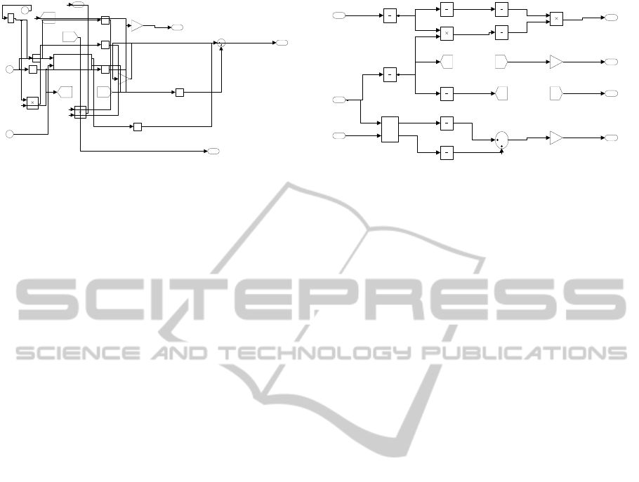
6 CONCLUSIONS
Automated support is an essential part of any soft-
ware development process. This paper presents a set
of tools that help automate the application of some
traditional software engineering practices when de-
signing with Simulink. While the paper illustrates the
use of the tools on simple toy examples, the tools have
been proven on large, industrial models from the au-
tomotive industry, that could not be presented in the
paper due to their proprietary nature. The concepts
presented in this paper, and tools based on the con-
cepts, represent the beginning of our investigation of
the issues of integrating some traditional software en-
gineering practices in design with Simulink.
REFERENCES
Bender, M., Laurin, K., Lawford, M., Ong, J., Postma,
S., and Pantelic, V. (2014a). Signature required:
Making Simulink data flow and interfaces explicit.
In Proceedings of 2nd International Conference
on Model-Driven Engineering and Software De-
velopment (MODELSWARD 2014), pages 119–131.
SCITEPRESS.
Bender, M., Laurin, K., Lawford, M., Pantelic, V., Ko-
robkine, A., Ong, J., Mackenzie, B., Bialy, M., and
Postma, S. (2014b). Signature required: Making
Simulink data flow and interfaces explicit. In Science
of Computer Programming, Special issue on Model-
Driven Development. Submitted in June.
Gansner, E. R., Koutsofios, E., North, S. C., and Vo, K.-P.
(1993). A technique for drawing directed graphs. Soft-
ware Engineering, IEEE Transactions on, 19(3):214–
230.
Klauske, L., Schulze, C., Spnemann, M., and von Hanxle-
den, R. (2012). Improved layout for data flow dia-
grams with port constraints. In Cox, P., Plimmer, B.,
and Rodgers, P., editors, Diagrammatic Representa-
tion and Inference, volume 7352 of Lecture Notes in
Computer Science, pages 65–79. Springer Berlin Hei-
delberg.
Klauske, L. K. and Dziobek, C. (2010). Improving
modeling usability: Automated layout generation for
simulink. In Proceedings of the MathWorks Automo-
tive Conference, MAC.
MathWorks, T. (2014a). Model Advisor. http://www.
mathworks.com/help/simulink/ug/consulting-the-
model-advisor.html. [Online; accessed September
2014].
MathWorks, T. (2014b). The MathWorks Auto-
motive Advisory Board. http://www. math-
works.com/automotive/standards/maab.html. [On-
line; accessed September 2014].
MathWorks, T. (2014c). Verification and
Validation Toolbox. http://www. math-
works.com/products/simverification/. [Online;
accessed September 2014].
Model Engineering Solutions (2014). MES Model
Examiner (MXAM DRIVE). http://www. model-
engineers.com/en/model-examiner.html. [Online; ac-
cessed September 2014].
Quante, J. (2013). Views for efficient program understand-
ing of automotive software. Softwaretechnik-Trends,
33(2).
Reicherdt, R. and Glesner, S. (2012). Slicing MATLAB
Simulink models. In Software Engineering (ICSE),
2012 34th International Conference on, pages 551–
561. IEEE.
AToolsetforSimulink-ImprovingSoftwareEngineeringPracticesinDevelopmentwithSimulink
61
