
Tool Integration by Models, Not Only by Metamodels
Applying Modeling to Tool Integration
Weiqing Zhang
Department of Informatics, University of Oslo, Oslo, Norway
Keywords:
Tool Integration, Models, Metamodels.
Abstract:
Integration of tools that support different models defined by different metamodels cannot be achieved by
integrating or merging the metamodels of the different models, or by making a minimum, common metamodel
for these models. However, it can be achieved by making common representatives of the various models
and model elements maintained by the tools. This paper has investigated several existing model/metamodel
integration approaches, and described an approach where tool integration works by models, not only by
metamodels.
1 INTRODUCTION
Tool integration in case of a number of tools working
on a common model in one language is simple, and
mechanisms for this are well known and established.
The various tools work on a well-defined API
towards one model repository. The case for most
real development projects is, however, rather that
various tools are involved, each supporting a separate
language, not working on a common model, and not
made with integration in mind.
For the purpose of the arguments in this paper, it
is assumed that a tool supports a language defined
by a metamodel. However, the arguments apply
just as well to tool supporting languages defined
by grammars and to tools that really just support
structured data without there being a real language
with syntax and semantics behind, and where the
metamodel defines the structure of data.
In order to come up with a solution to
tool integration, the following argument seems
straightforward:
(tools support languages) + (languages are defined
by metamodels) = (tool integration is solved by
metamodel integration)
It therefore seems tempting to solve real tool
integration by defining a common, integrated
metamodel based upon the metamodels of the various
languages supported by the tools. Tool integration
could be based upon a metamodel that is the union
of all involved metamodels. However, tools may be
added (and removed) dynamically, thereby changing
the union, and a metamodel union would just be a set
of unrelated metamodel fragments. In addition, tool
vendors would have to adhere to this metamodel.
Defining a brand newmetamodel that can cover all
of the involved metamodels will either be very large
(covering what a union of metamodels would do), or
it will just cover subsets of the involved metamodels.
These subsets may have overlapping concepts, so
a common metamodel would either have to merge
concepts or define mappings between the overlapping
concepts.
This paper will report on the findings from a
quite different approach of applying modeling to tool
integration. This modeling is based upon an industrial
case and on requirements from this.
The industrial case is a wind turbine project
(from ABB Norway). This project is to develop an
embedded system to control wind turbines. Sensors
are deployed around the wind turbines to collect the
environmental data. The control system contains two
modules executed on the same microprocessor: a
C code module generated from a Simulink model
for high speed performance, and a C code module
generated from an IEC 61131 (Rzonca et al., 2007)
model for low speed performance. The control
system performs calculations according to the sensor
data and sends commands to control the wind
turbine. A number of development tools from
different engineering domains are involved: A tool for
making requirements (IRQA), tools for designing the
IEC 61131 and Simulink models, and a traceability
tool for creating traces between these tool elements.
461
Zhang W..
Tool Integration by Models, Not Only by Metamodels - Applying Modeling to Tool Integration.
DOI: 10.5220/0005236604610469
In Proceedings of the 3rd International Conference on Model-Driven Engineering and Software Development (MODELSWARD-2015), pages 461-469
ISBN: 978-989-758-083-3
Copyright
c
2015 SCITEPRESS (Science and Technology Publications, Lda.)

A UML tool is used to specify class models that
are common to Simulink and IEC 61131 designs,
and then transform these class models into Simulink
and IEC 61131 tools through MOFScript (Object
Management Group, 2010).
For tool integration in real industrial cases, there
are a number of requirements to and constraints on
a tool integration approach:
• Tools. The approach shall be able to cope with a
changing set of tools and thereby a changing set
of metamodels for the languages supported by the
tools; tools may be updated due to enhancements
and new versions, and tools may be replaced by
similar tools.
• Metamodels. The approach shall support tools
for languages with different metamodels without
requiring privileges to change metamodels; and
it cannot be required that the metamodels of
the different tool are made with the same meta-
metamodel.
• Implementation. The approach shall be
independent of underlying realization platforms,
as these may change.
• Behavior. The approach shall support the
specification of tool integration activities as part
of integration processes for a changing set of
integration scenarios.
The most important finding from applying
modeling to tool integration is that a tool integration
approach that fulfills all these requirements is not
based upon a common integrated metamodel that
involves different tool metamodels, but rather on a
common model that defines representatives of the real
models/model elements.
The paper is organized as follows. Chapter 1 gives
the background and main issues in tool integration,
together with requirements. Chapter 2 describes a
number of approaches to tool integration and evaluate
them according to the requirements. Chapter 3 and
Chapter 4 describe the application of modeling to tool
integration. Chapter 5 describes an implementation
of the integration approach for a specific platform.
Finally, chapter 6 summarizes the paper.
2 APPROACHES TO TOOL
INTEGRATION
This section provides a description of various
approaches to tool integration. It also tells why we
have tried an alternative approach, by showing that
these approaches do not meet all the requirements
above, and it provides an account of related work,
although existing approaches will first be related to
the proposed approach as part of the presentation of
modeling approach in Chapter 4.
The Ipsen approach (Nagl, 1996) is a framework
for integrating tools through a common meta-model.
It supports integration of different tools with models
in different languages, but it requires that all of these
be represented in a uniform way. The Ipsen approach
has all models represented by graphs according to a
common metamodel for graphs. This approach is not
easily applicable to the integration of existing tools
with different languages defined in different ways.
EAST-ADL (Cuenot et al., 2007) illustrates that
a common metamodel approach may work for a
certain domain. EAST-ADL is an Architecture
Description Language (ADL) initially defined in the
ITEA project EAST-EEA. It is aligned with the
more recent AUTOSAR automotive standard. EAST-
ADL provides the means to capture the functional
decomposition and behavior of the embedded system
and the environment. Aspects covered include vehicle
features, requirements, analysis functions, software
and hardware components and communication. It
even supports for variability modeling.
However, in industrial projects tools may come
and go, and some tools do not even have standard
metamodels (e.g. the modelling tool Simulink), so
it is not feasible to have a common metamodel that
forms the base of different tools to be integrated.
(Diskin et al., 2010) presents heterogeneous
multimodels that capture specific system views, with
a framework to specify overlaps between partial
models and define their global consistency. The
approach is based on finding common views between
metamodels of the models involved, projecting all
models to these views, merging projections and
checking the result against the constraints specified
in these views.
The Fujaba (Burmester et al., 2005) is an open
source CASE tool providing developers with support
for model-based software engineering and reverse
engineering. It offers an extensible integration
platform with object-oriented software system
specification language (UML class diagrams and
specialized activity diagrams). Fujaba supports Java
code generation based on the formal specification
of a systems’ structure and behavior that results
in an executable system prototype. It allows
developers develop their own Fujaba plug-ins. It
focuses on modeling, validation and verification
of embedded real-time systems. Fujaba provides a
core metamodel to link to other tool metamodels
through integration patters like metamodel extension
MODELSWARD2015-3rdInternationalConferenceonModel-DrivenEngineeringandSoftwareDevelopment
462

pattern or integration pattern. Fujaba requires to
access to other tools metamodels and the ability
to change these. In Fujaba Tool Suites different
tools interoperate on a common meta-model with
a common consistency management system. The
metamodels of the different integrated tools are
required to be made with the same meta-metamodel
environment that provided by Fujaba itself.
Although SUM-based software engineering
(Atkinson et al., 2013) is not said to support tool
integration specifically, it is in fact a proposal to
go back to (or really to have the future become as)
the situation that different tools work on a single
underlying model, which is in fact the idea behind
the acronym SUM: Single Underlying Model. The
single underlying model is supposed to store all
known information about a system, except layout
information, which is the responsibility of the various
tools that provide different views onto the single
underlying model. This would correspond to an ideal
storage model for a metamodel-based model of a
system, e.g. a UML model according to the UML
metamodel, as the UML metamodel does not contain
any layout information either. In practice, however,
UML tools may store models in a mixture of pure
metamodel structures and layout information. In
order for all tools providing the different views to
access the information in the SUM they all have to be
made based upon the metamodel in which the SUM
is made. In that respect the SUM approach does not
fulfill the requirement that it should be possible to
integrate tools that support different languages with
different metamodels. It is also difficult to imagine
a common metamodel for e.g. UML and Simulink,
and even if it was defined, to have the tool vendors
(re)make their tool accordingly.
The Corum approach (Woods et al., 1998)
suggests the usage of a common information model
that is used by all tools. For the integration of tools
that are not based on the Corum approach and that
cannot use the Corum API, input can be generated by
means of transformation tools.
The OSLC (Open Services for Lifecycle
Collaboration, 2013) approach finds an agreement
among the stakeholders on specification for tool
integration. The key concepts are a uniform access
to shared resources, a common vocabulary/formats,
and a loose coupling approach between tools through
REST architectures (Fielding, 2000). OSLC is
dedicated to software lifecycle management, without
the ability to specify the behavior of integration.
The following two references point to the same
effort/project. While one of them (Kramler et al.,
2006) say that the topic is tool integration, the
other (Kappel et al., 2006) calls it model integration.
ModelCVS (Kramler et al., 2005) supports semantics-
based integration by lifting the various metamodels to
ontologies. From there elements of the ontologies are
mapped. This forms bridges between the metamodels
and these are in turn reflected in transformations
between models. The first approach of the CESAR
project was based upon a CESAR Common Meta-
Model (Baumgart, 2010). The CESAR Meta-
Model is a semantical conceptual meta-model and
is independent from a concrete implementation.
It defines a common terminology with conceptual
elements and relationships allowing a common
understanding of information that is exchanged
among system engineers of different domains. It
contains modeling concepts that are of common
interest for the different industrial domains aerospace,
automotive, automation and railway. The CESAR
Common Meta-Model is more like a terminology
model rather than a metamodel that defines abstract
syntax of a language.
MOFLON (Amelunxen et al., 2008) provides
transformation/mapping between elements of two
models for tool integration purpose. Using
MOFLON, developers can generate code for specific
tools needed to perform analysis and transformation
on one development tool or to incrementally integrate
data of different modeling tools.
3 MODELING OF THE TOOL
INTEGRATION DOMAIN
This approach has come about by applying
modeling to the domain of tool integration. The
requirement that the approach shall be independent of
underlyingrealization platforms (the Implementation-
requirement) is a good reason to apply modeling.
As for all kinds of modeling it has identified the
important concepts of the domain. However, in
contrast to existing approaches it has also applied
modeling to the activities that tool integration shall
support.
Distinction is clarified between domain models
and metamodels. A domain model is a model where
classes represent common concepts in the domain,
while a metamodel defines the abstract syntax of a
language. A domain model may be used to get to
an agreed understanding of a domain thus to analyse
this domain. It may form the basis for a collection
of classes that can be used in modeling of systems
within the domain (using general purpose modeling
languages), and it may form the basis for a metamodel
for a (domain specific) language.
ToolIntegrationbyModels,NotOnlybyMetamodels-ApplyingModelingtoToolIntegration
463
3.1 Concepts of Tool Integration
The basic concepts of the tool integration domain are
Tools, Models and Model Elements.
A tool is a software application that developers
use in various software development lifecycle phases
to create, analyze, design, debug, test, and maintain
programs, or otherwise support other applications.
Tools support the different development phases like
requirement analysis, design, implementation, testing
and maintenance.
Model elements are fully owned, managed, stored
and presented by the tools that create them. Model
elements are manipulated through tool APIs and
can be imported from other tools through standard
interchange format such as XMI. Elements may be
composed of other elements. For example, a model is
just a topmost artifact that consists of model elements,
and a model element can be composed of other model
elements which are also elements.
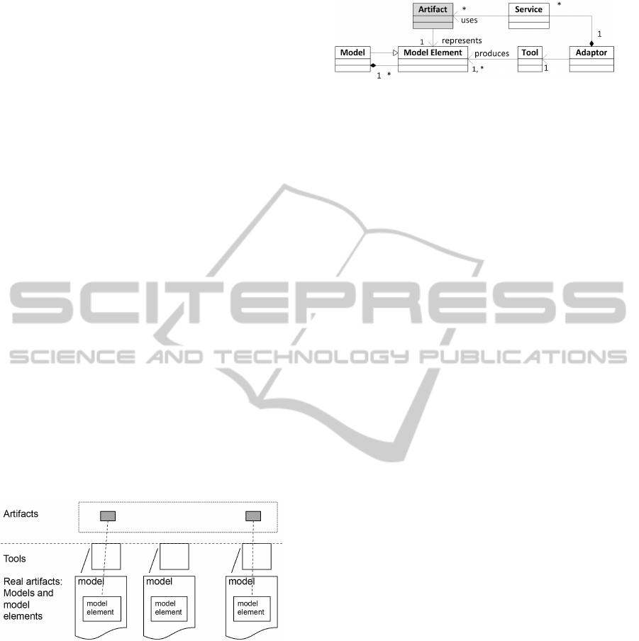
In figure 1 it is illustrated how to represent the real
model element artifacts by means of Artifact objects.
In modeling terms, the class Artifact are defined with
common integration properties so that Artifact objects
may represent real model elements in real models
maintained by real tools. Different models in different
languagesmay have differenthierarchyconcepts, thus
an Artifact may represent different levels of tool
elements, e.g. a whole model, or a whole data set,
or a part of a model/data set, or a single tool element.
Figure 1: Concepts of the Approach.
The implication of this modeling approach is
that while tools maintain individual models, tool
integration can be modeled based on this common
model of Artifacts. Only model elements that are
involved in tool integration will be represented by
Artifacts. The related conceptual model is given in
figure 2.
A tool adaptor exposes a set of integration
services, through which models and model elements
are integrated through Artifact representatives. For
example, a tool adaptor might provide services such
as creating a model element of a certain type. A
tool adaptor contains definitions of several kinds of
Figure 2: Conceptual Model.
Artifacts that it can handle, and it uses these as
parameters and results of its services.
3.2 Behavior in Tool Integration
In order to find out what is required in addition to
these basic concepts it is important to examine what
tool integration involves, i.e. what is done by means
of tool integration. For this it one may consider what
users of tools are doing when tools are not integrated.
Without support for tool integration, the users of the
tools perform the integration themselves.
This is the essence of the type of activity
being carried out by using (integrated) tools: The
making/updating of one or more model elements (by
using the appropriate tools) by involving one or more
other model elements (again by using the appropriate
tools). This may be further detailed by looking into
the two main things in this type of activity.
Making/updating can be reduced to a sequence
of making/updating one model element. The making
of the next model element in such a sequence
may still involve the model element that was just
made/updated.
Involving may mean the following:
1. A model element may be set to relate to model
elements in other tools:
(a) Without tool integration the relations between
model elements are maintained manually; if
only relations between few tools are required
then they may be kept in forms that are tool-
specific.
(b) With tool integration the involved model
elements still have to be selected by the user,
but the relations between model elements are
maintained as the related model elements are
independent of tool formats.
(c) Example: to trace model elements based upon
their representatives – Artifacts.
2. A model element is made from a transformation
of an involved model element:
(a) Without tool integration the user has to launch
a transformation, and either make or update
a model element from the outcome of the
transformation.
MODELSWARD2015-3rdInternationalConferenceonModel-DrivenEngineeringandSoftwareDevelopment
464
(b) With tool integration the user may specify that a
given condition should trigger the launching of
a transformation, and update a model element
from the outcome of the transformation.
(c) Example: A class that defines Temperature
in UML is transformed into Simulink block,
through Artifact properties like ”URL”,
”metamodel”, etc..
3. A model element is made/updated based upon
information extracted from a set of model
elements:
(a) Without tool integration, the extracted
information may be recorded in some arbitrary
tool (Word, Excel ) and then manually used
when updating the model element: either the
extracted information is directly used to update
the model element, or the user has to update
the model element based upon the extracted
information.
(b) With tool integration and with specification of
where extracted information should be used in
the model element, then modifying the involved
model elements may trigger the update; in
simple cases the update may be specified as
well, otherwise the user still has to make the
update based upon the extracted information.
item Example: Configuration data from one
model used in another model.
Updating also includes deleting, as this may have
implications for other (related) model elements.
Activities that simply use the available tool
services for maintaining models are not classified as
integration activities, as these activities do not involve
services of other tools, even though these may be far
more elaborate and advanced than the (integration)
activities listed above.
Note that in order to cover the above activities
it is not required to make one common model from
all the models of the tools to be integrated. The
focus of tool integration is still on the various models,
not on a combined model. Tool integration is
not model integration. Although data integration
is one important aspect of tool integration, model
integration may easily lead to the notion of integrated
metamodels in the hope that tool integration will
imply a grand model where each tool does part of
work.
From the above analysis, it appears that what is
required is the support for making integration models:
models that work on Artifact objects and specify the
activities that users of tools otherwise have to do
manually and repeatedly. From the definition of tool
integration above, the main thing is a sequence of
making/updating one model element, based upon the
involvement of other model elements. This sounds
like activity modeling or process modeling in general.
However, it should be possible to specify integration
models that are much simpler than these kinds of
models. Activity and process models are intended
for specification of processes that are independent of
using tools. The next chapter therefore investigates
what would be the tool integration answer to activity
and process models in general. With tool integration
as the domain, this would be a Domain Specific
Language for making tool integration models.
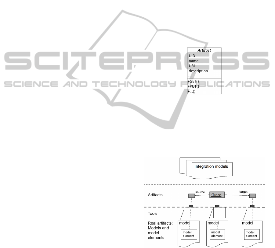
The basis for the behavior part of integration
models will be the operations that can be performed
on model elements through operations on Artifact
operations, see figure 3.
Figure 3: Artifact Class with operations.
In figure 4 it is indicated that if an integration
model specifies traces between model elements, and if
a trace tool does this, then a trace will be represented
by a Trace Artifact object with trace links to Artifact
objects. The real trace is a model element in a trace
model maintained by a trace tool.
Figure 4: Integration Models.
In order to complete the picture, the approach
requires that tools will have to implement Adaptors,
and based upon the definition of Artifacts implement
services that may manipulate the real model elements.
These Adaptors have been included in figure 4.
Developers will still use the tools as they are, and
the tools have their internal way of handling model
ToolIntegrationbyModels,NotOnlybyMetamodels-ApplyingModelingtoToolIntegration
465
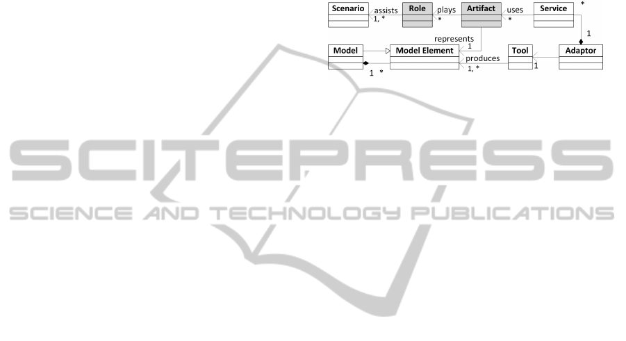
elements, but for the purpose of tool integration it is
possible to manipulate model elements by means of
Artifact objects via the Adaptors, and, as illustrated
in figure 4, make integration elements (here a trace)
based upon the Artifact objects instead of the real
model elements.
There is a general Artifact class with properties
that are common to model elements of all tools,
such as unique identifier (UID), name, URI of the
represented model elements, description, etc.
Tool-specific Artifacts are defined to specify tool
specific properties. The tool-specific Artifacts only
require properties that have to do with the represented
model elements. For instance, integrating a UML
model element requires the metamodel and metaclass
of the involved UML model element. Thus the
UML Artifact should contain a metamodel property
and metaclass property. Similarly, a Transformation
Artifact contains properties like source and target,
which point to the Artifact objects that represent the
source model and the target metamodel, respectively.
3.3 Changing Set of Integration
Scenarios
With respect to the Behavior-requirement, the
approach shall support the specification of a changing
set of integration scenarios.
Different scenario-specific information is required
when a model element (represented by an Artifact
object) is involved in different integration scenarios.
This information is unpredictable and cannot be
predefined. Thus Roles are designed to have scenario-
specific information that is required for integration,
but cannot be obtained through Artifact. E.g., a
UML class, represented by a UML Artifact, may be
transformed into different models when it applies to
different semantics. The semantics information is
captured through a Role.
A more completed conceptual model is illustrated
in figure 5. Role models are dynamically attached
to or removed from Artifact models. As presented
in (Steimann, 2000), the Role concept is associated
to an object of a native type and provides a flexible
way to grant semantic rigidity for this native type.
Objects of Role models are associated to other objects
that are indivisible for their semantics. In this
approach, the native type for other objects is the
Artifact models. As Artifact models are all predefined
classes without knowing the specific information
of integration scenarios, Role models remedy this
shortcoming and provide additional essential scenario
information.
One Artifact may be used differently in different
integration scenarios, i.e. it plays different Roles
in different scenarios. For instance, a UML Class
available in a modeler and used in the Design
and Implementation phase could be used differently
in the Requirement and Analysis phase. Without
capturing precise integration context through Roles,
the semantics can be misinterpreted and leads to tool
integration failure.
Figure 5: Complete Conceptual Model.
The integration engineers design Artifact models
before they make adaptors for integrated tools.
Attaching Roles to Artifacts resembles the use
of stereotypes on UML model elements and in
general annotations of model elements. However,
Roles attached to Artifacts have several advantages
compared to stereotyping/annotating the model
elements directly, such as:
• defining Roles attached to Artifacts make it
independent of how tools would represent
stereotypes/annotation, and in addition with
standardization across integrated tools;
• with Roles it is possible to include tools that
do not support stereotypes/annotations on their
model elements (e.g. Simulink);
• while stereotypes/annotations are fixed at the
time models are made, Roles can be dynamically
attached to Artifacts and thereby support
integration scenarios independently of when the
models are made.
4 ON INTEGRATION MODELS
This chapter describes an analysis of integration
models and how they would be specified. There are
very few existing approaches that have the notion of
integration model, and which is for future work.
These are the ingredients of integration models:
1. Predefined types and specifications
(a) Artifact and Role classes
(b) Adaptors and Tools
2. Integration Models with
(a) Specification of tools and their connections
(b) Integration Activities
MODELSWARD2015-3rdInternationalConferenceonModel-DrivenEngineeringandSoftwareDevelopment
466

1 are classes and specifications that are common
to a number of integration models. For a given
integration model it must be specified which tools are
involved and which integration activities to perform.
When activities perform they work on Artifact and
Role objects and they perform services provided by
specific Tools with specified Adaptors.
1 may be made by tool integrators, while 2 are
made by users of the tools. 1.(b) specify Adaptors
and constraints on connections of tools. 2.(a) may be
shared by a number of 2.(b), i.e. integration activities
that use the same set of tools.
If users are just interested in making applications
that perform integration, 1 may be used as the basis
for generation of APIs. However, these APIs have to
be made in a given implementation language.
In the same way as 1 is specified independently
of any implementation language, 2 may also
be specified by models and thereby independent
of implementation language. While integration
applications may be implemented in a general-
purpose programming language and thereby be
flexible wrt the kind of activities, an integration
model should be restricted to specify integration
activities that are within the constraints specified for
tool integration. This is similar to the rationale
for making a DSL: while making applications in a
general language is flexible (and thereby possibly
violating constraints of the domain), models in a DSL
ensure constraints of the domain.
By their very nature integration models are
general in that they act on Artifact objects of given
types. If distinguishing between integration models
and base models, where base models are the models
maintained by tools, while integration models specify
the integration, then an integration model can be
applied to multiple sets of base models that are
compliant to the involved types of Artifacts. Thus an
integration model that involves a set of Artifacts can
be applied to different compliant base models. For
example, a traceability integration model works on
both a tool chain that contains IRQA, Rhapsody, and
Simulink, and a tool chain that contains HP Quality
Center, Papyrus, and Simulink.
As integration information is independent of base
models (except for the links to the base model
elements represented by Artifact objects), updating
or adding integration information (as integration
scenarios are changed or added) will not have to
specify how to handle the involved base models.
Distinction of base models and integration models
brings several benefits. As integration information
is fully independent of base models, the updates or
changes of integration information will not affect
base models. This implies more flexibility and
convenience to adjust evolving integration models
and apply to base models as integration context
changes.
An integration model can be applied to multiple
base models that are compliant to the same tool
types. As the generic feature provided by tool
type concept, the tool-specific Artifacts represent
certain kinds of tool elements that are compliant
to the same tool metamodels. Thus an integration
model that consists of same group of Artifact models
can be applied to different compliant base models.
For example, a traceability integration model works
on both tool chain that contains IRQA, Rhapsody,
and Simulink, and tool chain that contains HP
Quality Center, Papyrus, and Simulink. It means
the same integration model works for tool data from
different tools but with the same tool types and same
integration process. Even if there are two different
tool chains, but the tools belongs to the same tool
types and used in the same integration scenario, the
same kind of integration code is generated from the
above traceability integration scenario to support the
integration.
Moreover, different integration models are also
possible to apply to the same base model, for
the purpose of generating different integration code
according to different integration scenarios for tools
of the same tool chains. This means tools of the
same tool chain are integrated based upon different
integration processes that are caused by different
integration scenarios. As Role models and process
models tightly adhere to integration scenarios, in
this case same Artifacts and different Roles are
choreographed through different process models.
Integration models are also convenient for tool
chain maintenance, as by code generation it is easy
to modify the integration models, and re-generate
the integration code. Once the integration model
is defined, it can be applied many times in later
implementation for different tool chains. More code
generation details are discussed in (Zhang et al.,
2012) (Zhang, 2013).
5 IMPLEMENTATION
This approach is independent of specific web
service implementation technologies. For illustration
purpose, OSLC has been adopted as a platform in
a tool integration project (iFEST Project, 2013). It
implies that adaptors work on representatives of the
real artifacts of tools in terms of resources, and that
these have to be specified in terms of OSLC-tables
ToolIntegrationbyModels,NotOnlybyMetamodels-ApplyingModelingtoToolIntegration
467
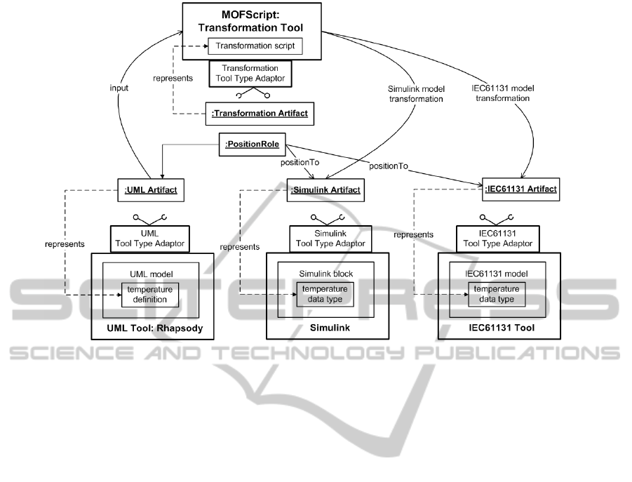
Figure 6: Apply Integration Models to Exchange Common Data Scenario.
of properties (OSLC specifications). The defined
integration model is mapped into OSLC concepts,
e.g. Artifact model maps to OSLC Resource Shape,
and Artifact object maps to OSLC Resource, etc.
OSLC is used to support lifecycle data sharing and
link lifecycle data (e.g. requirements, defects, test
cases, plans, or code) during the whole software
development process.
The integration models and tool metamodels are
used as inputs to generate OSLC web service as
integration base, mainly for integration adaptors. The
generation outputs are the multiple Resource Shapes
for query, update or creation usage that can be
used in the ServiceProvider resources. Additionally
the reference to the resourceShape included in the
common properties is generated containing the full set
of properties if the Typed resource.
In addition, through implementing such
specification, adaptors also specify services that
are dedicated on tool integration purpose. Model
transformation (Zhang, 2013) is used to generate part
of adaptor implementations (server and client code)
that adhere to the OSLC specification.
Figure 6 demonstrates the exchange common
data scenario from the ABB industrial case. Data
handled by applications made by different tools
are exchanged. In this case, a common data
type Temperature is defined and shall be available
in both Simulink and IEC61131, and at runtime
the applications made in these two languages/tools
should be able to exchange Temperature values.
Given (predefined) metamodels for Simulink and
IEC61131, the transformations produce two model
elements according to the two metamodels, and
the adaptors will then be able to produce the
corresponding real model elements.
The transformation tool retrieves the UML class
through a UML tool type Artifact, and transforms
the common data type definition to fragments of
models in both Simulink and IEC61131. The
generated Simulink and IEC61131 model fragments
are similarly represented by Model Element Artifacts.
A common data type Temperature, defined in UML,
is available in both Simulink and IEC61131, and the
parts of the system made by these two languages are
able to exchange Temperature values.
Below are the steps of using integration models:
1. analyze the integration scenarios and construct the
integration models, in particular identify services
that can be provided in a SaaS architecture;
2. with MDA transformation technology, transform
the integration models to target code like WSDL
or JEE Annotation;
3. Establish the Web Services based on the RESTful
(OSCL specific);
4. Complete the service-base server/client
implementation by invoking the identified
functions and service points from the integrated
tools, with desired data;
5. Identify a suitable cloud computing platform
MODELSWARD2015-3rdInternationalConferenceonModel-DrivenEngineeringandSoftwareDevelopment
468

to support the execution of the Web Services
according to the specific requirements of the
target system, and deploy the Web Service
providers to the selected platform;
6. End users consume the integrated tool chain
functionalities through the Web Services that run
on the cloud.
The result is a set of new Web Service applications
running in the service cloud, which looks, behaves
and maintains workflows just like a fully integrated
tool chain that is provided as a SaaS in the cloud.
6 CONCLUSION
This paper has presented a model-based approach to
tool integration that fulfills industrial requirements.
The approach copes with a changing set of tools and
thereby a changing set of metamodels without relying
on a common or an integrated metamodel, and it
copes with a changing set of integration scenarios.
The approach does not require privileges to change
metamodels: Artifacts representing model elements
simply have properties that provide the metamodel
and metaclass (and meta-metamodel if required) of
the model elements. By virtue of being based
upon a modeling of tool integration, the approach is
independent of underlying realization platforms.
REFERENCES
Amelunxen, C., Klar, F., K¨onigs, A., R¨otschke, T., and
Sch¨urr, A. (2008). Metamodel-based tool integration
with moflon. In Proceedings of the 30th international
conference on Software engineering, ICSE ’08, pages
807–810, New York, NY, USA. ACM.
Atkinson, C., Gerbig, R., and Tunjic, C. (2013). A multi-
level modeling environment for sum-based software
engineering. In Proceedings of the 1st Workshop
on View-Based, Aspect-Oriented and Orthographic
Software Modelling, VAO ’13, pages 2:1–2:9, New
York, NY, USA. ACM.
Baumgart, A., editor (01/2010). A common meta-model
for the interoperation of tools with heterogeneous data
models.
Burmester, S., Giese, H., Hirsch, M., Schilling, D., and
Tichy, M. (2005). The fujaba real-time tool suites:
model-driven development of safety-critical, real-time
systems. In Software Engineering, 2005. ICSE 2005.
Proceedings. 27th International Conference on, pages
670–671.
Cuenot, P., Frey, P., Johansson, R., Papadopoulos, Y.,
Reiser, M.-O., Sandberg, A., Servat, D., Kolagari,
R. T., Torngren, M., and et al. (2007). The east-
adl architecture description language for automotive
embedded software. In Giese, H., Karsai, G., Lee,
E., Rumpe, B., and Sch?tz, B., editors, Model-Based
Engineering of Embedded Real-Time Systems, volume
6100 of Lecture Notes in Computer Science, pages
297–307. Springer.
Diskin, Z., Xiong, Y., and Czarnecki, K. (2010).
Specifying overlaps of heterogeneous models for
global consistency checking. In Dingel, J. and
Solberg, A., editors, MoDELS Workshops, volume
6627 of Lecture Notes in Computer Science, pages
165–179. Springer.
Fielding, R. T. (2000). Architectural Styles and the Design
of Network-based Software Architectures. Phd thesis,
University of California.
iFEST Project (2010- 2013). ifest - industrial framework for
embedded systems tools. ARTEMIS-2009-1-100203.
Kappel, G., Kapsammer, E., Kargl, H., Kramler, G., Reiter,
T., Retschitzegger, W., Schwinger, W., and Wimmer,
M. (2006). On models and ontologies - a semantic
infrastructure supporting model integration. In Mayr,
H. C. and Breu, R., editors, Modellierung, volume 82
of LNI, pages 11–27. GI.
Kramler, G., Kappel, G., Reiter, T., Kapsammer, E.,
Retschitzegger, W., and Schwinger, W. (2006).
Towards a semantic infrastructure supporting model-
based tool integration. In Proceedings of the 2006
international workshop on Global integrated model
management, GaMMa ’06, pages 43–46, New York,
NY, USA. ACM.
Kramler, G., Retschitzegger, W., and Schwinger, W. (2005).
Schwinger: Modelcvs - a semantic infrastructure for
model-based tool integration. Technical report.
Nagl, M., editor (1996). Building Tightly Integrated
Software Development Environments: The IPSEN
Approach, volume 1170 of Lecture Notes in Computer
Science. Springer.
Object Management Group (2010). MOF Model to Text
Transformation. OMG Document ad/05-05-04.pdf .
Open Services for Lifecycle Collaboration (2013). OSLC
- Open Services for Lifecycle Collaboration Core
Specification Version 2.0 .
Rzonca, D., Sadolewski, J., and Trybus, B. (2007).
Prototype environment for controller programming in
the iec 61131-3 st language. Comput. Sci. Inf. Syst.,
4(2):133–148.
Steimann, F. (2000). On the representation of roles
in object-oriented and conceptual modelling. Data
Knowledge Engineering, 35(1):83–106.
Woods, S., O’Brien, L., Lin, T., Gallagher, K., and Quilici,
A. (1998). An architecture for interoperable program
understanding tools. In Proceedings of the 6th
International Workshop on Program Comprehension,
IWPC ’98, pages 54–, Washington, DC, USA. IEEE
Computer Society.
Zhang, W. (2013). Class modeling of oslc resources.
Technical Report, University of Oslo.
Zhang, W., Leilde, V., Moller-Pedersen, B., Champeau, J.,
and Guychard, C. (2012). Towards tool integration
through artifacts and roles. In The 19th Asia-Pacific
Software Engineering Conference.
ToolIntegrationbyModels,NotOnlybyMetamodels-ApplyingModelingtoToolIntegration
469
