
A Personalized Rehabilitation System based on Wireless Motion
Capture Sensors
Pedro Macedo
1,2
, José A. Afonso
1
and Ricardo Simoes
2,3,4
1
Department of Industrial Electronics, University of Minho, Guimarães, Portugal
2
Institute for Polymers and Composites IPC/I3N, University of Minho, Guimarães, Portugal
3
Life and Health Sciences Research Institute (ICVS/3Bs), University of Minho, Braga, Portugal
4
School of Technology, Polytechnic Institute of Cávado and Ave, Barcelos, Portugal
Keywords: Motion Capture, Physiotherapy, Wireless Sensor Networks, Wearable Sensors.
Abstract: We live in an aging society, an issue that will be exacerbated in the coming decades, due to low birth rates
and increasing life expectancy. With the decline in physical and cognitive functions with age, it is of the
utmost importance to maintain regular physical activity, in order to preserve an individual’s mobility, motor
capabilities and coordination. Within this context, this paper describes the development of a wireless sensor
network and its application in a human motion capture system based on wearable inertial and magnetic
sensors. The goal is to enable, through continuous real-time monitoring, the creation of a personalized
home-based rehabilitation system for the elderly population and/or injured people. Within this system, the
user can benefit from an assisted mode, in which their movements can be compared to a reference motion
model of the same movements, resulting in visual feedback alerts given by the application. This motion
model can be created previously, in a ‘learning phase’, under supervision of a caregiver.
1 INTRODUCTION
Physiotherapy is a therapy which aims to help
recover movement and restore normal body
function, when a person is affected by illness, injury
or disability. Musculoskeletal, neuromuscular,
cardiovascular and respiratory are some of the
physical problems physiotherapists can help treat.
Both physical and cognitive functions decline
with aging. Compensatory and preventive
management can control the effects of physiological
system decline. Generally people reach their peak of
performance abilities and health at ages between
adolescence and 30 years. After this period, it is
known that functional capacity declines throughout
the person’s lifespan, depending on genetics,
lifestyle and overall health (Nitz and Hourigan,
2004).
Physiotherapy plays an important role in this
aging society. Well trained health care professionals
in this area can assist the patient in the rehabilitation
process and improve his quality of life. It is
important to maintain constant physical activity, in
order to preserve movement ability, physical
adaptability, mobility and coordination of the
individual, by his own means or with assistance,
whether at home or in an assisted living facility.
Movements can be categorized within three levels:
active movement, which describes the movement
that a can be initiated and controlled independently;
assisted active, where in order to achieve a complete
movement some initial and control movement effort
has to be taken from the resident, with the caregiver
assistance; and passive movement, where all the
movement is performed by the caregiver. Among the
many benefits of doing exercise, we can cite the
improvement of strength, increased range of motion,
improved flexibility, improved functional mobility,
increased self-esteem, improved posture, improved
gait, improved efficiency of movement and
improved quality of life (Nitz and Hourigan, 2004).
Taking this into consideration, this project aims
to create a platform which enables and supports the
practice of physical activity; and/or serve as a
support platform for home-based physical
rehabilitation, providing feedbacks concerning the
correctness of the executed movement.
In the case of rehabilitation, the physiatrist
and/or the physiotherapist will assess the nature of
the patient’s problems, set goals based on the extent
220
Macedo P., Afonso J. and Simões R..
A Personalized Rehabilitation System based on Wireless Motion Capture Sensors.
DOI: 10.5220/0005238202200228
In Proceedings of the 4th International Conference on Sensor Networks (SENSORNETS-2015), pages 220-228
ISBN: 978-989-758-086-4
Copyright
c
2015 SCITEPRESS (Science and Technology Publications, Lda.)

of those problems, provide an adequate treatment
and continuously evaluate the patient’s progress.
Physiatry, or rehabilitation medicine, has as one of
its main aspects the recognition of functional deficits
caused by injury or illness. The identification of
these deficits is of utmost importance, in order to
best implement a proper treatment program to
restore the patient’s performance (Braddom, 2006).
A superior treatment can only be taken if the
physiatrist is fully aware of the patient’s history and
difficulties he may have conducting the prescribed
exercises. According to the author (Braddom, 2006),
there are seven levels of disabilities. The level 1 of
the scale is the most critical case, where total
assistance is needed and the patient expends less
than 25% of the effort. The scale from 1 to 5
encompasses a dependent disability, meaning that
the patient requires another person to either
supervise or assist in the performed activity; whereas
in scales 6 to 7 assistance in not necessary to
perform the activity.
Normal activities of daily living (ADL) like
bathing and showering, dressing, eating and
functional mobility, may suffer due to any existing
physical problem. The combination of these
problems, adding to the effort that some activities,
like standing up, sitting down or picking up things,
exert in our body joints, leads, in extreme cases, to
the use of a prosthetic device to preserve the
person’s quality of life. Total hip replacement and
rehabilitation is a perfect example of the interaction
that should exist between the patient and his
caregiver. After the surgery, in order to achieve a
satisfactory level of functionality and independence
in the patient’s daily life, it is important to continue
with the prescribed daily exercises. Patients with hip
replacement have limited motion amplitude, so
movements have to be restricted during the first
three months after the surgery. Flexion above 90º
and flexion combined with abduction movements
should be avoided, to prevent the prosthesis
displacement (Brander and Stulberg, 2006) (O’Leary
et al., 2011).
The continuous growth of the ratio of elderly
population compared to the total population in
developed societies causes a real and possible
problematic demographic change (Linz and Stula,
2012) (Stula, 2012). In order to prevent this
structural demographic change, new services and
products or ambient assisted living (AAL) must be
created. The goal of such products is to provide
better life conditions for the older generation in their
environment, by increasing their self-confidence,
autonomy and mobility (Sun et al., 2009)
(Fuchsberger, 2008) (Kleinberger et al., 2007).
This paper aims to present the current status of a
wireless posture monitoring system, based on
wearable inertial and magnetic sensors, applied to
rehabilitation. The purpose is to create a
personalized home-based exercise assisted mode for
the elderly people. The captured movements are
evaluated and compared to a prescribed exercise,
with the purpose of assist the user to correctly
perform the proposed movements.
This paper is organized as follows. The next
section presents the related work. An overview of
the implemented system is presented in Section 3.
Section 4 introduces and explains the methods used
to create a rehabilitation system, provided with
visual feedback to the user, while section 5 presents
the conclusions and discusses future work.
2 RELATED WORK
The authors in (Cavallo et al., 2009) describe the
implementation of a pervasive intelligent system for
rehabilitation, composed of a ZigBee network, with
a coordinator and actuator nodes able to identify and
control the patient’s activities, and send warnings to
a caregiver.
Within the same context, with the goal to deliver
health care services to the community, a
rehabilitation service operating at a person’s home
over a telecommunications network was developed
in (Hamel et al., 2008). According to the authors,
most types of telerehabilitation services fall into two
categories: clinical assessment of the patient’s
functional abilities in his environment; and clinical
therapy. The developed system was based in
cameras, local and remote computers, with dedicated
(and user-friendly) modular software interfaces for
videoconference connections, and sensors
(accelerometer and gyroscope).
The authors in (Lu et al., 2013) developed a
system to enable a set of balance rehabilitation
exercises for patients with spinocerebellar ataxia
(SCA), for continuous and safe practice at home,
through information and communication technology.
The system integrates physiological monitoring and
feedback coaching with a telecare center that enables
real-time one-to-multiple personal exercises
monitored by care managers.
Unlike the last two studies, which are based on
the combination of data from several cameras, to
obtain a 3D location of the patient’s body and limbs,
this paper aims to represent a 3D model of a
patient’s body segments and the development of a
APersonalizedRehabilitationSystembasedonWirelessMotionCaptureSensors
221

system based on a wireless sensor network (WSN)
and wearable inertial and magnetic sensors. When
compared to a camera approach, this method has the
advantage of higher flexibility and mobility, as it can
be used in uncontrolled environments, without
lighting or line-of-sight concerns (Aminian and
Najafi, 2004).
Physiotherapy can take advantage of the
monitoring of human body movements (body
kinematics) in areas such as health care (to treat
patients) or sports (to support the athlete recovery or
improve his performance). However when creating a
WSN to monitor human body motion, several
factors must be taken into account in order to assure
a reliable system. These factors include: energy
efficiency, since normally the sensor nodes are
energy constrained; sensor node fixation in the body;
high amount of data generated per sensor node
(unlike typical WSNs); and the impact of the human
body on the wireless signal propagation. Some of the
technical challenges faced at the creation of a WSN
for rehabilitation purposes are described by the
author in (Hadjidj et al., 2012).
The performance of inertial, magnetic and
gyroscope sensors, when applied to body kinematics
measurement, was underlined by several authors. A
study that compares the anatomical joint angles
obtained by an inertial measurement unit (IMU) to
those calculated from position data of an optical
tracking device is presented in (Bergmann et
al., 2009). The two measurement methods were
evaluated by calculating the root mean square error
(RMSE) and by calculating a two-tailed Pearson
product-moment correlation coefficient between the
two signals. Studies show a strong correlations,
range 0.93 to 0.99, between the two signals, as well
an average RMSE of 4 degrees over the joint angle.
It is concluded that IMUs offers a good alternative
system for measuring anatomical joint angles, by
providing an opportunity to perform accurate
measurements in complex real-life environments
without using constrained measurement device
(markers system). In (Lin and Kulic, 2012), the
authors developed a kinematics system to estimate
the human leg posture and velocity. The posture was
captured through wearable sensors (accelerometer
and gyroscope) during the performance of typical
physiotherapy and training exercises. An extended
Kalman filter is applied to estimate joint angles
during an arbitrary three dimensional motion. This
type of system enables applications such as
monitoring during knee and hip rehabilitation.
The two last mentioned studies can merely serve
as an alternative tool for the traditional gait analysis
system based on high-speed cameras. On the other
hand the system presented here, which also serves as
a gait analysis, offers in addition the ability to
ascertain the proper body posture and good
movement execution by the user in real-time.
3 SYSTEM OVERVIEW
The developed wireless posture monitoring
comprises multiple sensor nodes, each one attached
to a monitored body segment, and a base station that
sends the collected data to a personal computer (PC).
The collected information consists in inertial and
magnetic readings. The processing of the
information in the PC enables the calculation, in
real-time, of the 3D orientation of the module,
expressed by the pitch, roll and yaw angles. Figure 1
represents the structure of the developed system.
Figure 1: System components.
In this system, the CC2530, from Texas
Instruments (Texas Instruments, 2009), allows the
wireless communication between the base station
and the sensor nodes. The CC2530 is a true system-
on-chip (SoC) solution for IEEE 802.15.4
applications (IEEE Std 802.15.4, 2006) which
integrates an 8051 based microcontroller and an
802.15.4 transceiver working in the license-free
2.4 GHz frequency band.
The control of the communication through the
wireless medium is achieved through the Enhanced
Low Power Real Time (eLPRT) MAC protocol
(Afonso et al., 2011), which was designed to
optimize the quality of service (QoS) provisioning
and the bandwidth utilization efficiency.
3.1 Node Architecture
The base station and sensors nodes have the same
architectural principle, as illustrated in Figure 2, but
differentiating on the communication between the
microcontroller and the sensors, which is absent on
the base station.
SENSORNETS2015-4thInternationalConferenceonSensorNetworks
222
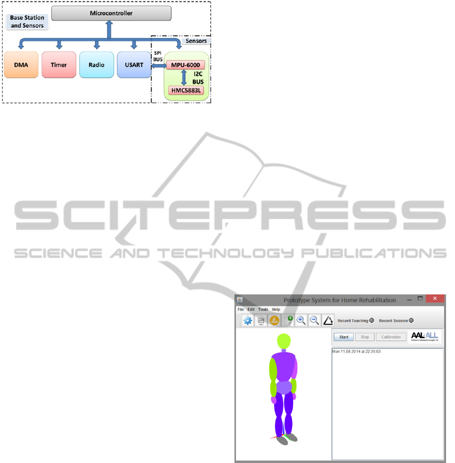
Figure 2: Base station and sensor architecture.
The Universal Synchronous Asynchronous
Receiver Transmitter (USART) and Radio
peripherals are controlled by the CC2530 with the
assistance of the Direct Memory Access (DMA)
subsystem. Some of the station base responsibilities
are the association of new sensor nodes into the
network, the allocation of time slots on the eLPRT
superframe for the nodes transmission, and the
network synchronization with the aid of periodic
beacons.
The information regarding the number of
readings of the sensors per superframe and the
transmission period is set by the user’s application.
In the sensor nodes, data messages containing the
readings of the 3-axis inertial, magnetic and
gyroscope sensors, temperature and battery level are
aggregated into a single message, according to the
number of readings per superframe. The sensor
information is collected through the serial peripheral
interface (SPI) bus and sent to the base station once
per superframe using the eLPRT protocol.
3.2 Sensor Node Prototype
Within the sensor prototype (Macedo et al., 2014),
powered by a 3.9 V/120 mAH, two sensors can be
found, the MPU-6000 Motion Processing Unit from
InvenSense, which has an embedded 3-axis MEMS
accelerometer, a 3-axis gyroscope (readings not used
at the moment) and a digital motion processor
(DMP) hardware accelerator engine with an
auxiliary I
2
C port that interfaces to a third party
digital sensor, such as a magnetometer. The
Honeywell 3-axis Digital Compass IC HMC5883L
is used in this prototype. More detailed information
about the sensors is described in (Macedo et al.,
2014).
3.3 PC Software
The system component with the greatest relevance to
the user is the PC application. This application
serves as a mediator between the users and the base
station; it can send commands and receive
information sent by the sensor nodes attached to the
body segments. Upon reception of the data from the
sensors, it calculates the angles of rotation and
presents the movement of the user’s body in real-
time on a 3D model of the human body.
One sensor node per monitored segment is
necessary to measure the movement, with three
degrees of freedom (DOF), expressed by the Euler
angles pitch, roll and yaw. The overall system was
designed to be as intuitive and easy to handle by the
user as possible. When compared to the previously
presented application (Macedo et al., 2014), this one
presents new features. The software provides means
to create learning files, to later compare movements;
and rehabilitation sessions files, where user
information and motion angles are stored. It also
introduces an assisted mode, where feedback
regarding the correctness of the movements is given
to the user. These session files can later be employed
to evaluate the user’s progress. A toolbar with the
most used buttons was also included, as well as
LEDs indicating that a learning session or
rehabilitation is being recorded. Figure 3 presents
the main window of the developed software.
Figure 3: Application interface.
4 SYSTEM EVALUATION
Advances have been made regarding the application
described in (Macedo et al., 2014). At this point, the
developed real-time 3D Java application, not only
evaluates the motion capture capabilities of the
system, but can also provide movement feedback.
The goal is to develop a home-based rehabilitation
system that, through constant monitoring of the
movement, is capable of interacting in real-time with
APersonalizedRehabilitationSystembasedonWirelessMotionCaptureSensors
223

the user. The purpose of this interaction is to assist
the user to perform the prescribed exercises
correctly. Poorly executed exercises can delay the
rehabilitation process, or even cause more damage.
Thus, the created application can serve as a
personalized exercise reference to a prescribed and
firstly assisted session, or even generic movement
body amplitudes; or merely serve to assess the
patient’s progress through the registration of
rehabilitation log sessions (if desired, both can be
performed simultaneously). This personalized
exercise reference system has three stages. The first
stage consists of a learning mode (section 4.1),
where it is showed to the patient how to perform the
exercise according to its specifications (special
needs he may have). This stage can be replaced for a
generic amplitude movement (correct patient
positioning and plane of motion for the moved body
joints), as the ones seen in (Braddom, 2006).
Amplitude movements, such as shoulder flexion and
extension, shoulder abduction, shoulder internal and
external rotation, elbow flexion and more. The
second stage (section 4.2) is characterized by the
personification of each patient movement into an
individual model. Finally, in the third stage (section
4.3), the patient can perform the prescribed exercises
at home, through the guidance of the assisted mode.
The learning mode and personalized model will
be further discussed in the sections 4.1 and 4.2
respectively. Section 4.3 will focus on the assisted
mode and a more detailed explanation of how this
assisted mode is achieved is described in section
4.3.1. Finally section 4.4 deals with the
rehabilitation sessions.
4.1 Learning Mode
Within this phase the patient will be taught, by
medical specialist, the correct movement that should
be replicated at home during the assisted mode. This
method aims to create a text file, which will serve,
later on, to learn and create a motion model of a
correctly performed exercise.
Each type of performed exercise creates a unique
motion model, depending on the type of exercise and
subject. Hence, every recorded movement is saved
on a text file, containing the angles between each
module present in the network and the planes of
motion of the global axis system and/or the
reference sensor node.
Within the learning file, a header (common to all
files) is created containing the learning session
number, transmission period (superframe duration),
number of samples per period, date of session and a
record of the angles saved to the file (the angle name
given below depend on the specific movement, in
this case arm):
#(angle chestTranversePlane
#chestCoronalPlane chestSagitalPlane
#armTranversePlane armCoronalPlane
#armSagitalPlane forearmTransversePlane
#
forearmCoronalPlane forearmSagitalPlane
#armOrientation forearmOrientation)
The angle mentioned in the header file it is the
angle made between two segments of the body.
Taking as an example the arm, the angle made
between the arm and the forearm. Chest angles with
the motion plane are set with the global axis system;
arm and forearm angles are set with chest as
reference.
armOrientation and
forearmOrientation are direction angles,
calculated with the chest reference. Further along
(Section 4.3.1), will explained with more detail how
these angles are calculated. Later these angles will
serve as a means to create the motion model to an
exercise. The process of creating a new learning file
is initiated by the user and/or the physiotherapist.
Also, this process is protected by a password in
order to prevent recording false movements. Every
new reading (correspondent angle calculation) from
the sensors represents a new line in the text file.
4.2 Personalized Motion Model
The goal of this phase is to obtain, for the individual
subject and for each exercise, a personalized model
of one motion cycle, which will serve as reference to
the assisted exercise phase (section 4.3). After
opening the file, a motion model is immediately
created. This motion model is not more than the
processing of the angles recorded into a text file
during the learning phase.
At this moment the application only deals with
uniform movements, that is, simple movements, as
the ones seen in (Braddom, 2006) like: shoulder
flexion and extension; shoulder abduction; elbow
flexion; hip flexion, knee flexion; hip abduction; hip
flexion, knee extension; knee flexion; hip internal
and external rotation. The current motion model uses
a global threshold system of maximum and
minimum limits that an angle can take with the
motion planes (global axis system and reference axis
system).
4.3 Assisted Mode
The replication of movement through the 3D model
of the human body is inherent to the application. It is
SENSORNETS2015-4thInternationalConferenceonSensorNetworks
224
as simple as attaching a sensor node in the body
segment which you want to reproduce the
movement. On the other hand, the creation of logs of
rehabilitation sessions and learning processes must
be initiated by the users. As opposed to these
processes, the assisted mode depends on the pre-
existence of a learning file, so that a motion model
can be created. This assisted mode consists in
comparing the performed motion to a stored
reference motion model of the same movement
(learning file). The result of this comparison is
translated to a visual feedback to the user. To start
the assisted mode, the user must first open the
correspondent learning file. After opening the file
and correspondent motion model creation, the
assisted mode and visual feedback can begin.
At home, when using the assisted mode, the
application should be able to inform the user
whether the movement performed previously with
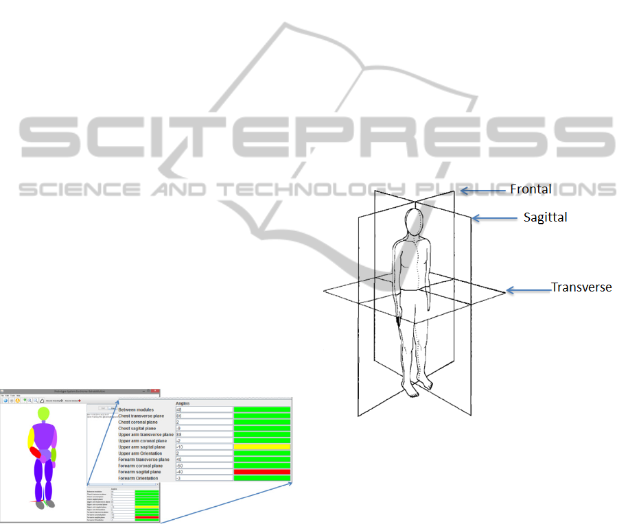
the caregiver, is being well executed. Figure 4
demonstrates the capabilities of the human 3D
model and application to provide feedback to the
user about the correctness of the movement. The
yellow and red colors are used to inform the user
that the allowed limits for the motion were exceeded
(yellow for the first threshold and red for the second
threshold). A detailed view of the angles that are
exceeding their thresholds is shown in the bottom
right side of the window, which presents the values
of the angles that the segment makes with each
motion plane. For this test, a learning file was
created, a simple flexion and extension of the right
arm, and then the user was asked to replicate the
previously taught movement.
Figure 4: Application interface in assisted mode.
4.3.1 Assessment of Range of Motion
In (Braddom, 2006), the author provides guidelines
to assess the efficacy of treatment procedures, to
determine the biomechanical cause of impairment
and to document the integrity of a joint range of
motion. According to the author, normal range of
motion (ROM) varies based on age, obesity, gender,
conditioning and genetics. Moreover, men have a
more limited range when compared to women,
depending on age and specific joint action. In order
to better assess the motion, passive ROM tests
should be performed by the examiner, thorough all
planes of motion, in a relaxed patient. On the other
hand, active ROM tests through all planes of motion,
performed by the patient without assistance from the
examiner, simultaneously evaluate muscle strength,
coordination of movement and functional ability.
The range of motion is measured with a universal
goniometer and should be performed prior to
strength testing. The developed system depicted here
can serve as a test goniometer to assess patient range
of motion and correctness of movement. The planes
of motion mentioned earlier consist in a division of
the human body into three cardinal planes, as shown
in Figure 5. The sagittal plane divides the body into
left and right halves. The frontal (coronal) plane
divides into anterior and posterior halves. Lastly, the
transverse plane divides the body into superior and
inferior parts.
Figure 5: Cardinal planes of motion (adapted from
Braddom, 2006).
The planes of motion are defined according the
coordinate system as follows: the transverse plane is
delimited by the x and y axis; the sagittal plane, by
the y and z axis; and the coronal is bounded by the x
and z axis. Using this global coordinate system, or
planes, defined by the axis position of a reference
module for other at the time of the movement, it is
possible to calculate the range of motion along the
planes. As an example the chest module can serve as
a reference for the arm modules. The coordinate
system used to calculate the three orientation angles
was the right-handed. The forward orientation of the
module is set to be along the y axis, with pitch
defining the rotation on the x axis (
∝
), the roll
APersonalizedRehabilitationSystembasedonWirelessMotionCaptureSensors
225
on the y axis (
) and yaw on the z axis (
),
according to equations 1, 2 and 3 respectively. After
the matrix multiplications (rotations), the final
matrix of the module’s orientation is found in
equation 4. This matrix is needed in case the
reference for the motion planes is another sensor
node; within this matrix the module’s axis can be
found. In those cases where the reference is the
global system, the axes are set to its origin: x axis to
[1 0 0]; y axis to [0 1 0]; and z axis to [0 0 1], equal
to the identity matrix.
The module’s orientation vector is given by
multiplying the final rotation matrix by its original
position [0 0 1], x axis, y axis and z axis
respectively.
∝
10 0
0 cos∝ sin∝
0 sin∝ cos∝
(1)
cos 0 sin
010
sin 0 cos
(2)
cos sin 0
sin cos 0
001
(3)
,∝,
∝
(4)
The orientation vector for the reference node
(sensor node or not) is given by the perpendicular
vector (normal vector) of the plane we want to
calculate. In other words, if we want to calculate the
angle between one module orientation vector and the
transversal plane, the orientation vector of that plane
is its z axis. The angle () between the two
orientation vectors is calculated using equation 5.
Therefore, the mentioned angle defines the angle
between a given module orientation vector and a
plane of motion (Dunn et al., 2011).
⋅
(5)
So far, the three planes of motion gave us three
angles to each module in relation to its reference(s),
but a fourth angle can be calculated, the torsion
angle. This angle reflects the difference between the
one module and its reference(s) direction. As an
example, if both modules are presented northwards,
the angle between them is zero. This angle must be
calculated with another module as reference,
because otherwise there would be no way to predict
the initial state (or direction) of the patient. The
plane used in the reference module is the sagittal,
and on the side of the other module it is used its
direction, y axis. The angle is calculated using
equation 5, with the y axis being considered the
orientation vector of the module; this value was
obtained in the final rotation matrix of the module.
The purpose of calculating all of these possible
angles, for each module, relative to the motion
planes, is to better assess the user’s performance.
4.4 Rehabilitation Session
This rehabilitation session mode was created in the
application in order to create session logs that can
later serve to gauge the patient’s progress during the
rehabilitation process. A new rehabilitation session
must be initiated by the user; only this way the
application will automatically create the new session
file.
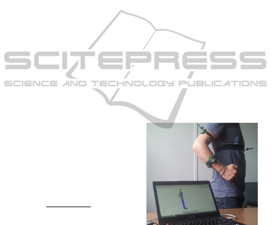
Several experiments were carried out to evaluate
the developed system. The one presented in this
paper had three sensor nodes attached to the body,
two of them on the right arm (upper arm and
forearm) and the other on the chest. The goal was to
verify the replication of the body movement in the
3D model present in the application and, at the same
time, produce a rehabilitation session file. Figure 6
and Figure 7 exemplify these experiments by means
of photographs taken while the movement was being
executed.
Figure 6: Right arm movement replication, first position.
Figure 8 presents the angle between the upper and
forearm along the time. The user was requested to
do a simple movement, flex and extend the arm,
multiple times. Information regarding the user name,
session number, type of rehabilitation, superframe
period, number of samples per superframe and date
of session can be seen on the left side. In the future,
more body angles will be added to the chart,
according to the performed movement and including
SENSORNETS2015-4thInternationalConferenceonSensorNetworks
226
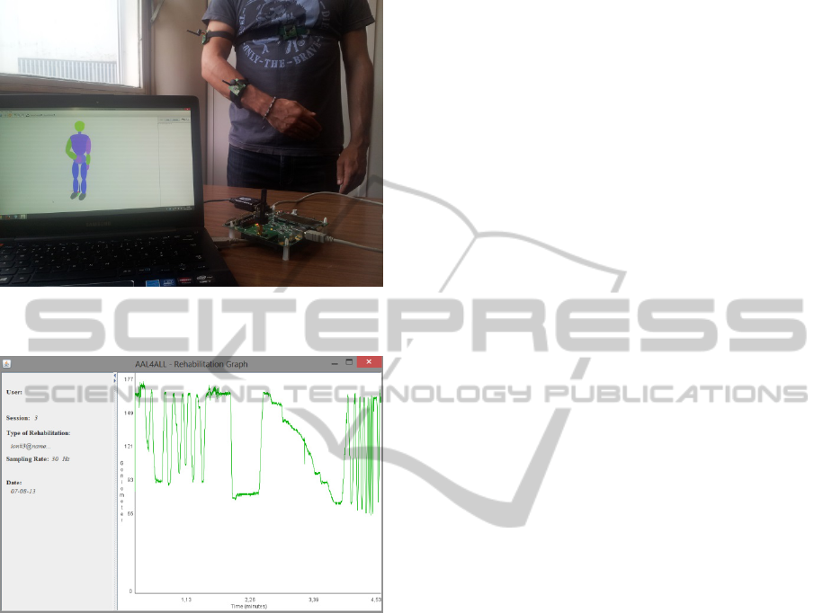
only the most relevant angles from those recorded
on the text file.
Figure 7: Right arm movement replication, second
position.
Figure 8: Chart of the angle of the articulation.
5 CONCLUSIONS
This paper outlines the design and development of a
wireless sensor network based on wearable and
easily placed inertial and magnetic sensors, which is
applied to monitoring of physical activities in
clinical settings and home environments. Such a
system can have tremendous application to
complement and enhance physical rehabilitation
procedures. An application capable of collecting
data from the sensors and present them in a real-time
3D model of a human body is under development,
focusing on the special case of assisting elderlies in
the practice of physiotherapy at home.
The main objective of this project consists in
developing a home-based rehabilitation system that,
through constant monitoring of the movement, is
capable of interacting in real-time with the user. The
purpose of this interaction is to assist the user to
perform the prescribed exercise correctly. The
rehabilitation process can be delayed or even cause
more damage if the exercise is poorly performed.
Therefore, this system can help medical specialists
to take into account physical limitations of the
patients in the preparation of physiotherapy sessions,
and to set well-defined objectives with regard to
patient outcomes.
The caregiver presence is not required during the
home-based sessions (assisted mode), but only in the
first session (learning mode). Unlike camera-based
systems, the patient can freely move anywhere under
the coverage of the WSN.
As future work, it is intended to create graph
sessions providing more useful information, such as
other meaningful angles, in order to create
rehabilitation session files that can better serve the
caregiver when assessing the patient’s progress.
Another feature under study is the compensation
of misplacement of the modules in the human body,
that is, if the sensor nodes are not attached correctly
to the chosen body segment, through the automatic
detection and correction of angle offsets with
relation to the correct position.
Studies are also being carried out in order to
improve the existing motion model. So far, a global
thresholds technique is being used, which places
limits to the angles which are used throughout the
movement and provides feedback to the user about
the correctness of his motion. Although this solution
results for simple movements, it is not able to
account for more complex movements. Therefore, a
new motion model based on local thresholds and
state machines is currently being implemented.
ACKNOWLEDGEMENTS
Project “AAL4ALL”, co-financed by the European
Community Fund FEDER through COMPETE –
Programa Operacional Factores de Competitividade
(POFC). FCT – Foundation for Science and
Technology – Lisbon, Portugal, through project
PEst-C/CTM/LA0025/2013.
REFERENCES
Afonso, J., Silva, H., Macedo, P., Rocha, L., 2011. An
Enhanced Reservation-Based MAC Protocol for IEEE
802.15.4 Networks. Sensors, Vol. 11, Issue 4, April
2011, pp. 3852-3873.
APersonalizedRehabilitationSystembasedonWirelessMotionCaptureSensors
227

Aminian, K., Najafi, B., 2004. Capturing human motion
using body-fixed sensors: outdoor measurement and
clinical applications. In Computer Animation and
Virtual Worlds, Volume 15, Issue 2, pp. 79-94.
Bergmann, J., Mayagoitia, R, Smith, I., 2009. A portable
system for collecting anatomical joint angles during
stair ascent: a comparison with an optical tracking
device. In Dynamic Medicine 2009, 8:3.
Braddom, R. L., 2006. Physical Medicine &
Rehabilitation. Third Edition.
Brander, V., Stulberg, S. D., 2006. Rehabilitation After
Hip and Knee Joint Replacement. An Experience and
Evidence-Based Approach to Care. In American
Journal of Physical Medicine & Rehabilitation, Vol.
85, No. 11 (Supplement): S98-118.
Cavallo, F., Aquilano, M., Odetti, L., Arvati, M.,
Carrozza, M.C., 2009. A first step toward a pervasive
and smart ZigBee sensor system for assistance and
rehabilitation. IEEE 11
th
International Conference on
Rehabilitation Robotics Kyoto International
Conference Center, Japan, June 23-26, 2009.
Dunn, F., Parberry, I., 2011. 3D Math Primer for Graphics
and Game Development. Second Edition pp. 141-143,
ISBN-13: 978-1-4398-6981-9, 2011.
Fuchsberger, M., 2008. Ambient Assisted Living: Elderly
People’s Needs and How to face Them. In
Proceedings of the 1
st
ACM international workshop on
Semantic ambient media experiences.
Hadjidj, A., Souil, M., Bouadballah, A., Challal, Y.,
Owen, H., 2012. Wireless sensor networks for
rehabilitation applications: Challenges and
opportunities. In Journal of Network and Computer
Applications.
Hamel, M., Fontaine, R., Boissy, P., 2008. In-Home
Telerehabilitation for Geriatric Patients. IEEE
Engineering in Medicine and Biology Magazine.
July/August 2008.
IEEE Std 802.15.4-2006, Part 15.4: Wireless Medium
Access Control (MAC) and Physical Layer (PHY)
Specifications for Low-Rate Wireless Personal Area
Networks (WPANs), September 2006.
Instituto Nacional de Estatística, Statistics Portugal, 2014.
Resident population in Portugal with a decreasing and
aging trend. Press release, 10 July 2014.
Kleinberger, T., Becker, M., Ras, E., Holzinger, A., 2007.
Ambient Intelligence in Assisted Living: Enable
Elderly People to Handle Future Interfaces. In 4
th
International Conference on Universal Access in
Huma-Computer Interaction, UAHCI.
Lin, J., Kulic, D., 2012. Human pose recovry using
wireless inertial measurement units. In Physiologial
Measurement, Volume 33, Number 12, 2012.
Linz, K., Stula, S., 2012. Demographic change in Europe –
An Overview. Working Paper No. 4 of the
Observatory for Sociopolitical Developments in
Europe.
Lu, T., Liu, H., Chen, R., Chen, Y., 2013. Motion-
Sensisng Based Management System for Smart
Context-Awareness Rehabilitation Healthcare. In
Advances in Internet of Things, 2013, 3, 1-7.
Macedo, P., Afonso, J. A., Rocha, L. A., Simões, R., 2014.
A Telerehabilitation System Based on Wireless
Motion Capture Sensors. International Conference on
physiological Computing Systems, 7-9 January, 2014.
Nitz, J. C., Hourigan, S. R., 2004. Physiotherapy Practice
in Residential Aged Care. ISBN 0 7506 8772 X.
O’Leary, K., UW Health Sports Medicine physician
group, 2011. Rehabilitation Guidelines for Surface
Replacement Arthroplasty (SRA). University of
Winsconsin Sports Medicine.
Stula, S., 2012. Living in Old Age in Europe – Current
Developments and Challenges. Working Paper No. 7
of the Observatory for Sociopolitical Developments in
Europe.
Sun, H., De Florio, V., Gui, N., Blondia, C., 2009.
Promises and Challenges of Ambient Assisted Living
Systems. In Information Technology: New
Generations. ITNG’09.
Texas Instruments, “CC2530 data Sheet” April 2009.
Retrieved from http://www.ti.com.
SENSORNETS2015-4thInternationalConferenceonSensorNetworks
228
