
RA2DL: New Flexible Solution for Adaptive AADL-based Control
Components
Farid Adaili
1,2,3
, Olfa Mosbahi
1
, Mohamed Khalgui
1
and Samia Bouzefrane
3
1
LISI Laboratory, National Institute of Applied Sciences and Technology, University of Carthage, Carthage, Tunisia
2
Tunisia Polytechnic School, University of Carthage, Carthage, Tunisia
3
Conservatoire National des Arts et M
´
etiers, Paris, France
Keywords:
Control System, Component, AADL, Reconfiguration, Modelling, Verification, Simulation, Radar.
Abstract:
The paper deals with adaptive component-based control systems following the Architecture Analysis and
Design Language (denoted by AADL). A system is assumed to be a network of software and hardware AADL
components that share the control of corresponding physical processes. A component is composed of a set
of algorithms encoding the control after any reception of external events and data signals. The termination of
execution is generally done with the emission of data and event signals to remote components. According to
various evolutions in environment, the system is required to be dynamically reconfigured at run-time to adapt
its control functions. We are interested in local reconfigurations ofr components dealing with the activation-
deactivation-update of algorithms and/or data-event inputs and outputs. We propose RA2DL as a solution
for reconfigurable AADL components, and define a hierarchical-based architecture to dynamically handle all
possible reconfiguration scenarios at run-time. We model and verify this solution and develop a tool for its
simulation by taking a real-case study as a running example.
1 INTRODUCTION
Embedded control systems Lozoya et al. (2008) con-
tinue to grow exponentially and has become critical
and complex under usually functional and temporal
constraints to be described in user requirements Peng
et al. (2008). According to various evolutions of the
environment due to incidents or also optimization of
performance, the system is required to be flexible by
adapting its behavior at run-time. Nevertheless, this
adaptation is not easy to be done since it should gen-
erally preserve the system safety while meeting its
constraints. Nowadays, two reconfiguration policies
exist, (i) static reconfiguration Angelov et al. (2005)
to be generally applied offline: (ii) and dynamic re-
configuration that can be applied at run-time. We
generally define two solutions for the second case:
manual reconfigurations to be applied by users at run-
time Rooker et al. (2007), and automatic reconfigu-
rations which are generally handled by software au-
tonomous agents Khalgui (2010). We are interested
in this paper in automatic reconfigurations of embed-
ded control systems. In order to reduce their devel-
opment and consequently their time to market, these
systems are based on the component-based approach
Zhu et al. (2012). A component is classically de-
fined as a software unit to be composed with oth-
ers in order to form the general control functions of
the whole system Lee and Kim (2004). Two fam-
ilies of components are proposed: the components
to be composed at run-time such as .Net Baudry
et al. (2002), COM-DCOM Luders (2003), Enter-
prise JavaBeans Liu et al. (2002), and the compo-
nents that should be composed off-line to check their
respect of functional and temporal constraints such
as IEC61499 Khalgui (2013), Metah Medvidovic and
Taylor (2000), ACME Seo et al. (2005), Rapide Palma
et al. (2006), Wright Allen et al. (1998), and AADL
Vergnaud et al. (2005). We are interested in this pa-
per in the AADL technology. AADL component is a
software unit to be encoded with a set of algorithms
that implement its control functions. Each algorithm
is activated by corresponding external event-data in-
puts, and generally produces the results of its execu-
tion on corresponding data-event outputs. It is well-
used in many industrial applications such as Avion-
ics Software Wang et al. (2011), Harmony System
Engineering (Harmony-SE) teng Zhang et al. (2012)
and M2M Prijic et al. (2010). We note that a rich
library is available today to develop applications in
247
Adaili F., Mosbahi O., Khalgui M. and Bouzefrane S..
RA2DL: New Flexible Solution for Adaptive AADL-based Control Components.
DOI: 10.5220/0005241202470258
In Proceedings of the 5th International Conference on Pervasive and Embedded Computing and Communication Systems (PECCS-2015), pages
247-258
ISBN: 978-989-758-084-0
Copyright
c
2015 SCITEPRESS (Science and Technology Publications, Lda.)

this technology. Nevertheless, these applications are
not flexible and cannot be adapted to their environ-
ment since SAE (Society of Automotive Engineers)
does not provide technical solutions for the possi-
ble adaptation of the system based on AADL com-
ponents at run-time. Moreover, no one in all related
works deal with the flexibility of AADL components.
We propose in this paper a new concept of reconfig-
urable AADL components to be named RA2DL that
allows (1) the activation-deactivation of algorithms at
run-time in order to adapt the control functions, (2)
the activation-deactivation of the corresponding data-
event inputs-outputs, (3) the reconfiguration of data
according to user requirements. In order to control
the complexity of the problem, we propose a control
unit-based architecture to apply local reconfiguration
scenarios in a RA2DL component.
RA2DL components is composed of two Mod-
ules: Controller Module that handles these recon-
figurations according to user requirements and also
the run-time evolution of the environment; and the
Controlled Module that represents all the different
services offered by the component. These services
are reconfigurable and implemented by different al-
gorithms to be activated by external event-data in-
puts before providing results on corresponding event-
data outputs. To cover all possible reconfiguration
forms while controlling their complexity, we spec-
ify the Controller Unit in three levels (i) Architecture
level that creates/removes or updates algorithms or in-
put/output data/event, (ii) Composition level that up-
dates compositions of their internal behaviors and (iii)
Data level that applies reconfigurations by data. The
Controller Module is modelled by Nested State Ma-
chines where states of a machine correspond to other
state machines. We use the well-known environment
UPPAAL (Bengtsson et al., 1996) to model and verify
the correctness of RA2DL components. The paper’s
contribution is applied to a case study of a radar sys-
tem that will be followed as a running example. This
system is deployed on an Arduino microcontroller,
and a tool named RA2DL tool is developed in our LISI
Lab at University of Carthage in Tunisia to implement
and simulate this case study.
We present in the next section the Architecture
Analysis and Design Language (AADL), and define
in Section 3 the case study of the radar system. Sec-
tion 4 proposes the concept of RA2DL, and Section
5 defines the modelling and verification where an
UPPAAL-based model checking is applied. We pro-
pose in Section 6 an implementation and simulation
of RA2DL tool and conclude the paper in section 7.
2 AADL
The Architecture Analysis and Design Language
(AADL) is an architecture description language used
to model the software and hardware architecture of an
embedded, real-time system Yang et al. (2012). Due
to its emphasis on the embedded domain, AADL con-
tains constructs for modeling both software and hard-
ware components (with the hardware components
named ”execution platform” components within the
standard). This architecture model can then be used
either as a design documentation, for analyses or for
code generation Within the AADL, a component is
characterized by its identity (a unique name and run-
time essence), possible interfaces with other compo-
nents, distinguishing properties (critical characteris-
tics of a component within its architectural context),
and subcomponents and their interactions.
AADL defines several categories of components,
divided into three categories:
1. Software Components: (i) Data: represent data
structures which can be stored or exchanged be-
tween components, (ii) Sub-programs: represent
fragments of executable sequence codes, such as
call-return and calls-on methods, (iii) Process: de-
fines memory spaces in which threads are run-
ning, (iv) Threads: active components that can ex-
ecute concurrently and be organized into thread
groups. They can be compared with light pro-
cesses as defined in the operating systems, (v)
thread group: component abstractions for log-
ically organizing threads, data, and groups of
thread components within a process,
2. Hardware Components: (i)Processor:schedules
and executes threads, (ii) Memory:stores code and
data, (iii) Bus: interconnects processors, memory,
and devices, (iv) Device: represents sensors, actu-
ators, or other components that interface with the
external environment,
3. System:design elements that enable the integra-
tion of other components into distinct units within
the architecture
AADL participates in several industrial applica-
tions such us avionics industry, Wang et al. (2011),
transport system Perseil et al. (2011), Harmony Sys-
tem Engineering (Harmony-SE) teng Zhang et al.
(2012), M2M (Machine-to-Machine) platform Prijic
et al. (2010), ASSERT project
3
Aniche et al. (2013).
We are interested in this technology because it has
useful advantages: AADL offers the possibility to de-
scribe the complete hardware/software architecture of
embedded control systems, it responds to architec-
tural constraints and can represent multi-modal sys-
PECCS2015-5thInternationalConferenceonPervasiveandEmbeddedComputingandCommunicationSystems
248

tems. AADL Standard prescribes the rules for activa-
tion and deactivation of components during a mode
switch, and a rich library is available today push-
ing to reuse applications based on AADL. Nowadays,
various books deal with this language. Various so-
phisticated tools are completely deployed according
to this technology: Stood Gaudel et al. (2013) also
introduces some methodological features to facilitate
the operational use of the AADL within industrial
projects, OSATE Kerboeuf et al. (2010) targets both
end users and tool developers. The former provides a
complete textual editor for AADL and a set of simple
analysis tools while the latter provides a full support
for the AADL meta-model on an Eclipse platform.
TOPCASED Pontisso and Chemouil (2006) is a soft-
ware environment primarily dedicated to the realiza-
tion of critical embedded systems including hardware
and/or software. ADes Tilman (2005) makes possible
the evaluation and analysis of the behavior of a sys-
tem during its specification with AADL, for instance
by helping in the choice of dimensioning parameters:
what will happen if we enlarge an execution time?
if we change a deadline? if we bind a task on an-
other processor?, Ocarina Zalila et al. (2008) is an
AADL tool that generates codes from AADL mod-
els. It runs on Linux, Mac OS X, Windows and So-
laris. ADELE Liu and Gluch (2009) has been created
to provide new versions of ADELE editor and also
Osate2 feature. Cheddar Gharbi et al. (2013) is a free
real-time scheduling tool. Although these tools are
useful, they do not provide solutions to develop flex-
ible AADL components for adaptive embedded sys-
tems. We mean by flexibility the facility to change the
behavior of a component according to user require-
ments and evolution of the environment. The cur-
rent paper proposes new solutions to allow reconfig-
urable AADL components called RA2DL which are
assumed to be adaptive at run-time according to user
requirements.
3 CASE STUDY: AADL-BASED
COMPONENTS FOR A RADAR
SYSTEM
We use as a running example in the current paper an
AADL-based radar represented by the STOOD tool
Dissaux (2004) as shown in Figure 1. As described
in Hugues and Singhoff (2009) and detailed as an
archive of Ocarina
1
, the radar is composed of the
following AADL components: (A) Hardware com-
ponents represented by (i) an Antenna component
1
http://aadl.telecom-paristech.fr
which is a device that simulates the radar environ-
ment, (ii) Processor component which is a part of the
execution platform, (iii) Memory component which
hosts the address spaces, (iv) Bus component that en-
sures the communication between the antenna and the
main process stored in memory, (v) Motor component
which is a device to rotate constantly the antenna and
returns the angle. (B) Software components assigned
to the processing component which is composed of
the following threads:
transmitter → angle controller → receiver →
analyser → display.
Where: (i) transmitter: a thread that sends the
radar signals to the antenna, (ii) angle controller: a
thread that computes the angle of the radar, (iii) re-
ceiver: a thread that receives any information from
the antenna, (iv) analyser: a thread that compares the
transmitted and received signals to perform the de-
tection, localization and identification of objects, fi-
nally (v) display: a thread that displays the objects on
the radar screen. The processing component has two
data inputs: (i)get angle: from the motor position,
and (ii) receive pulse: from the target detected object.
It has also two event outputs: (i) to screen , and (ii)
send pulse. Each internal thread has also data/event
inputs and outputs to support its interaction with re-
mote threads. The reader can find more details on this
radar in Hugues and Singhoff (2009). Although this
system is well-tested, it lacks any possible flexibil-
ity that can adapt its behavior at run-time when faults
occur, or when the radar environment evolved and re-
quires useful changes in the system’s behavior. This
flexibility is well-required for modern systems and
represents a new challenge for the radar case study.
Let us expose some reconfiguration scenarios that can
adapt the radar to its environment at run-time. Let us
suppose that the radar sends M pulses and detects N
objects at a particular time. Let us denote also by (i)
p
i
the i −th pulse (i ∈ [1,M]) to be sent from the an-
tenna with a frequency f
i
, (ii) O
j
the j −th ( j ∈ [1, N])
detected object from the radar. It is characterized by a
direction r
i
, a distance d
i
from the radar, and a surface
s
i
, (iii) C is a radar static parameter to be used for the
processing of areas in m
2
. It is equal to H Res if the
radar runs with a high resolution, otherwise L Res if
with low resolution, (iv) condition weather a boolean
parameter which is equal to 0 when the weather is bad
(snowing or running), and (v) wind speed which rep-
resents the wind speed. We assume that the radar has
two motors M1 and M2 to rotate the antenna with two
speeds according to the wind speed. Each motor is
controlled by a corresponding software AADL com-
ponent. We assume in the current paper that we have
two threads allowing the emission of pulses with two
RA2DL:NewFlexibleSolutionforAdaptiveAADL-basedControlComponents
249

periods according to the weather conditions: the first
sends the pulses each 6 ms whereas the second each 2
ms. We note that the calculation of the angle can be
done before the reception of signals or also after that
if we want to optimize the performance of the radar.
The calculation of the angle before the reception of
signals is done when the traffic is low, otherwise it
should be done each time a pulse is sent from the an-
tenna.
1. Reconfiguration 1. If there exists an object O
j
( j ∈ [1,N]) such that s
j
< C, Then the process-
ing component reconfigures the parameter C from
L Res to H Res to allow a possible detection of
the object,
2. Reconfiguration 2. If condition weather == 1,
Then the pulses are periodically sent from the an-
tenna by a thread EV T 1 each 6 ms,
3. Reconfiguration 3. If condition weather == 0,
Then the pulses are periodically sent from the an-
tenna by a thread EV T 2 each 2 ms,
4. Reconfiguration 4. If wind speed > 100 km/h,
Then the first radar motor M1 rotates 45 tr/mn.
We assume in this case that a particular software
AADL component Rotat1 is executed to control
the first motor,
5. Reconfiguration 5. If wind
speed < 100 km/h,
Then the second radar motor M2 rotates 30
tr/mn. We assume in this case that a second
software AADL component Rotat2 is executed to
control the second motor.
Although AADL is a well-expressive language,
it lacks useful technical solutions for the reconfigu-
ration of hardware and software components at run-
time. We propose in this paper to enrich this impor-
tant language with new solutions in order to allow
more flexible components that can be reconfigured at
run-time. We focus in this paper on the reconfigu-
ration of the AADL software Pocessing Component
which includes a set of sub-components (algorithms).
4 RA2DL: RECONFIGURATION
OF AADL
4.1 Motivation: Reconfiguration Forms
We define in this section a new concept named
RA2DL as a solution for reconfigurable AADL com-
ponents where the interface of the AADL component
contains data/event inputs and outputs supporting in-
teractions with the environment. Events are respon-
sible for the activation of the algorithms while data
contain valued information of the AADL component.
RA2DL is proposed in the current paper to adapt the
AADL to its environment at run-time.
Throughout our study, we concentrate on three hi-
erarchical reconfiguration levels that we present in the
following:
(i) Form 1: Architectural Reconfiguration: modi-
fies the component architecture when particular con-
ditions are met. This is done by adding new algo-
rithms, events and data or removing existing opera-
tions in the internal behaviors of the component. (ii)
Form 2: Compositional Reconfiguration: modifies the
composition of the internal components (algorithms)
for a given architecture. (iii) Form 3: Data Reconfigu-
ration: changes the values of variables without chang-
ing the component algorithms.
4.2 RA2DL Architecture
We define a new architecture for a RA2DL compo-
nent (to be denoted by Cmp). This architecture is
composed of a Controller module and a Controlled
module, where the first one is a set of reconfiguration
functions applied in RA2DL, and the second one is
a set of input/output events, algorithms, and data as
represented in the four reconfiguration modules RM
in Figure 2:
IEM (Input Events Module). This module processes
the reconfiguration of input events (IE) stored in
the IEDB database of input events. It defines and
activates at a particular time a subset of events to
execute the corresponding algorithms in RA2DL.
OEM (Output Events Module). This module pro-
cesses the reconfiguration of output events (OE)
stored in the OEDB database of output events. It
defines and activates at a particular time a subset
of events to be sent once the corresponding algo-
rithms finish their execution in RA2DL.
ALM (Algorithms Module). This module processes
the reconfiguration of the active algorithms (ad-
dition or removal) at a particular time in order to
be coherent with active input and output events of
IEM and OEM. These algorithms are stored in
the ALDB database of algorithms.
DM (Data Module). This module processes the re-
configurations of data in RA2DL in coherence
with the rest of modules. It is stored the DDB
database of data values.
Note that each reconfiguration scenario applied by
IEM, OEM, ALM and DM defines the required sets of
input-output events that activate corresponding algo-
rithms of the component Cmp with well-defined val-
ues of data. A reconfiguration scenario defines a new
PECCS2015-5thInternationalConferenceonPervasiveandEmbeddedComputingandCommunicationSystems
250

Figure 1: Graphical AADL representation of a radar components Hugues and Singhoff (2009).
Figure 2: RA2DL Architecture.
execution model of Cmp to apply required services
according to user requirements and also the evolution
of the environment.
4.3 Formalization
We aim in this section to dynamically reconfigure an
AADL component. The goal is to adapt its behavior at
run-time to its environment according to well-defined
user requirements. The reconfiguration is assumed to
be encoded in three hierarchical software levels: (a)
Architecture Level (to be denoted by AL), (b) Com-
position Level (to be denoted by CL), and (c) Data
Level (to be denoted by DL).
We define in AL, all the possible architectures that
can implement the AADL component at run-time. An
architecture in AL is a set of algorithms that per-
form control activities. A reconfiguration scenario
can change the software architecture of the AADL
component by adding or also removing algorithms.
For each architecture in AL, we need to define an
execution model of the corresponding algorithms. A
composition is then defined in CL to affect a priority
to each algorithm. For each architecture and for each
composition of the corresponding algorithm, we de-
fine also in Data level, all the possible corresponding
values of data to be handled at runtime. Thanks to this
hierarchical structure, the reconfiguration can handle
all possible reconfiguration scenarios of an AADL
component.
We formalize the new RA2DL component by:
Cmp= (β,R)
Where β is Controlled Module of RA2DL to be
described in the next section, and R is the Controller
Module which is described in the three following lev-
els:
4.3.1 First Level: Architectural Level (AL)
Deals with the changes of the architecture of the
RA2DL component when particular conditions are
satisfied. In this case, it is possible to add, remove
or also change the internal behavior of the compo-
nent in IEM, OEM,ALM and DM. We denote by
Ψ
Cmp
the big set in ALDB of all the possible algo-
rithms involved in the different implementations of
the component Cmp, which is implemented at any
particular time t by a subset ξ
Cmp
that represents the
set of algorithms involved in a particular implementa-
tion ξ
Cmp
⊆ Ψ
Cmp
. We model the architectural level
AL by a finite state machine S
AL
such that each state
of S
AL
corresponds to a particular implementation of
IEM,OEM,ALM and DM.
RA2DL:NewFlexibleSolutionforAdaptiveAADL-basedControlComponents
251

S
AL
= (Ψ
Cmp
, O, δ) , where:
O is a set of n states in S
AL
(O={ S
i
AL
| i ∈ 1..n } ),
δ is a state-transition function Ψ
Cmp
x O → Ψ
Cmp
x
O.
The reconfigurataion in this level is supported by the
Architectural Controller AC.
Running Example. We distinguish three architec-
tures of RA2DL in the radar system as depicted in
Figure 3
First architecture : when the weather is perfect,
(IEM = condition weather == 1), then we im-
plement the RA2DL according to the first archi-
tecture (ASM1).
Second architecture: when the weather is imper-
fect (IEM = condition weather == 0 and DM =
wind speed < 100 km/h), then we implement
the RA2DL according to the second architecture
ASM2.
Third architecture: when the weather is per-
fect and the wind speed is high ( IEM =
condition weather == 0 and DM = wind speed
> 100 km/h), then we implement the RA2DL ac-
cording to the third architecture ASM3.
Figure 3: First Architectural Level of RA2DL.
4.3.2 Second Level: Composition Level (CL)
This level keeps the same architecture in Cmp but just
changes the composition of algorithms, input-output
events in order to adapt the component to its environ-
ment. It is formalized by different Composition State
Machines CSM, such that each one CSM corresponds
to a particular state in the Architecture Level S
AL
. For
each state S
i
AL
in S
AL
, we define in the second hierar-
chical level (Composition Level CL) a particular state
machine to be denoted by S
i
CL
. Each state in S
i, j
CL
in
S
i
CL
defines a particular composition of the subset of
algorithms and input-output events. This composition
affects a priority to each algorithm in order to get a
deterministic execution model of the AADL compo-
nent Cmp. We denote by Γ(δ
Cmp
) the set of all pos-
sible execution models of algorithms of δ
Cmp
at the
composition Level.
S
CL
= (Γ(δ
Cmp
), P, γ) , where:
P is a set of m composition states in S
CL
(P= { S
i
CL
|
i ∈ 1..m } ),
γ is a state-transition function Γ(δ
Cmp
) x P→
Γ(δ
Cmp
) xP.
The reconfiguration in this level is supported by
the Composition Controller CC.
Running Example. We distinguish two compositions
in the radar system for the first architecture (ASM1):
the calculation of the angle can be done before or af-
ter the reception of signals (Figure 4). In this case, the
component has two compositions CSM1 and CSM2
such that each one is characterized by the time inter-
vals T
1
= 20seconds and T
2
= 60second.
Figure 4: Composition of ASM1
4.3.3 Third Level: Data level (DL)
A reconfiguration scenario R
i, j
CL
at Composition Level
CL, is a transition from a state S
i
CL
to another state S
i
CL
of S
CL
. The reconfiguration of the AADL component
Cmp at the third hierarchical level DL corresponds to
the update of data. We define for each state S
i
AL
of
S
AL
and for each state S
j
CL
of S
CL
a new state machine
S
DL
where each state corresponds to new values to
be affected to data belonging to µ
Cmp
under the com-
position S
i
CL
. Let Γ(µ
Cmp
) be the set of all possible
values of data under the composition S
j
CL
.
This level deals with the light reconfiguration of
data of the RA2DL component. It is formalized by a
set of Data State Machines where each state of them
corresponds to particular values of data. We define for
each state S
i
AL
of S
AL
and for each state S
i, j
CL
of S
i
CL
a
new state machine S
i, j,k
DL
where each state corresponds
to new values of data.
S
DL
= (Γ(µ
Cmp
), Q, ϑ) , where:
Q is a set of k composition states in S
DL
(Q={ S
i
DL
|
i ∈ 1..k } ),
PECCS2015-5thInternationalConferenceonPervasiveandEmbeddedComputingandCommunicationSystems
252

ϑ is a state-transition function Γ(µ
Cmp
) x Q →
Γ(µ
Cmp
) xQ.
The reconfiguration in this level is supported by
the Data Controller DC.
Running Example. In the radar system, if the
weather problem occurs at run-time, we have to
change the value of the parameter C in DM from
L Res (DSM1) to H Res (DSM2). In this case, we will
not be interested in any performance improvement but
in the rescue of the whole system to guarantee a min-
imal level of safety.
Finally, this classification covers all possible re-
configuration forms to dynamically adapt the RA2DL
component to the evolution in the environment ac-
cording to user requirements.
4.4 RA2DL Behaviors
To analyze the Controlled Module (β) of a RA2DL,
we characterize the corresponding algorithms by
worst (resp, Best) case execution times WCET ’s
(resp, BCET ). Moreover, we consider that output
events can be simultaneously sent or in exclusion
according to user requirements. To validate the
temporal behavior of a RA2DL component, we
only focus on input events. We assume, in the rest
of this paper, a complete synchronization between
events and data. Indeed, when an event occurs in
the corresponding input, all the associated data occur
at the same time in the corresponding inputs. The
different reconfiguration scenarios applied by the
different controllers, define all possible behaviors in
the β Controlled Module. In this work, we specify
these behaviors by a unique Behavior State Machine
(denoted by BSM) where each state corresponds to a
particular behavior of the RA2DL component.
Running Example. We specify in Figure 5 the dif-
ferent behaviors of the controlled part that we can
follow for all reconfigurations scenarios. We distin-
guish five branches of different behaviors. Branch 1
specifies the system behavior when Reconfiguration 1
is applied (e.g s
j
< C), Branch 2 specifies the sys-
tem behavior when Reconfiguration 2 is applied (e.g
condition weather == 1), Branch 3 specifies the sys-
tem behavior when Reconfiguration 3 is applied (e.g
condition weather == 0). Branch 4 specifies the sys-
tem behavior when Reconfiguration 4 is applied (e.g
wind speed > 100 km/h), and Branch5 specifies the
system behavior when the 4Reconfiguration 5 or (e.g
wind speed < 100 km/h) is applied.
5 MODELLING AND
VERIFICATION OF RA2DL
We propose in this section the modelling and verifica-
tion of RA2DL by using the UPPAAL toolBengtsson
et al. (1996). We model the Controller Module of
RA2DL by Nested State Machines such that the
Architectural Level is specified by ASM in which
each state corresponds to a particular architecture
of the component. Therefore, each transition of
ASM corresponds to an activation or desactivation
of algorithms and input-output events. A state of
ASM corresponds to a particular state machine in
the Composition Level denoted by CSM. This state
machine specifies all the composition forms of
algorithms and input-output events to be activated
in this architecture state of the first level. A state
of the Composition Level corresponds to a state
machine in the Data Level DSM that specifies all
possible values of data in the RA2DL component.
The Controller Unit applies automatically different
run-time reconfiguration scenarios such that each one
is denoted by Recon f iguration
i
where i ∈ [1.5].
Running Example. We present in Figure 6 the nested
state machines of RA2DL component in all levels of
reconfiguration. The ASM state machine is composed
of three states ASM1, ASM2 and ASM3 correspond-
ing respectively to the first architecture (i.e. per-
fect weather ), the second architecture (i.e. imper-
fect weadher) and the third architecture (i.e. per-
fect weather and wind speed is high). ASM1 cor-
responds in the second level to the nested state ma-
chine CSM1 which is composed of two states CSM11
and CSM12 that specify respectively the cases of per-
fect and imperfect weather. ASM2 corresponds to the
states CSM21,CSM22 that specify the wind speed,
and CSM23 and CSM24 that specify the weather
condition. ASM3 corresponds to the composition
CSM31,CSM32 for the combination between weather
and wind conditions. Finally DSM specifies the re-
configuration of the data processing component.
In the RA2DL, all the forms of reconfigurations
are given in Figure 7 which has five locations: Re-
configuration 1, Reconfiguration 2, Reconfiguration
3, Reconfiguration 4, and Reconfiguration 5 . We
initially start by Reconfiguration 1, which corre-
sponds to a processing component when the condi-
tion S
j < C is assumed. In this case, the process-
ing component reconfigures the parameter C from
L Res to H Res. If the weather situation is normal
then the condition condition weather == 0 is sat-
isfied. In this case, the radar system passes to the
RA2DL:NewFlexibleSolutionforAdaptiveAADL-basedControlComponents
253
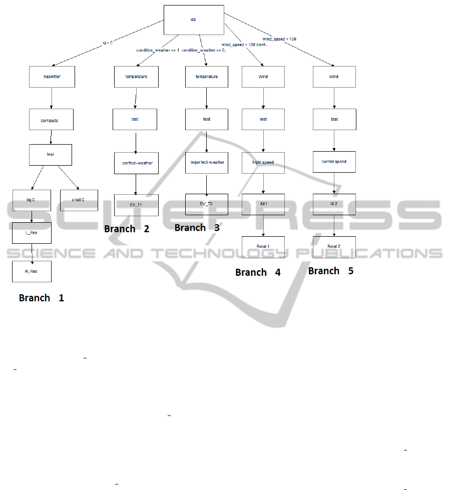
Figure 5: Behaviors of the controlled module.
state Recon f iguration3 after which the pulses are
periodically sent from the antenna component by a
thread component EV T 2 each 2ms in this state. If
wind speed > 100km/h then the radar system passes
to the state Recon f iguration4 where the first mo-
tor component M1 rotates by 45tr/mn and the com-
ponent Rotat1 is executed to control the first mo-
tor. Otherwise when the condition wind speed <
100km/h is satisfied then the radar passes to the
state Recon f iguration5 where the second motor com-
ponent M2 rotates in 30tr/mn and the component
Rotat2 is executed to control the second motor. The
same thing, is repeated for the Recon f iguration2
when the condition condition weather == 1 is sat-
isfied.
In Figure 6, we present the automata of the
controlled module describing the bevahior of the
radar system represented by algorithms, input-output
events/data. Figure 7 models all the reconfiguration
to be performed by the controller module.
We check the correctness of the system’s behavior
after any reconfiguration scenario in order to avoid
any unpredictable execution.
Running Example. In the assumed radar compo-
nent, we check simple reachability, safety, liveness
and deadlock-free properties. The simple reachabil-
ity properties are checked if a given location is reach-
able:
• P1= A[]RA2DL.(Reconfiguration2 or Reconfig-
uration3 or Reconfiguration4 or Reconfigura-
tion5): the radar system should work in all
weather conditions,
• P2= A[]RA2DL.Reconfiguration4.M1: the Mo-
tor M1 turns when the condition wind speed >
100km/h is satisfied,
• P3= A[]RA2DL.Reconfiguration5.M2: the Mo-
tor M2 turns when the condition wind speed <
100km/h is satisfied.
The following safety properties must be held for
all reachable states:
• P4= A[]RA2DL.Reconfiguration4.r=45: in bad
climate conditions the Motor M1 must rotate with
a well-defined speed equal to 45 tr/mn.
• P5= A[]RA2DL.Reconfiguration5.r=30: in good
climate conditions the Motor M2 must rotate with
a well-defined speed equal to 30 tr/mn.
The liveness properties are specified as follows:
PECCS2015-5thInternationalConferenceonPervasiveandEmbeddedComputingandCommunicationSystems
254

Figure 6: Nested State Machines of RA2DL.
Figure 7: Modeling of the Controller module.
• P6= A[] (RA2DL.ASM1⇒RA2DL.
Reconfiguration3.x <= 2) and
(RA2DL.ASM2⇒RA2DL.Reconfiguration2.x
<= 6): bounded Liveness: a RA2DL will re-
configure the sending signal in maximum within
2 seconds in Reconfiguration3 and 6 seconds in
Reconfiguration2.
• P7= RA2DL.Reconfiguration3⇒RA2DL.
Reconfiguration4: whenever wind speed >
100km/h, the corresponding M1 will eventually
turn.
• P8= RA2DL.Reconfiguration3⇒RA2DL.
Reconfiguration5: whenever a wind speed <
100km/h, the corresponding M2 will eventually
turn.
The deadlock-free property is described as fol-
lows:
• P9= A[]RA2DL not deadlock: the system is
deadlock-free.
The verification of these properties is summarized
in Table 1.
RA2DL:NewFlexibleSolutionforAdaptiveAADL-basedControlComponents
255

Table 1: Verification result.
Property Result Time (sec) Memory (Mo)
P1 Yes 16.37 4.45
P2 Yes 4.48 4.03
P3 Yes 12.20 4.20
P4 Yes 10.34 4.20
P5 Yes 3.44 4;03
P6 Yes 8.50 4.20
P7 Yes 13.16 4.45
P8 Yes 7.12 4.20
P9 Yes 4.23 4.03
6 SIMULATION
We present in this section the simulator RA2DLtool
and the radar system that we developed in LISI Labo-
ratory at INSAT Institute of University of Carthage in
Tunisia. First, we present some interfaces of the sim-
ulator RA2DLtool. Second we show a simulation of
the RA2DL-based radar system implemented in Ar-
duino Uno microcontroller with ATMega32 processor
(8 bits) and SRAM 2KB, the antenna is represented
by an ultrasound sensor hc-SR04 and the motor is rep-
resented by Servomoteur df05bb with a power sup-
ply of 160mA (4.8V), speed 0.17 seconds/60 degrees.
The implementation and simulation of the radar sys-
tem are represented in Figure 8.
Figure 8: Radar System.
The RA2DL tool offers the possibility to create all
reconfiguration scenarios of the RA2DL component
(addition,removal and update of algorithms, events
and data) when any weather problem occurs (Fig-
ure 9).
Running Example. In the radar system (Figure 11),
we assume that the perfect-weather mode is ap-
plied. To verify the interaction between the controller
Figure 9: Interface for Reconfiguration Architecture in
IEM.
Figure 10: Result after reconfiguration.
and controlled modules when a problem imperfect-
weather appears, we change the state of the rotor and
antenna component. Consequently, the AC decreases
or changes the time of sending the signals, angles and
rotations of the rotor. AC studies the feasibility of this
new reconfiguration in order to accept the composi-
tion change of the system. In this case, the AC con-
troller sends a final confirmation to officially apply
this new reconfiguration. The result of this reconfig-
uration is displayed on the screen of radar as in Fig-
ure 10.
The RA2DL is a solution for the run-time reconfigu-
ration of the AADL component in the radar system.
By this solution the AADL component has become
dynamic and flexible. None of the existing works
has treated the dynamic reconfiguration of the AADL
components as our method did.
PECCS2015-5thInternationalConferenceonPervasiveandEmbeddedComputingandCommunicationSystems
256
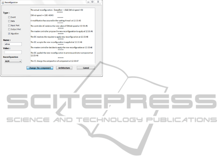
Figure 11: Example of reconfiguration.
7 CONCLUSION
The paper deals with new solutions for a required flex-
ibility of adaptive control systems. It is applied to a
radar system following the AADL language. We clas-
sify all possible reconfiguration scenarios of a compo-
nent into three forms: The first deals with the compo-
nent architecture, the second with the internal com-
position of algorithms as well as input-output events
and the third with the reconfiguration of data. We
propose a new concept named RA2DL to enrich the
AADL Language by adding the flexibility criterion
to its components. RA2DL is composed of a Con-
troller module that allows all forms of reconfigura-
tions, and a Controlled module that encodes all possi-
ble reconfigurable services to be offered by the com-
ponent. The Controller module is modelled by Nested
State Machines to control the complexity of the re-
configuration problem, whereas the Controlled mod-
ule is modelled by a multi-branches state machines
where each branch corresponds to a particular recon-
figuration scenario. We plan in the future works to
study the reconfiguration of several RA2DL compo-
nents that should be coherent after any reconfigura-
tion scenario to avoid any faults of interoperability.
This work will be extended for the reconfiguration of
distributed systems where new RA2DL components
should be defined to allow feasible and coherent dis-
tributed reconfigurations on different devices.
REFERENCES
Allen, R., Douence, R., and Garlan, D. (1998). Specifying
and analyzing dynamic software architectures.
Angelov, C., Sierszecki, K., and Marian, N. (2005). De-
sign models for reusable and reconfigurable state ma-
chines. In in L.T. Yang et al. (Eds.): Proc. of EUC
2005, LNCS 3824, pages 152–163.
Aniche, M., Oliva, G., and Gerosa, M. (2013). What do the
asserts in a unit test tell us about code quality? a study
on open source and industrial projects. In Software
Maintenance and Reengineering (CSMR), 2013 17th
European Conference on, pages 111–120.
Baudry, B., Fleurey, F., Jezequel, J.-M., and Le Traon,
Y. (2002). Automatic test case optimization using a
bacteriological adaptation model: application to .net
components. In Automated Software Engineering,
2002. Proceedings. ASE 2002. 17th IEEE Interna-
tional Conference on, pages 253–256.
Bengtsson, J., Larsen, K., Larsson, F., Pettersson, P., and Yi,
W. (1996). Uppaal; a tool suite for automatic verifica-
tion of real-time systems. pages 232–243, Secaucus,
NJ, USA. Springer-Verlag New York, Inc.
Dissaux, P. (2004). Using the aadl for mission critical soft-
ware development. 2nd European Congress ERTS,
Embedded Real Time Software.
Gaudel, V., Plantec, A., Singhoff, F., Hugues, J., Dissaux,
P., and Legrand, J. (2013). Enforcing software engi-
neering tools interoperability: An example with aadl
subsets. In Rapid System Prototyping (RSP), 2013 In-
ternational Symposium on, pages 59–65.
Gharbi, A., Khalgui, M., and Ben Ahmed, S. (2013).
The embedded control system through real-time task.
In Modeling, Simulation and Applied Optimization
(ICMSAO), 2013 5th International Conference on,
pages 1–8.
Hugues, J. and Singhoff, F. (2009). D
´
eveloppement de
syst
`
emes
`
a l’aide d’aadl- ocarina/cheddar. In Tutoriel
pr
´
esent
´
e
`
a l
´
ecole d’
´
et
´
e temps r
´
eel.
Kerboeuf, M., Plantec, A., Singhoff, F., Schach, A., and
Dissaux, P. (2010). Comparison of six ways to extend
the scope of cheddar to aadl v2 with osate. In En-
gineering of Complex Computer Systems (ICECCS),
2010 15th IEEE International Conference on, pages
367–372.
Khalgui, M. (2010). Nces-based modelling and ctl-based
verification of reconfigurable embedded control sys-
tems. Comput. Ind., 61(3):198–212.
Khalgui, M. (2013). Distributed reconfigurations of au-
tonomous iec61499 systems. ACM Trans. Embed.
Comput. Syst., 12(1):18:1–18:23.
Lee, J. and Kim, J.-S. (2004). A methodology for de-
veloping component-based software with generation
and assembly processes. In Advanced Communica-
tion Technology, 2004. The 6th International Confer-
ence on, volume 2, pages 696–699.
Liu, H. and Gluch, D. P. (2009). Formal verification of aadl
behavior models: A feasibility investigation. In Pro-
ceedings of the 47th Annual Southeast Regional Con-
ference, ACM-SE 47, pages 36:1–36:6, New York,
NY, USA. ACM.
Liu, Y., Gorton, I., Liu, A., and Chen, S. (2002). Evaluating
the scalability of enterprise javabeans technology. In
Software Engineering Conference, 2002. Ninth Asia-
Pacific, pages 74–83.
RA2DL:NewFlexibleSolutionforAdaptiveAADL-basedControlComponents
257

Lozoya, C., Velasco, M., and Marti, P. (2008). The one-
shot task model for robust real-time embedded control
systems. Industrial Informatics, IEEE Transactions
on, 4(3):164–174.
Luders, F. (2003). Adopting a software component model
in real-time systems development. In Software En-
gineering Workshop, 2003. Proceedings. 28th Annual
NASA Goddard, pages 114–119.
Medvidovic, N. and Taylor, R. N. (2000). A classification
and comparison framework for software architecture
description languages. IEEE Transactions on Soft-
ware Engineering, 26(1):70–93.
Palma, K., Eterovic, Y., and Murillo, J. M. (2006). Extend-
ing the rapide adl to specify aspect oriented software
architectures. In SEDE, pages 170–167.
Peng, Z., Ma, L., and Xia, F. (2008). A low-cost embed-
ded controller for complex control systems. In Em-
bedded and Ubiquitous Computing, 2008. EUC ’08.
IEEE/IFIP International Conference on, volume 1,
pages 23–29.
Perseil, I., Pautet, L., Rolland, J., Filali, M., Delanote,
D., Baelen, S., Joosen, W., Berbers, Y., Mallet, F.,
Bertrand, D., Faucou, S., Zitouni, A., Boufaida, M.,
Seinturier, L., Champeau, J., Abdoul, T., Feiler, P.,
Mraidha, C., and Gerard, S. (2011). An efficient
modeling and execution framework for complex sys-
tems development. In Engineering of Complex Com-
puter Systems (ICECCS), 2011 16th IEEE Interna-
tional Conference on, pages 317–331.
Pontisso, N. and Chemouil, D. (2006). Topcased combin-
ing formal methods with model-driven engineering. In
Automated Software Engineering, 2006. ASE ’06. 21st
IEEE/ACM International Conference on, pages 359–
360.
Prijic, A., Prijic, Z., Vuc-kovic, D., and Stanimirovic, A.
(2010). Aadl modeling of m2m terminal. In Micro-
electronics Proceedings (MIEL), 2010 27th Interna-
tional Conference on, pages 373–376.
Rooker, M. N., S
¨
under, C., Strasser, T., Zoitl, A., Hum-
mer, O., and Ebenhofer, G. (2007). Zero downtime re-
configuration of distributed automation systems: The
εcedac approach. In Proceedings of the 3rd
International Conference on Industrial Applications
of Holonic and Multi-Agent Systems: Holonic and
Multi-Agent Systems for Manufacturing, HoloMAS
’07, pages 326–337, Berlin, Heidelberg. Springer-
Verlag.
Seo, Y.-J., Song, Y.-J., and Jeong, H.-Y. (2005). Acme-
based connector interface considering component im-
portant factor. In SKG International Conference on
Semantics, Knowledge and Grid (SKG 2005), 27-29
November 2005, Beijing, China, page 54. IEEE Com-
puter Society.
teng Zhang, T., min Wu, J., Qi, L., and yu Xu, H. (2012).
Architecture analysis and design language amp; har-
mony system engineering process. In Digital Avionics
Systems Conference (DASC), 2012 IEEE/AIAA 31st,
pages 7D2–1–7D2–12.
Tilman, J.-F. (2005). Building tool suite for aadl. In Dis-
saux, P., Filali-Amine, M., Michel, P., and Vernadat,
F., editors, Architecture Description Languages, vol-
ume 176 of IFIP The International Federation for In-
formation Processing, pages 197–207. Springer US.
Vergnaud, T., Pautet, L., and Kordon, F. (2005). Using
the aadl to describe distributed applications from mid-
dleware to software components. In Proceedings of
the 10th Ada-Europe International Conference on Re-
liable Software Technologies, Ada-Europe’05, pages
67–78, Berlin, Heidelberg. Springer-Verlag.
Wang, Y., Ma, D., Zhao, Y., Zou, L., and Zhao, X. (2011).
An aadl-based modeling method for arinc653-based
avionics software. In Computer Software and Appli-
cations Conference (COMPSAC), 2011 IEEE 35th An-
nual, pages 224–229.
Yang, C., Dong, Y., Zhang, F., Ahmad, E., and Gu,
B. (2012). Formal semantics of aadl models with
machine-readable csp. Computer and Information
Science, ACIS International Conference on, 0:565–
571.
Zalila, B., Pautet, L., and Hugues, J. (2008). Towards
automatic middleware generation. In Object Ori-
ented Real-Time Distributed Computing (ISORC),
2008 11th IEEE International Symposium on, pages
221–228.
Zhu, L., Li, X., Ouyang, H., Wang, Y., Liu, W., and Shao,
K. (2012). Research on component-based approach
load modeling based on energy management system
and load control system. In Innovative Smart Grid
Technologies - Asia (ISGT Asia), 2012 IEEE, pages
1–6.
PECCS2015-5thInternationalConferenceonPervasiveandEmbeddedComputingandCommunicationSystems
258
