
Ubtl
UML Testing Profile based Testing Language
Johannes Iber, Nermin Kajtazovi´c, Andrea H¨oller, Tobias Rauter and Christian Kreiner
Institute for Technical Informatics, Graz University of Technology, Inffeldgasse 16, Graz, Austria
Keywords:
UML Testing Profile, UML, Textual Domain-Specific Language, Test Specification Language, Software
Testing, Model-Driven Development.
Abstract:
The continuous increase of software complexity is one of the major problems associated with the development
of today’s complex technical systems. In particular, for safety-critical systems, which usually require to be
thoroughly verified and validated, managing such a complexity is of high importance. To this end, industry is
utilizing Model-Driven Development (MDD) in many aspects of systems engineering, including verification
and validation activities. Until now many specifications and standards have been released by the MDD com-
munity to support those activities by putting models in focus. The general problem is, however, that applying
those specifications is often difficult, since they comprise a broader scope than usually required to solve spe-
cific problems. In this paper we propose a domain-specific language (DSL) that allows to specify tests from
the UML Testing Profile (UTP). The main contribution is that only particular aspects of UTP are captured,
thereby allowing the MDD process to be narrowed to specific needs, such as supporting code generation fa-
cilities for certain types of tests or even specific statements in tests. In the end we show the application of the
DSL using a simple example within a MDD process, and we report on performance of that process.
1 INTRODUCTION
Currently, many industrial sectors are confrontedwith
massive challenges originating from managing the
complexity of system engineering. The automotive
industry, for instance, has an annual increase rate
of software-implemented functions of about 30%.
This development is even higher for avionics systems
(Feiler et al., 2009), (Ebert and Jones, 2009) . In ad-
dition, the complexity is driven by several other di-
mensions, including the number of devices that run
software functions and the inter-connections among
those devices. Ultimately, in some sectors, several or-
ganizations are participating in the development, thus
raising additional issues related to system integration
(e.g., suppliers and manufacturers in the automotive
development landscape). This all poses a huge prob-
lem for verification and validation activities, since the
aforementioned class of systems needs to be rigor-
ously tested and quality-assured.
Model-driven Development (MDD) is a promis-
ing engineering discipline to address the challenges
mentioned above. Industry is currently utilizing
MDD in many aspects of the system lifecycle, by
putting models in focus of the development (BIT-
COM, 2008). To date many MDD products (i.e.,
meta-models, languages, tools, etc.) have been de-
veloped, to support the development of complex tech-
nical systems in various fields (Feiler et al., 2009). A
sub-set of these products (specifications) is tailored
to testing such systems, and allows developers to de-
fine and to synthesize various types of tests required
for their systems. One of these products is the UML
Testing Profile (UTP), which is a meta-model com-
monly used to specify and to synthesize tests based on
a computational model of UML (Object Management
Group (OMG), 2013). The test model in UTP pro-
vides a generic architecture tailored to perform var-
ious types of black-box tests, and allows UTP to be
used in general for embedded system engineering, as
shown in several studies (Baker et al., 2008), (Iyeng-
har et al., 2011).
Unfortunately, there are some issues, which make
the application of UTP within a well-known V-
model
1
cumbersome for test engineers. First, the rep-
resentation: the graphical notation of test suites is not
necessarily optimal for all types of tests within a V-
model.
For instance, module tests usually have a strong
1
A common lifecycle model for safety-critical systems
(Smith and Simpson, 2010)
99
Iber J., Kajtazovic N., Höller A., Rauter T. and Kreiner C..
Ubtl - UML Testing Profile based Testing Language.
DOI: 10.5220/0005241300990110
In Proceedings of the 3rd International Conference on Model-Driven Engineering and Software Development (MODELSWARD-2015), pages 99-110
ISBN: 978-989-758-083-3
Copyright
c
2015 SCITEPRESS (Science and Technology Publications, Lda.)

focus on a functional behaviour of a single module,
and capture just a portion of system behaviour (e.g.,
a software component). Such a test may consists of
many primitive statements, for example value assign-
ments, loops, and use of test data from external files.
In many cases, specifying such tests with textual no-
tation would be more practical for test engineers. Sec-
ond, the scope: UML, which is used to specify a
system under test in UTP, provides a large and com-
plex set of elements and features. The main problem
here is that the same concepts can be often defined
in UML in many different ways. This poses a chal-
lenge to synthesizing the concrete test code, because
explicit checks have to be performed in order to en-
sure that test engineers are prevented from specifying
tests which include fragments of UML that cannot be
technically synthesized.
In this paper, we propose a textual domain-
specific language (DSL) that allows to specify tests
from the UML Testing Profile (UTP) – UTP-based
Testing Language, Ubtl. The main contribution here
is that only particular aspects of UTP are captured,
thereby allowing the MDD process to be narrowed to
specific needs, such as supporting code generation fa-
cilities for certain types of tests or even specific state-
ments within tests for example. In response, using
the proposed DSL, the test engineer is constrained to
work with only a sub-set of UTP and UML features
for which the corresponding synthesis (code genera-
tion) functionality is provided. We report in the end
of the paper the applicability of DSL and its perfor-
mance within a MDD synthesis process.
The remainder of this paper is structured as fol-
lows: the next section provides a brief overview over
relevant related studies. In Section 3, the proposed
DSL (Ubtl) with the main language features is intro-
duced. Later, in Section 4, a use case demonstrating
the applicability of Ubtl is described. This section
further gives a short evaluation of performance of an
MDD process in which Ubtl is used. Finally, conclud-
ing remarks are given in Section 5.
2 RELATED WORK
In the following, we briefly summarize some relevant
studies that in particular focus on models and lan-
guages for testing complex technical systems.
One of the first, and most notable, models for
software and system testing is the UML Testing Pro-
file (UTP). UTP is standardized by the Object Man-
agement Group, (Object Management Group (OMG),
2013), and offers well-thought-out concepts for spec-
ifying test cases in UML (Object Management Group
(OMG), 2014). Although the underlying test model
is based on UML, UTP is not restricted to object-
oriented design. For instance, it has been used in the
context of resource-constrained real-time embedded
systems (Iyenghar et al., 2011), for testing web ap-
plications running in web browsers (Bagnato et al.,
2013) or for testing protocols (Kumar and Jasperneite,
2008). The key concept is the usage of UML classes,
tagged with the stereotype TestContext, as entry point
and container for test cases and optional test config-
uration, while the concrete test cases are specified as
UML interactions, which could be visualized for in-
stance as sequence diagrams. UTP is mainly used
with the graphical syntax of UML in order to spec-
ify the different parts of its elements and features.
As explained previously, UTP can be used on all lev-
els of the well-known V-Model, (Baker et al., 2008),
however, with some difficulties in modelling and code
synthesis.
UTP is strongly influenced by the Testing and Test
Control Notation version3 (TTCN-3), which is a DSL
similar to our Ubtl. However, the main difference be-
tween Ubtl and TTCN-3 is that TTCN-3 test cases are
meant to be used by the (domain-specific) standard-
ized test architecture, (ETSI, 2014b). It is not fore-
seen to translate a TTCN-3 test case to other test plat-
forms, for instance JUnit. Further, there is no stan-
dardized meta-model as an intermediate representa-
tion. A possible meta-model has been discussed by
(Schieferdecker and Din, 2004). However, it depends
on the tool vendors how the transformation is actu-
ally implemented and which programming languages
or platforms are supported.
Recently, the abstract syntax of the Test Descrip-
tion Language (TDL) has been released and stan-
dardized by ETSI, (ETSI, 2014a). TDL offers con-
cepts similar to UTP, but with a simpler meta-model
than UML. That limits the possible interpretations of
the concepts and semantics, which is a problem with
UML due to the complexity and different ways to
specify the same thing. Currently, there is an im-
plementation of the TDL meta-model based on the
Eclipse Modeling Framework (EMF, (Eclipse Foun-
dation, 2014c)), provided by ETSI, (ETSI, 2014a). It
is planned to standardize a concrete graphical syntax,
(Ulrich et al., 2014). Depending on the maturity of
TDL, i.e., if in the future the standardized meta-model
will be used by the industry more intensively and if
that results in emergingof several compatible tools, in
our opinion, it should be theoretically possible to au-
tomatically transform the generated UML/UTP mod-
els to TDL models.
In the literature, several other approachesfor spec-
ifying test cases have been proposed based on mod-
MODELSWARD2015-3rdInternationalConferenceonModel-DrivenEngineeringandSoftwareDevelopment
100
els (e.g. (Guduvan et al., 2013), (Arpaia et al., 2009),
(Hernandez et al., 2008), (Mews et al., 2012)). In
summary, these approaches havea common limitation
in their focus on a specific domain.
3 TEST SPECIFICATION
LANGUAGE – UBTL
In this section we introduce the proposed test speci-
fication language Ubtl. We first provide general in-
formation, to highlight some benefits of the language.
Then we show the possible uses of Ubtl, in terms of
different system configurations (e.g., IDE tools using
Ubtl, software and system models, etc.). Further, we
describe the realized software architecture and tools
used to compile Ubtl into concrete test cases. Finally,
we outline the main Ubtl elements and features, and
their mappings to UTP.
3.1 General
Ubtl offers a concise textual language. This textual
language is automatically compiled to UML in con-
junction with UTP. The benefit of using Ubtl for a
code generator is that related UML and UTP models
are always generated in the same way, i.e., they do
not contain UML and UTP concepts a code generator
cannot know beforehand, which in response simpli-
fies the development of code generation functionality.
Another advantage is that a test engineer, who is de-
veloping tests, is prevented from providing specifica-
tions that contain UML or UTP elements and features
not supported by the underlying code generators. For
this purpose, we provide a powerful Eclipse IDE for
Ubtl, which automatically validates whether the code
contains errors or missing properties. Further the IDE
provides content assist. For a test engineer it “feels”
like any other textual programming language.
3.2 Applications
As mentioned before, Ubtl code is always compiled
to UML models. We identify the following four ap-
plications of using Ubtl, from the viewpoint of a test
engineer, who is responsible for the definition of tests:
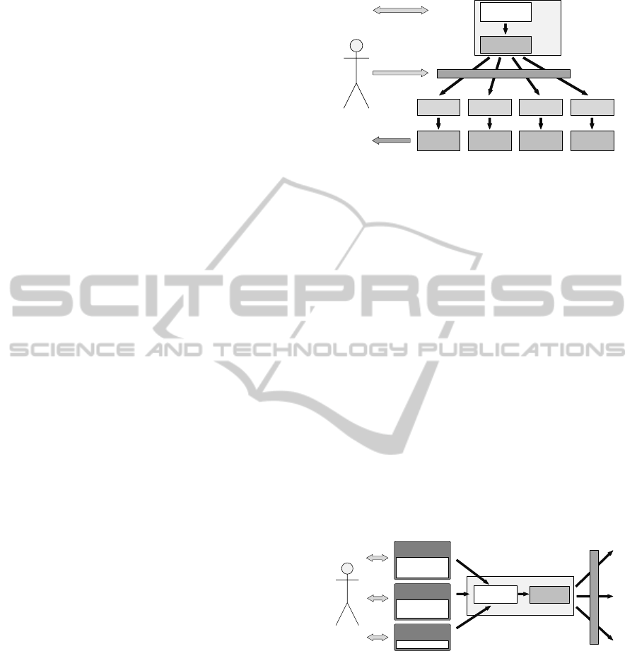
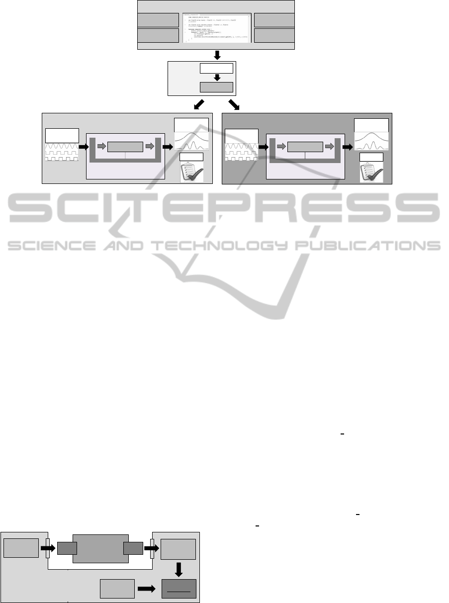
Application One: Figure 1 illustrates the first appli-
cation. A test engineer could specify test cases
with the Ubtl IDE inside Eclipse. After the Ubtl
compiler generates an UML model, a test engi-
neer can manipulate this model with a compatible
UML tool when necessary. Further, a test engi-
neer could trigger a code generator by using the
Ubtl IDE
C++ TTCN-3 ...XML
Generators
Test
Platform
Test
Platform
Test
Platform
Test
Platform
Test Engineer
Eclipse IDE
Results
Ubtl
(Textual DSL)
UML & UTP
Eclipse IDE /
Separated Tool
Figure 1: Ubtl application number one shows how a test en-
gineer could use the Ubtl IDE and different code generators.
UML model. This can happen inside Eclipse or
by leveraging an external tool which is compati-
ble to the Eclipse UML2 project. The generated
test cases can then be used by the target test envi-
ronment. These final test cases can be written in
any programming/testing language or format like
XML. In the last step the test engineer obtains the
test results of the final test platform. The benefit
of this approach is that the test engineer does not
have to know how the test cases have to look like
on the test platform. It is easy to support another
test environment, because just a different gener-
ator has to be developed. Another benefit is that
the test cases do not have to be written for every
platform over and over again. Even when there
is only one target platform, Ubtl might be useful.
For instance, when the platform expects an XML
file as a test input, it may be easier to specify it
with Ubtl rather than using XML.
Tool
Tool
Tool
Ubtl Compiler
Test Engineer
Model Based
Testing
Test Data
Generator
...
Ubtl
(Textual DSL)
UML & UTP
Generators
Figure 2: Ubtl application number 2 illustrates how Ubtl
could be leveraged by other tools.
Application Two: Ubtl could be used by other tools
(see Figure 2). For instance, a MDD tool could
specify resulting test cases or test data in Ubtl.
The advantage of this is that a tool does not have
to be aware of any dedicated platform except Ubtl.
It would be easy to add other test platforms, with-
out changing the front tools, because the corre-
sponding generators work with the UML model.
The Ubtl compiler can be leveragedas Javalibrary
in such an automatic process.
Application Three: Ubtl can be used in conjunction
Ubtl-UMLTestingProfilebasedTestingLanguage
101
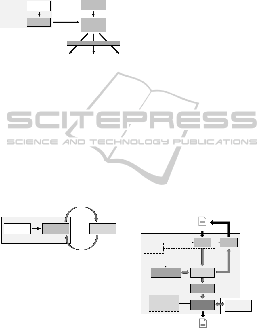
Ubtl IDE or Compiler
Software
model
Software
model with
test cases
Ubtl
(Textual DSL)
UML & UTP
transformation
Generators
Figure 3: Ubtl application number 3 shows how Ubtl could
be used in conjunction with existing models.
with models of software (see Figure 3). The test
cases would be specified with Ubtl, while the re-
sulting UML models could be transformed to test
cases part of the software model or specified in
the same modeling language like the model. The
advantage is that it could be easier to specify test
cases with Ubtl than with the target modeling lan-
guage. Ubtl may be simpler and easier to under-
stand. Ideally, the generators for the model of the
software could be reused for the test cases. This
variant could be especially useful for component-
based system engineering, where the interfaces of
components are often modeled, for instance with
the EAST-ADL UML2 profile, (Debruyne et al.,
2005). It would be easy to merge test cases and
components, and to synthesize concrete code and
test cases. Additionally, components could be
configured for testing purposes.
Ubtl IDE or Compiler
Ubtl
(Textual DSL)
UML & UTP Interpreter
Figure 4: Ubtl application number 4 illustrates how an in-
terpreter could use the resulting UML test cases.
Application Four: The resulting UML models do
not have to be used by code generators (see Fig-
ure 4). An interpreter could use an UML model as
input to stimulate test components or SUTs.
3.3 Software Architecture
We chose to develop Ubtl based on Java and Eclipse
projects because of two reasons: The Eclipse UML2
project and the Xtext project.
The Eclipse UML2 project (Eclipse Foundation,
2014d) is part of the Model Development Tools
project and implements the OMG UML 2.x meta-
model based on EMF. This project serves as the de
facto “reference implementation” of the specification
and was developed in collaboration with the specifi-
cation itself, (Gronback, 2009).
Several commercial or open-source UML mod-
eling tools can import/export Eclipse UML2 com-
patible models (Eclipse Foundation, 2014a). This
makes it a viable target for Ubtl. Prominent com-
mercial tools, which support Eclipse UML2, are for
instance Enterprise Architect, MagicDraw UML, and
IBM RSM/RSA.
Note that the graphical representations of UML
models can most of the time not be interchanged be-
tween modeling tools. For instance, a diagram (con-
crete syntax) drawn with Papyrus cannot be opened
by Enterprise Architect, but the underlying Eclipse
UML2 model (abstract syntax) is supported. In that
case a user would have to create a new diagram based
on the model with Enterprise Architect. This is an
issue which the OMG tries to solve with the UML
2.5 specification. Therefore we currently only gener-
ate Eclipse UML2 models, but no corresponding dia-
grams.
The Xtext project (Eclipse Foundation, 2014f) is
part of the Concrete Syntax Development project of
the Eclipse Modeling Project. It is a so called lan-
guage workbench, (Fowler, 2010), for designing tex-
tual languages, ranging from domain-specific lan-
guages to general-purpose languages. Concerning
Ubtl, we use an Xtext version based on version 2, to
to create a compiler.
Parser,
Linker
Ubtl Model
Serializer
Validator
Ubtl
Generator
.ubtl
Eclipse UML2
Java Libraries
.uml
Ubtl
Grammar
Ubtl Ecore
Meta-Model
transformed
to
utp.profile.uml
utptypes.uml
ubtl.uml
uses
Ubtl Compiler
Figure 5: Ubtl compiler architecture based on the Xtext
framework.
Figure 5 shows a simplified view of the relevant
MODELSWARD2015-3rdInternationalConferenceonModel-DrivenEngineeringandSoftwareDevelopment
102
components of the Ubtl compiler architecture. These
components are:
• The Ubtl Grammar, specified with the Xtext
grammar, is automatically transformed to the Ubtl
meta-model, parser, linker, and serializer.
• The Parser and Linker are responsible for read-
ing an Ubtl file and generating an Ubtl model. In-
ternally only the Ubtl model is used.
• The Serializer is responsible for transforming an
Ubtl model back to the textual representation.
• The Validator contains our restrictions of Ubtl.
• The Ubtl Generator is used to transform an Ubtl
model to an UML model. It leverages the Eclipse
UML2 libraries for this task. Additionally, it uses
the predefined UML models utp.profile.uml, utp-
types.uml, and ubtl.uml. We develop the genera-
tor, like all other parts, with the Xtend program-
ming language (Eclipse Foundation, 2014e).
All these compiler components seamlessly integrate
into the EMF environment and can be used sepa-
rately. The Ubtl IDE, which is automatically gener-
ated by the Xtext framework, also leverages the com-
piler components. A difference to the compiler is that
the IDE uses a different parser for the content assist,
which is in that case faster. We slightly customized
the IDE regarding the behavior of the content assist
and the visual appearance.
3.4 Language Elements
We separate the elements of the textual DSL into
declarations and definitions. Declarations are de-
fined by the test platform designers and may relate
to types, interfaces, and classes, which a code gen-
erator can know in advance. A test engineer on
the other hand can use these declarations to define
the actual test data, runtime objects, and test cases.
The declarations, definitions and test cases are always
transformed correctly to UML according to the UML
and UTP semantics. All these elements have to be
grouped in Ubtl packages, which are mapped to UML
packages. They can exist side-by-side in a package.
3.4.1 Declarations
Table 1 enumerates the available declarations of the
textual DSL and their mappings to UML. Exemplary
declarations can be found in Listing 1 which is part of
our presented use case.
The basic declarations, consisting of primitive, ar-
ray, and record, allow to restrict the possible usages
of corresponding Ubtl objects. Primitives offer to re-
strict that the name of a variable has to be specified
Table 1: Declarations in Ubtl and their mapping to UML.
Decl. Description Mapping
Primitive Primitive types are used to
declare types like integer,
float, string, and boolean.
Class realizing interface
Primitive.
Array Array types can be used to
define collections of prim-
itives, arrays, records, or
component and interface
types.
Class realizing interface
Array.
Record Record types are used to
define containers which
can hold several objects
of specified types as at-
tributes.
Class realizing interface
Record.
Interface Interfaces can hold at-
tributes and signatures. In-
terfaces can be used by
code generators, to iden-
tify what type a compo-
nent is.
Interface generalizing
from interface Compo-
nent.
SUT SUTs can hold attributes
and signatures. They rep-
resent the targets of test
cases.
Class realizing interface
Component. When a
SUT definition becomes
a property of a UML
test context, the property
is tagged with the UTP
stereotype SUT.
Test
Comp.
Test Components are sim-
ilar to SUT declarations.
They can be used to pro-
vide helper signatures or
represent mock objects.
Class realizing interface
Component and tagged
with the stereotype Test-
Component.
Test
Context
Test Contexts can disable
specific statements inside
a test case. They are nec-
essary to specify the name
of the UTP test context for
the Ubtl test cases.
Class tagged with the
stereotype TestContext.
when it is defined inline. Arrays can be restricted
to require names of contained primitive variables or
to not allow a reference to a variable multiple times.
All basic declarations have in common that they can
be configured to be referenceable only once, which
means that only one variable can refer to such a re-
stricted object.
Test Context allows to restrict the available state-
ments inside test cases (see Table 3).
All adjustable configurations/restrictions of the
Ubtl declarations, which are only relevant for Ubtl
code, are mapped to UML as comments. Therefore
it is possible to transform the UML models back to
Ubtl including the Ubtl specific configurations.
Signatures and attributes, specifiable by interface,
SUT, and test component, are mapped to UML op-
erations (without a corresponding interaction) and at-
tributes.
Ubtl-UMLTestingProfilebasedTestingLanguage
103
3.4.2 Definitions
Table 2 illustrates the available definitions, which can
implement declarations. Listing 2, part of the use
case, shows how definitions and statements are used.
Table 2: Definitions in Ubtl and their mapping to UML.
Def. Description Mapping
Variable Variable definitions are
runtime instances of
primitive, array, and
record declarations.
Instance specification.
Comp. Component definitions
represent runtime in-
stances of SUT and test
component declarations.
Instance specification. If a
signature is called, it also
becomes a property of a
test context which refers to
the instance specification.
Testcase Testcases hold the actual
test logic.
Interaction and operation
of test context according to
the UTP semantics. Test
context is generated on the
same package level.
Table 3 lists the statements which can be used in
test cases. With test components it is possible to pro-
vide signatures, which offer additional functionality,
for instance arithmetic, test platform or time related
operations. Code generators may have to know such
signatures beforehand.
Currently, we do not offer an Ubtl concept for
UTP test configurations.
4 USE CASE
In this section we show the application of Ubtl on
an exemplary use case. To this end, we introduce in
the following the MDD synthesis process, which uses
Ubtl to generate concrete test cases, and we describe
the use case (i.e., the system under test, SUT). In the
remainder of this section, we describe the essential
parts of that process more in detail, and finally, we
report on its performance.
4.1 Test Workflow
Figure 6 illustrates the MDD synthesis workflow,
which we have realized to evaluate Ubtl. This work-
flow is used in an industrial setup to conduct the func-
tional testing and qualification of component-based
safety-critical systems. The input to the workflow are
software componentsand test suites, specified in Ubtl.
In the compilation phase (the middle part of figure),
Ubtl test cases are translated into concrete tests, for
different target platforms. We show here two plat-
forms that we use for the evaluation, i.e., the embed-
Table 3: Statements which can be used inside a test case.
Statement Description and Mapping
Variable This is the same variable definition like in Table 2. The
difference is that the scope is narrowed to the test case.
Assignment We only allow to assign values to primitive variables.
Such variables can be part of records or arrays. This
concept is mapped to UML as call operation action on
a predefined assignment class.
Signature
Call
Signature calls are mapped to synchronous calls to op-
erations of component definitions which become part
of the enclosing test context. We do allow to assign a
return parameter, which is mapped to a reply message.
Set Verdict Set Verdict is mapped to UML according to the UTP
semantics.
Assertion Assertions allow to evaluate primitive variables. They
are mapped to call operation actions on a predefined
assertion class.
Loop Loops are used to repeat a sequence of statements for
a defined limit of iterations. They are mapped to com-
bined fragments with the interaction operator loop.
Foreach
Loop
Foreach loops allow to iterate through one or several
arrays of the same size. UML does not offer a ded-
icated concept for this kind of loop. Therefore, they
are mapped to combined fragments with the interac-
tion operator loop, but the specification of the guard
owns references to the instance specifications of the
foreach variables and arrays as operands. The name of
the fragment is foreach.
If Else If statements can only use primitive variables. They
are mapped to combined fragments with the interac-
tion operator alt.
Log Log statements are mapped according to the UTP se-
mantics.
ded ARM system (ARM9), and QEMU ARM9 simu-
lator (Bellard, 2014), just for demonstration purposes.
Both platforms are capable to perform tests on soft-
ware components, by executing test cases specified
in XML. In addition, QEMU test cases may be also
defined in C++. To this end, we have realized code
generators for both platforms.
After the synthesis of tests, the corresponding tar-
get platform executes the test suites against provided
software components, and evaluates their results, ac-
cording to assertion statements in Ubtl (see Section
4.3).
For the introduced synthesis of the resulting UML
models into XML, we use the Acceleo Model-to-Text
generation framework (Eclipse Foundation, 2014b).
4.2 System Under Test – An Overview
To demonstrate the application of Ubtl and also the
complete MDD synthesis process, we use a very
simple and common block or a software component
which implements the ”cosine function”, i.e., for
a given input expressed in angles (radians) it pro-
duces its cosine. This kind of functionality can be
MODELSWARD2015-3rdInternationalConferenceonModel-DrivenEngineeringandSoftwareDevelopment
104
System + Test Specifications (DSL)
Ubtl Compiler
Signals
Monitors
Components
Std. Library
Ubtl
UML & UTP
Acceleo
Embedded ARM System
Test Runtime
Expects XML Test Case
Output
Signals
Report
Components
Input
Signals
QEMU ARM Emulator
(Windows/Linux)
Test Runtime
Expects C++ Test Case
Output
Signals
Report
Components
Input
Signals
Figure 6: Test workflow used to evaluate Ubtl: (a) test specification in Ubtl, (b) Ubtl compilation and generation of concrete
test cases, and (c) test execution on ARM embedded system (left) or ARM QEMU emulator (right).
found in many industrial configurations, i.e., in Mat-
lab Simulink applications, or IEC61131-based sys-
tems (John and Tiegelkamp, 2010), that use trigono-
metric functions in their setup as helper routines for
more complex software components, such as filters
and controllers for example.
The reason to test such a simple functionality in
the industrial context is to identify the potential design
faults coming mostly from the floating point arith-
metic (i.e., the precision of computing cosine). Such
tests can be very useful, in particular when changing
the hardware platform, or when such a function is im-
plemented for the first time.
Figure 7 illustrates how such a cosine software
component is tested. The component has a single in-
put, that expects the values of the angle (in radians, of
the float type) and one output, also of the float type.
The goals of the test are: (a) to take some values for
angles, (b) to compute the output, and (c) to compare
the results with reference values. The required lan-
guage features to specify such an intent are supported
by Ubtl (more details in the next section).
The embedded platform used to conduct the tests
provides some basic components, that help to realize
the three mentioned test goals. First, it provides func-
Cosine
Component
IN OUT
Input
Samples
Monitor
Output
Oracle
Verdict
Test Runtime
Figure 7: Overview of the system under test.
tions to read necessary input data and to provide it to
a component. Further, it has monitors that can col-
lect necessary data, and finally, it provides an oracle
and verdict components, that can compare and evalu-
ate tests respectively. Thus, the basic execution flow
for a single input is: (a) read value, (b) execute SUT,
(c) read outputs, (d) compare and evaluate test.
In the following, we describe in detail how to
specify the aforementioned steps in Ubtl, and we also
describe the intermediate steps from Ubtl to concrete
tests in XML.
4.3 Specifying Test Case
Listing 1 illustrates our predefined Ubtl packages for
testing components. These two packages are used by
a test engineer or front software to specify test cases.
The package component
types declares the prim-
itive and array variable types (lines 1 to 15). We re-
strict these types to be referenceable only once, that a
code generator can assume that a variable used by a
component only belongs to this one (lines 5 and 12).
The package component declares the test context,
an array named handle, the interface component, and
the test components component
assertions and com-
ponent
monitor (lines 17 to 57). Currently the target
platforms do not support set verdict, if, and log state-
ments, therefore we disabled them inside the test con-
text (lines 20 to 25). The interface component spec-
ifies several attributes, for instance the fixed inputs
of a component (lines 34 to 40). Each attribute uses
the array handle which accepts all primitive types
(lines 27 to 32). Additionally, the interface offers the
signature execute() which is for all components the
Ubtl-UMLTestingProfilebasedTestingLanguage
105

same and executes a component. The test compo-
nent component assertions offers specialized asser-
tions (lines 42 to 49). The signature assertThresh-
oldBounded asserts that the first operand equals the
second operand within a specifiable threshold. The
component
monitor is used to observe how a variable
changes while a test case is executed (lines 51 to 56).
All these declarations are known by a code gen-
erator beforehand in order to transform test cases. It
operates on the umlNames of the declarations.
Listing 1: Predefined packages for testing components.
1package component
_
types {
2declare primitive float32 {
3umlName = "Float32"
4acceptDataType = FloatDataType
5referenceableOnlyOnce = true
6}
7// ...
8declare array float32
_
array {
9umlName = "Float32
_
Array"
10acceptTypes = float32
11oneReferenceMultipleTimes = false
12referenceableOnlyOnce = true
13}
14// ...
15}
17package component {
18import component
_
types
20declare testcontext component
_
context {
21umlName = "ComponentTestContext"
22disableSetVerdict = true
23disableIf = true
24disableLog = true
25}
27declare array handle {
28umlName = "handle"
29acceptTypes = primitive
30requireNameOfPrimitiveVariables = true
31referenceableOnlyOnce = true
32}
34declare interface component {
35umlName = "Component"
36attribute fixedInputs: handle
37attribute outputs: handle
38attribute systemVariables: handle
39signature execute()
40}
42declare testcomponent component
_
assertions {
43umlName = "ComponentAssertions"
44signature assertThresholdBounded(in operand1:
45float32, in operand2: float32,
46in operand2
_
min: float32, in operand2
_
max:
47float32)
48// ...
49}
51declare testcomponent component
_
monitor {
52umlName = "ComponentMonitor"
53signature set(in arg: float32)
54signature set(in arg: uint32)
55// ...
56}
57}
Listing 2 illustrates the runtime objects and an ex-
ample test case.
The sut declaration declares the cosine component
(lines 4 to 6). It realizes the interface component.
The component definition cos represents the cor-
responding runtime object, with default values (lines
8 to 12). Note that we could define several compo-
nents of the cosine component declaration.
The components assertions and monitor represent
the corresponding test component declarations (lines
13 and 14).
The two arrays inputs and expected
outputs hold
the test data (lines 16 to 19). We only specify a few
values to keep the resulting XML file small. In fact,
we would have to test the component with thousands
of different test data.
At the beginning of the test case (lines 21 to 29)
we set the monitor to observe the output variable OUT
of the component cos (line 22). After that we iterate
through the input data and the expected outputs (lines
23 to 28). In each iteration we set the input variable of
the component, run the component, and assert that the
output is within an expected range (lines 24 to 27).
Listing 2: Cosine component test case.
1package testcases
_
component {
2import component
4declare sut sut
_
cos realizes component {
5umlName = "COS"
6}
8comp sut
_
cos cos {
9fixedInputs = float32 IN 0.0
10outputs = float32 OUT 0.0
11systemVariables = uint32 tA 1000
12}
13comp component
_
assertions assertions
14comp component
_
monitor monitor
16var float32
_
array inputs = float32 0.0,
17float32 4.514468643
18var float32
_
array expected
_
outputs =
19float32 1.0, float32 −0.196630695
21testcase component
_
context test {
22monitor.set(cos.outputs.get(OUT))
23foreach(i : inputs, j : expected
_
outputs) {
24cos.fixedInputs.get(IN) = i
25cos.execute()
26assertions.assertThresholdBounded(
27cos.outputs.get(OUT), j, −0.00001, 0.00001)
28}
29}
30}
MODELSWARD2015-3rdInternationalConferenceonModel-DrivenEngineeringandSoftwareDevelopment
106

4.4 Transformation to XML
We leverage Acceleo to define the transformations
from the UML model to the different target plat-
forms. Acceleo is, in our opinion, easy to use and
offers a textual notation and a meta-model, which
are standardized by the OMG, (Object Management
Group (OMG), 2008). An Acceleo generator can be
used standalone or as Java library without a running
Eclipse instance.
Listing 3 illustrates the logic of our XML genera-
tor in pseudocode. Note that it does not matter where
in the Ubtl code a monitor is set. We always generate
the corresponding call at the beginning of a test case.
VariableManager and QualifiedNameManager
shown in the listing are Java classes. VariableMan-
ager holds the current value (in fact an instance spec-
ification) of a variable and remembers if a value has
recently changed through an UML assignment. Qual-
ifiedNameManager is responsible for the XML name
of variables. If a variable belongs to a component it
has a special syntax, while other variables have the
name
$
Const{value}. Used variables of components,
where the component is not called, are transformed to
constant values.
Listing 3: XML code generator pseudocode.
Foreach Test Context "ComponentTestContext"
Foreach Test Case
Generate XML Header
// SETUP part of XML
Foreach Called "Component"
Set Instance Specifications In VariableManager
And QualifiedNameManager
Generate XML Component Properties
Foreach "ComponentMonitor" "set" Call
Generate XML Monitor
// TEST part of XML
Foreach Interaction Fragment
If MessageOccurrenceSpecification And
MessageSort::synchCall
If "Component" "execute" Call
Check VariableManager
Generate XML Changed Component Properties
Generate XML
Else If "ComponentAssertions" Call
Generate XML Assertion
Else If "ComponentMonitor" "set" Call
Do Nothing
Else
Warning
Else If "Loop"
Iterate minint From loopGuard
Generate Contained Interaction Fragments
Else If "Foreach Loop"
Iterate minint From foreachGuard
Get Instance Specifications From foreachGuard
Set Instance Specifications In VariableManager
Generate Contained Interaction Fragments
Else If CallOperationAction
If "UBTLAssert" Call
Generate XML Assertion
Else If "UBTLValueSetter" Call
Set Instance Specification In VariableManager
Else If "UBTLVariableInitializer" Call
Reset Instance Specification In VariableManager
Generate XML Footer
4.5 Resulting XML Code
We show in Listing 4 the XML code generated by the
Acceleo, just for demonstration purposes. The code
consists of the sequence of so called runs, which de-
termine the kind of actions the embedded system has
to perform, for example configurations of system pa-
rameters, method calls, read/write on values, and as-
sertions. We also generate in a similar way the C++
code with a different Acceleo generator, which is to
some extent more complex, but roughly the same.
Listing 4: Generated XML code.
<?xml version="1.0" encoding="UTF−8"
standalone="no" ?>
<RDL:ResourceDescription
xsi:schemaLocation="urn:COMPONENT:RDL:1.0
testschema.xsd" xmlns:xsi=
"http://www.w3.org/2001/XMLSchema−instance"
xmlns:RDL="urn:COMPONENT:RDL:1.0" name="Component
Test Specification">
<Content xsi:type="RDL:TestSpecification"
name="test 1">
<Header id="test"
type="resources.test.componentunittest"
version="0.1.0" />
<Sequence>
<Run xsi:type="RDL:SetValueRun" type="SETUP">
<Specification name="COS/IN" datatype="Float32"
value="0.0" />
</Run>
<Run xsi:type="RDL:SetValueRun" type="SETUP">
<Specification name="COS/OUT"
datatype="Float32" value="0.0" />
</Run>
<Run xsi:type="RDL:SetValueRun" type="SETUP">
<Specification name="System/tA"
datatype="UInt32" value="1000" />
</Run>
<Run xsi:type="RDL:SetMonitorRun" type="SETUP" >
<Specification name="COS/OUT"/>
</Run>
<Run xsi:type="RDL:SetValueRun" type="TEST">
<Specification name="COS/IN" datatype="Float32"
value="0.0" />
</Run>
<Run xsi:type="RDL:CallMethodRun" type="TEST">
<Specification name="COS/execute" />
</Run>
<Run xsi:type="RDL:AssertRun" type="TEST">
<Specification operand1="COS/OUT"
operand2="$Const{1.0}"
operand2
_
min="$Const{−0.00001}"
operand2
_
max="$Const{0.00001}"
operator="THRESHOLD
_
BOUNDED"/>
</Run>
<Run xsi:type="RDL:SetValueRun" type="TEST">
<Specification name="COS/IN" datatype="Float32"
value="4.514468643" />
</Run>
<Run xsi:type="RDL:CallMethodRun" type="TEST">
<Specification name="COS/execute" />
</Run>
<Run xsi:type="RDL:AssertRun" type="TEST">
<Specification operand1="COS/OUT"
operand2="$Const{−0.196630695}"
operand2
_
min="$Const{−0.00001}"
operand2
_
max="$Const{0.00001}"
operator="THRESHOLD
_
BOUNDED"/>
</Run>
</Sequence>
</Content>
</RDL:ResourceDescription>
Ubtl-UMLTestingProfilebasedTestingLanguage
107

The XML code is used by the embedded system
in order to perform tests on the SUT. In the end, the
results of the monitor and the assertions are sent back
to a tester as a report.
4.6 Measurements
Several steps are required in the introduced MDD
synthesis process, in order to produce the final con-
crete tests. In addition, some tests may require to
consider large input data sets, for example, when test-
ing our cosine component with many samples having
small distance between angles (in float). Therefore
we evaluated the performance of this process, by tak-
ing into account differentcomplexities of models, i.e.,
Ubtl with different configurations of input and output
values for the cosine use case.
Figure 8 illustrates the results of our measure-
ments with respect to time. The test case explained
and specified above is the first one in the measure-
ment. The first bar named Ubtl refers to the case
when a user generates UML code from Ubtl code in
Eclipse. It consists of the steps parsing an Ubtl file,
validating the Ubtl model, generating an UML model
from the Ubtl model, and writing UML files. The sec-
ond bar Acceleo illustrates the seconds spent when
a user generates an XML file of an UML model in
Eclipse. The bar Ubtl & Acceleo is a combination of
these two generators, like they are used in our front
software which generates test data and test cases. In-
volved steps are generating an UML model from an
Ubtl model, initializing the Acceleo generator with
the generated UML model, generating and writing the
XML file. It does not contain the steps parsing an
Ubtl file, validating an Ubtl model, and writing an
UML file. Therefore it is slightly faster than using
these two generators separately in Eclipse when more
values are used. TP stands for test platform and illus-
trates the time spent for parsing an XML file on the
embedded system, initializing a test case, executing a
test case, and generating the results.
We executed each case ten times and took the
arithmetic mean. We executed our measurements on
a computer with an Intel Core i5–4200M CPU (2.5
GHz). The hard disk has an average sequential read
speed of 124,838 MB/s and a write speed of 100,455
MB/s. The RAM has an average speed of 10644,65
MB/s. We obtained those values from Winsat, by
executing it ten times and calculating the arithmetic
mean.
As we can see in the measurement, Ubtl and Ac-
celeo generations take significantly longer when the
amount of data is increased.
Note that we did not optimize the code of the gen-
erators with respect to speed, therefore it may be pos-
sible to decrease their execution time.
Figure 9 shows the different file sizes of Ubtl,
UML, and XML code in bytes. The UML file sizes in-
clude all generated UML models. The Ubtl file sizes
only consist of the testcases
component package.
Obviously a test case written with Ubtl is more
compact than with UML and XML.
5 CONCLUSION
In this paper, we presented a textual domain-specific
language (DSL) for the specification of tests based on
the UML Testing Profile (UTP). With the introduced
DSL, we addressed two very important problems of
applying UTP in systems engineering: (a) the repre-
sentation: the use of a graphical notation to define
tests is not always optimal from the viewpointof mod-
elling for different types of tests, and (b) the scope:
the complexity of UML and UTP poses severe chal-
lenges to both modelling and code synthesis. Both
specifications offer the possibility to express the same
concepts within a test specification in many different
ways. To consistently synthesize the concrete tests,
the modelling support has to prevent the engineers
from providing tests that can not be synthesized. Us-
ing the proposed DSL, a (necessary) sub-set of both
specifications is captured for test specifications so that
the process of synthesis is narrowed to only consid-
ered elements and features of UML and UTP.
This way of constricting the complex meta-
models such as UML and UTP can help to better use
and align them for specific purposes, i.e., for different
types of tests within a V-lifecycle model for example,
and to more simply realize the synthesis process.
We showed the application of the proposed DSL
using a simple example and an existing synthesis pro-
cess, and we provided some performance measures
with respect to complexity of DSL, and models gen-
erated thereof.
As part of our ongoing work, we are focusing
on extensibility and re-usability aspects of the DSL.
Some parts have been already discussed in this paper,
such as declarations of elements and their use. The
intent is to build a library of reusable elements, that a
system engineer can (re-)useto build and to customize
test specifications to specific purposes, such as the in-
tegration tests using mock components for example.
MODELSWARD2015-3rdInternationalConferenceonModel-DrivenEngineeringandSoftwareDevelopment
108
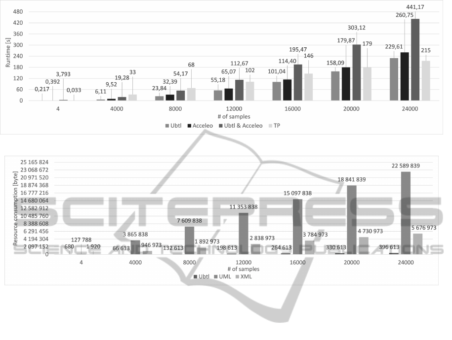
Figure 8: Runtime performance for different amount of test data (i.e., number of input and output values).
Figure 9: Resource consumption (file size) for different volumes of test data (i.e., number of input and output values).
REFERENCES
Arpaia, P., Buzio, M., Fiscarelli, L., Inglese, V., La Com-
mara, G., and Walckiers, L. (2009). Measurement-
Domain Specific Language for magnetic test specifi-
cations at CERN. In 2009 IEEE Intrumentation and
Measurement Technology Conference, pages 1716–
1720. IEEE.
Bagnato, A., Sadovykh, A., Brosse, E., and Vos, T. E.
(2013). The OMG UML Testing Profile in Use–An
Industrial Case Study for the Future Internet Testing.
In 2013 17th European Conference on Software Main-
tenance and Reengineering, pages 457–460. IEEE.
Baker, P., Dai, Z. R., Grabowski, J., Haugen, O. y., Schiefer-
decker, I., and Williams, C. (2008). Model-Driven
Testing: Using the UML Testing Profile. Springer
Berlin Heidelberg, Berlin, Heidelberg.
Bellard, F. (2014). Website of the QEMU Project.
http://www.qemu.org/.
BITCOM (2008). A study to relevance of embedded sys-
tems in germany. BITKOM Germany.
Debruyne, V., Simonot-Lion, F., and Trinquet, Y. (2005).
EAST-ADL An Architecture Description Language.
In Dissaux, P., Filali-Amine, M., Michel, P., and Ver-
nadat, F., editors, Architecture Description Languages
SE - 12, volume 176 of IFIP The International Fed-
eration for Information Processing, pages 181–195.
Springer US.
Ebert, C. and Jones, C. (2009). Embedded software: Facts,
figures, and future. Computer, 42(4):42–52.
Eclipse Foundation (2014a). MDT-UML2-Tool-
Compatibility. http://wiki.eclipse.org/MDT-UML2-
Tool-Compatibility.
Eclipse Foundation (2014b). Website of the Acceleo
Project. http://www.eclipse.org/acceleo/.
Eclipse Foundation (2014c). Website of the EMF Project.
http://www.eclipse.org/modeling/emf/.
Eclipse Foundation (2014d). Website of the UML2 Project.
http://www.eclipse.org/modeling/mdt/.
Eclipse Foundation (2014e). Website of the Xtend Project.
http://www.eclipse.org/xtend/.
Eclipse Foundation (2014f). Website of the Xtext Project.
http://www.eclipse.org/Xtext/.
ETSI (2014a). Methods for Testing and Specification
(MTS); The Test Description Language (TDL); Speci-
fication of the Abstract Syntax and Associated Seman-
tics Version 1.1.1.
ETSI (2014b). TTCN-3: TTCN-3 Runtime Interface Ver-
sion 4.6.1.
Feiler, P., Hansson, J., de Niz, D., and Wrage, L. (2009).
System architecture virtual integration: An indus-
trial case study. Software Engineering Institute,
Carnegie Mellon University, Pittsburgh, Pennsylva-
nia, CMU/SEI-2009-TR-017.
Fowler, M. (2010). Domain-Specific Languages. Addison-
Wesley Signature Series (Fowler). Pearson Education.
Ubtl-UMLTestingProfilebasedTestingLanguage
109

Gronback, R. C. (2009). Eclipse Modeling Project: A
Domain-Specific Language (DSL) Toolkit. Addison-
Wesley Professional, 1st edition.
Guduvan, A.-R., Waeselynck, H., Wiels, V., Durrieu, G.,
Fusero, Y., and Schieber, M. (2013). A Meta-Model
for Tests of Avionics Embedded Systems. In Proceed-
ings of the 1st International Conference on Model-
Driven Engineering and Software Development, pages
5–13. SciTePress.
Hernandez, Y., King, T. M., Pava, J., and Clarke, P. J.
(2008). A Meta-Model to Support Regression Test-
ing of Web Applications. In SEKE, pages 500–505.
Iyenghar, P., Pulvermueller, E., and Westerkamp, C. (2011).
Towards Model-Based Test automation for embedded
systems using UML and UTP. In ETFA2011, pages
1–9. IEEE.
John, K. H. and Tiegelkamp, M. (2010). IEC 61131-3: Pro-
gramming Industrial Automation Systems Concepts
and Programming Languages, Requirements for Pro-
gramming Systems, Decision-Making Aids. Springer
Publishing Company, Incorporated, 2nd edition.
Kumar, B. and Jasperneite, J. (2008). Industrial communi-
cation protocol engineering using UML 2.0: A case
study. In 2008 IEEE International Workshop on Fac-
tory Communication Systems, pages 247–250. IEEE.
Mews, M., Svacina, J., and Weiß leder, S. (2012). From
AUTOSAR Models to Co-simulation for MiL-Testing
in the Automotive Domain. In 2012 IEEE Fifth Inter-
national Conference on Software Testing, Verification
and Validation, pages 519–528. IEEE.
Object Management Group (OMG) (2008). MOF Model to
Text Transformation Language Version 1.0.
Object Management Group (OMG) (2013). UML Testing
Profile (UTP) Version 1.2.
Object Management Group (OMG) (2014). Website of the
Unified Modeling Language. http://uml.org/.
Schieferdecker, I. and Din, G. (2004). A Meta-model for
TTCN-3. In N´u˜nez, M., Maamar, Z., Pelayo, F.,
Pousttchi, K., and Rubio, F., editors, Applying Formal
Methods: Testing, Performance, and M/E-Commerce
SE - 27, volume 3236 of Lecture Notes in Computer
Science, pages 366–379. Springer Berlin Heidelberg.
Smith, D. and Simpson, K. (2010). A Straightforward
Guide to Functional Safety, IEC 61508 (2010 Edition)
and Related Standards, Including Process IEC 61511
and Machinery IEC 62061 and ISO 13849. Elsevier
Science.
Ulrich, A., Jell, S., Votintseva, A., and Kull, A. (2014).
The ETSI Test Description Language TDL and its Ap-
plication. In Pires, L. F., Hammoudi, S., Filipe, J.,
and das Neves, R. C., editors, MODELSWARD, pages
601–608. SciTePress.
MODELSWARD2015-3rdInternationalConferenceonModel-DrivenEngineeringandSoftwareDevelopment
110
