
Using a Token Approach for the MAC Layer of Linear Sensor Networks
Impact of the Redundancy on the Throughput
El Hadji Malick Ndoye
1,2
, Fr´ed´erique Jacquet
1
, Michel Misson
1
and Ibrahima Niang
2
1
Clermont Universit´e / LIMOS CNRS - Complexe Scientifique des C´ezeaux, 63172 Aubi`ere cedex, France
2
Laboratoire d’Informatique, Universit´e Cheikh Anta Diop de Dakar (UCAD), B.P. 5005 Dakar-Fann, S´en´egal
Keywords:
Wireless Sensor Network, Linear Topology, Throughput, Mac Protocol, Token Passing.
Abstract:
Wireless Sensor Networks (WSNs) consist of a large number of sensor nodes deployed in a wide area for
monitoring applications. For some of these applications, as pipeline or road monitoring, wireless sensor nodes
have to be deployed in a linear manner. We refer to these WSNs as Linear Sensor Networks (LSNs). Due to
specificity of LSNs, MAC protocol designed for WSNs, as contention or TDMA based protocols, are often
not suitable. Furthermore, wireless node deployment can provide a certain form of redundancy to prevent
link or node failures. In this paper, we propose a token based MAC protocol for linear sensor networks in
order to improve the network performance. We evaluate the effect of the redundancy on the number of packets
delivered to the sink. We show that the redundancy induces a significant improvement both on the delivered
traffic and on the FIFO queue size of the nodes.
1 INTRODUCTION
Wireless sensor networks (WSNs) are used to observe
and react to eventsand phenomena in order to perform
environmental monitoring. Very often, the geometry
of the WSN is linear du to the monitored objects. A
such geometry can be found in applications like de-
tection of the presence of workers in a gallery of an
underground mine (Li and Liu, 2009) or fluid leaks in
water or oil pipelines (Jawhar et al., 2007)(Ted et al.,
2012)(SunHee et al., 2009), in transmission of data
between the wagons of a freight train (Zimmerling
et al., 2008)(Wang et al., 2011)(Berlin and Van Laer-
hovenand, 2013), in the monitoring of roads, bridges
and tunnels (Meng et al., 2008). In this paper, we refer
to these networks as Linear Sensor Networks (LSNs).
We focus on an application where packets have to
reach a sink station arbitrarily located at the right end
of the network. In LSNs each node has some neigh-
bors to its left (they are called left neighbors) and to
its right (they are called right neighbors). When sen-
sor nodes are aligned on a straight line strictly form-
ing a line, or a thin LSN as defined in (Jawhar et al.,
2008), the network has to deal with two identified
drawbacks: the link or node failure impacting the con-
nectivity and the hidden terminal problem impacting
the frame loss rate. This is why we are considering
both the use of a token passing mechanism and the
use of a light redundancy for LSN topology, provid-
ing alternative paths for the traffic. We assume a uni-
form placement of nodes, where the Sink is located at
one end and a first node named Allocator at the other
end. The allocator is in charge of providing tokens
periodically.
Enhancing throughput and robustness, is one of
the most important challenge in LSN. The density of
the topology (number of neighbors of a current node)
is low and depending on the propagation conditions
and on the stability of the wireless links. This density
will be used to introduce the redundancy of a LSN
topology. If each node has only two neighbors, ie one
on its right and one its left, the LSN is strictly lin-
ear. We called it 1-Redundancy LSN topology. When
each node has 2*R neighbors, both R on its right and
on its left, we are dealing with a R-Redundancy LSN
topology allowing routing facilities. In this paper, we
evaluate the impact of R on the traffic reaching the
sink. The LSN topologies expose packets to the ef-
fect of the hidden problem and induce high latency
(Noori and Arkani, 2008). So, the need of a suitable
MAC protocol for network performance improvement
is a real challenge in LSN. We propose a token based
MAC protocol for LSNs deployed according a R-
Redundancy topology (R varying from 1 to 3). The
authorization to transmit is granted via the reception
of a token ie a specific short frame. Tokens are pro-
122
Ndoye E., Jacquet F., Misson M. and Niang I..
Using a Token Approach for the MAC Layer of Linear Sensor Networks - Impact of the Redundancy on the Throughput.
DOI: 10.5220/0005243501220129
In Proceedings of the 4th International Conference on Sensor Networks (SENSORNETS-2015), pages 122-129
ISBN: 978-989-758-086-4
Copyright
c
2015 SCITEPRESS (Science and Technology Publications, Lda.)

vided periodically by the first node named Allocator
and then propagated from node to node. When a node
is token holder it is allowed to transmit uplink traf-
fic toward the sink and/or downlink traffic toward the
Allocator. Packets are sent to the targeted node in a
multi-hop manner following a path depending on the
redundancy factor R.
This paper is organized as follows: Section 2 jus-
tifies the choice of our MAC protocol and presents
the state of art on MAC protocol based on token
for wireless sensor networks for throughput improve-
ment. Section 3 introduces how the density allows us
to define a R-Redundancy LSN and for each value of
R, how to define the minimal distance between two
consecutive tokens. Section 4 presents details about
our token based MAC protocol. We show the mecha-
nism allowing a token holder node to transmit traffic
both toward the sink and toward the Allocator. Sec-
tion 5 evaluates theoretically the impact of the redun-
dancy on the optimum number of packets delivered to
the sink. Section 6 confirms the impact of factor R on
the optimal delivery rate, via NS2 simulation results.
Section 7 discuss about the theoretical and simulation
results obtained. This paper is concluded in Section
Section 8.
2 STATE OF ART
The usual MAC protocol based on contention or
TDMA are not suitable for LSNs. In the case of
contention MAC protocols such as protocols based
on Carrier Sense Multiple Access (CSMA) with or
without RTS/CTS (Ndoye et al., 2013), 802.15.4
CSMA, SMAC, TMAC, encounter collision problems
and induce congestion areas due to the hidden termi-
nal problem. Thus, packet retransmissions decrease
throughput at the sink. In the case of MAC proto-
cols based on slotted access method, such as protocols
based on Time Division Multiple Access (TDMA),
TRAMA, FLAMA, they require a strict synchroniza-
tion and/or a complex scheduling between nodes to
avoid large unproductive time guard intervals. The
drift of the clocks of the nodes decreases highly the
throughput due to the loss of packets and induces en-
ergy wasting.
In the research literature related to the specifici-
ties of linear wireless sensor networks, LSNs are of-
ten used to drain data from a set of nodes (raw con-
vergecast) in order to aggregate it in a sink. It is well
known that a hop by hop routing of data packets to
one or several specific sink nodes induces a kind of
concentration of traffic along the path followed by the
forwarded frames. At each hop along the path con-
ducting to a sink, an additional local traffic is gath-
ered to the data to be forwarded. This concentration
of traffic increases progressively along this path and
it may cause locally an overload of the medium. In
(Noori and Arkani, 2008) authors show that the traffic
increases progressivelywhen it gets closer to the sink.
Such areas are called congestion areas to point out the
fact that the MAC has to deal with a local load exceed-
ing the usual capacity of the medium. This causes
several drawbacks:
• An overload of the FIFO of node within the con-
gestion areas, inducing delays in the forwarding
process and a risk of frame dropping due to FIFO
overflow,
• An increasing of busy medium status returned by
channel sensing (CCA operation),
• An increasing rate of collisions increased by the
hidden terminal problem.
These two last phenomena cause losses of frames
(collision or dropping). In the literature, this spe-
cific behavior has been identified early for solutions
based on linear deployment of a wireless infrastruc-
ture made of 802.11 Access Points (Moutairou et al.,
2009). For WSN applications, many research focus
on the propriety of MAC protocol in order to avoid
congestion and thus improve the throughput. In re-
cent years, a lot of research focuses on token based
protocols due to the limitation of classic MAC proto-
cols (contention and TDMA). Nevertheless, most of
these proposed protocols do not match in linear sen-
sor network. ToKeN-TWiNs (TKN-TWN) described
in (Liu et al., 2013a) is a high throughput data col-
lection exploiting the advantages of TDMA. It eases
the scheduling burden by using two tokens to arbi-
trate transmission activities. Access to the medium
is organized by a centralized token passing mecha-
nism. The sink node generates two types of tokens
which are passed to two different top-subtrees, and a
multi-channel approach is used to avoid interference.
In (Liu et al., 2013b) an implementation and evalua-
tion of TKN-TWN in term of throughput is presented.
Authors show that in a binary-tree-formed network
ToKeN-TWiNs throughput outperforms the through-
put of collection protocol (Incel et al., 2012). This
proposition was designed for WSNs deployed accord-
ing to a tree topology and it loses a part of its in-
terest for linear topology. In (Fan et al., 2012) au-
thors present an Enhanced Dynamic Token Protocol
(EDTP) using TPQ as described in WDTP (Xianpu
et al., 2007). They show that in underwater acoustic
WSN, EDTP performs better throughputthan TDMA.
In (Na et al., 2009) authors describe a Data Filtration-
Aware MAC protocol for wireless Sensor Networks
UsingaTokenApproachfortheMACLayerofLinearSensorNetworks-ImpactoftheRedundancyontheThroughput
123

(DF-MAC). It is a token-based MAC protocol based
on TR-MAC (Na et al., 2007). Indeed, after nodes se-
lection and the formation of a logical ring, data trans-
mission is performed by using a token. It was shown
that DF-MAC provides a better throughput than TR-
MAC. Unfortunately, DF-MAC is designed for clus-
tered network and cannot be relevant for LSNs. Even
if the token based protocols presented above improve
performance of classic or clustered WSNs, they are
not designed for LSNs and they do not take advantage
of the specificities of such a topology. The design of a
MAC protocol for a LSN must consider a trade-offbe-
tween the specificities of this kind of networks: topol-
ogy, low density, small processing power, energy lim-
itations, etc. We propose a MAC protocol based on a
slotted access method needing a soft synchronization
and taking advantage of linearity of the deployment
of nodes. The use of a token to propagate the right
to transmit is a way to avoid the constraints of a strict
and global synchronization.
Before sending data frames, a current node has to
wait the reception of a token from one of its neigh-
bors. When this token reception occurs, this current
node becomes Token Holder for a given amount of
time SD (Shuttle Duration). Then this node can trans-
mit uplink traffic toward the sink or downlink traffic
toward the Allocator, details will be given in the next
paragraph. The token frame contains information as
the token generationperiod, the sleep and wakeup cal-
endar. We evaluate our protocol in terms of through-
put in order to show the impact of redundancy of lin-
ear network sensor on its behavior.
3 HYPOTHESES AND NETWORK
TOPOLOGY
We outline now the details about the density of LSNs
we are studying, the timing of MAC protocol we pro-
pose and the traffic model we use in this paper. In
the following, we consider a one-dimensional LSN of
N nodes uniformly placed over a length-L with equal
distance d between two adjacent nodes. The kind of
LSN we are going to use is depending on the density
of the topology. If the radio range p and the distance
d between nodes are such that d < p < 2d, each node
has two neighbors (one to its left and one to its right).
We are dealing with a strictly LSN having a density
of 2 as shown in Fig. 1a. As defined previously it is a
1-Redundant LSN.
When p > 2d, each node has at least 4 neighbors
(two or more to its left and two or more to its right).
For such topology, if a link is broken or a node is
out of order it is still possible to forward the frames
(mainly to the sink) by skipping the defective device.
This kind of LSN is called R-redundant where R is the
number of neighbors in each direction (right and left).
A 2-redundant as shown in Fig. 1b. In the following,
we focus on this kind of redundantLSNs, and we refer
to them as 2-Redundant LSNs or 3-Redundant LSNs
according to their density.
Fig. 1b: Nodes of a 2−Redundant LSN
Fig. 1a: Nodes of a strictly LSN
Figure 1: LSN topologies.
Each node has its own ID. In this paper we sup-
pose the following points: (i) the node located at left
end of the LSN is Node 1 and is the Allocator provid-
ing tokens, (ii) the node at the right side of Node I is
Node I+1, (iii) the node located at the right end of the
LSN is the Sink. The routing (or forwarding) scheme
works as follows. Each node transmits data frames to
its one-hop or R-hop neighbor according to the LSN
topology.
In our simulation, the model we use for a current
node is given in Fig. 2. A queue for packets is at-
tached to each node; this queue is connected to the
next node. In the following, we show the impact of
the FIFO size and of the Shuttle Duration length on
the number of packets delivered to the sink. Pack-
ets flow from the left to the right and a local load is
injected into the queue of each node. For many rea-
sons such as (i) retransmission credit exceeded (oc-
curs when a node has transmitted five times the same
data frame without receiving any acknowledgment),
(ii) queue overload (occurs when the queue of the
node is requested to keep too many packets), packets
may not be received by the sink. We define the ag-
gregate throughput as the number of packets received
by the sink per unit of time. Throughput increases as
the offered load provided by nodes (packets locally
produced) increases. When the offered load reaches
a certain threshold, the throughput does not increase
any more. Sometimes, it can even start to decrease.
We denote by t a period of time including several to-
ken periods, we can define the aggregate throughput
of the LSN as:
S =
n∗PacketsLength
t
where n is the number of pack-
ets received by the sink during t. This throughput will
be used for the evaluation of the efficiency of the To-
ken MAC protocol according to the redundancy of the
LSN.
SENSORNETS2015-4thInternationalConferenceonSensorNetworks
124

MAC
address
filter
MAC
Mechanism
Physical layer
(Traffic generator)
Local application
Next node
Current node
local FIFO
Previous node
Uplink traffic Downlink traffic
Forwared traffic
Figure 2: Node Model.
4 OUR PROPOSAL: TOKEN
BASED MAC PROTOCOL
In this section we describe our proposal token based
MAC protocol for LSNs.
4.1 Access Control
The token generation governing the access to the
medium is initiated by the Allocator. It produces
a token which circulates from node to node until it
reaches the sink. In the following, the path followed
by a token is always A, B, C, , Sink. Each node which
receives a token is allowed to transmit during a given
time called shuttle duration. So, a node has two major
states: it is either token holder, or waiting for a token.
In token holder state, the node can transmit differently
data frames during the shuttle duration, according to
three consecutive periods. (i) T
1
: during this amount
of time the node transmit data frames to its neighbor
toward the Allocator. This traffic is called downlink
traffic and comes from the sink. (ii) T
2
: during this
amount of time the node transmit data to the sink.
This traffic is called uplink traffic. (iii) At the begin-
ning of period T
2
, the node being token holder passes
the token to its neighbor at its right side and reaches
the waiting for a token state. When there is no pend-
ing downlink traffic, a token holder node uses also T
1
for uplink traffic. When a node is in the waiting token
state, it can either listen for uplink or for downlink
packets coming from the sink, it can also switch off
its radio to save energy. The temporal pattern of the
activity of a current node is given on Fig. 3.
4.2 Periodicity of the Token Production
In this section, we define the minimal distance in term
of nodes between two consecutive tokens in order to
have several tokens circulating in the network at the
same time. This distance must be calculated accord-
ing to the transmission range of each node and on the
downlink traffic
Listening for
receptionuplink traffic uplink traffic
Transmitting ofTransmitting ofTransmitting ofThe token Listening for
downlink trafficthe token
Shuttle
T
0
T’
0
T
1
T
2
T
2
’
T
3
Shuttle Duration (ShuDur)
Figure 3: Example of token passing.
possibility of having downlink traffic. In Fig. 4a, it
is shown that in a strictly LSN with downlink traffic,
the distance between two token holders is three nodes
(four hops). The part of the LSN corresponding to
nodes (A, B, C and D) as shown in can be consid-
ered as a cluster moving from node to node at each
expiration of the shuttle duration. So, in the case of
strictly LSN the size of the cluster (CluSize) is set to
four hops. So if a reverse traffic is possible, a node is
token holder at most only a quarter of its time. Dur-
ing three quarters of its time, it has to queue the traffic
locally produced.
During the remaining quarter of its time, the node has
to queue (in an interleaved manner) the local traffic in
addition to the traffic forwarded by the previous node
of the LSN. If the radio range allows the possibility to
exchange with its two-hop neighbors, the spatial reuse
becomes less efficient, as it requires an increase in the
distance between two nodes being simultaneously in
the token holding state.
As shown in Fig. 4b, for a 2-redundant LSN, two
token holder nodes have to be separated by at least
four nodes when the traffic is only for the sink, and
by six nodes when a reverse traffic is possible. The
size of the linear cluster (CluSize) is respectively 5
and 7. The minimal distance between two successive
token holder nodes has a strong impact on the network
performance and on the token production activity of
the allocator. For a given token holding time ( T
1
+
T
2
+ T’
2
as defined in Fig. 3), the minimal period of
token production is given T
Token
(min) = ShuDur x
CluSize.
The time separating two consecutivetokens T
Token
must be greater than T
Token
(min); the choice of this
period has to be done by considering the following
factors: the energy autonomy of nodes, the profile of
the offered traffic load, and so on.
UsingaTokenApproachfortheMACLayerofLinearSensorNetworks-ImpactoftheRedundancyontheThroughput
125

A B
C D
E
GF
H
X
A B
C ED
Ack
Uplink Traffic
Fig. 4a: Distance between token holders for a strictly LSN
Uplink Traffic A−>C
Ack F−>H
Downlink Traffic H−>FAck C−>A
Fig. 4b: Distance between token holders for a 2−Redundant LSN
Token holder node
Downlink Traffic
Figure 4: Distance between token holders.
5 MECHANISM OF TOKEN
REDUNDANCY
The creation and the forwarding of a new token by
the Allocator, allows the traffic of the nodes to be
drained in a multi-hop manner. Each time a node
is token holder, it can transmit (i) first the traffic to-
wards the Allocator (downlink traffic), (ii) and during
the remaining holding time, the traffic having the sink
as destination (uplink traffic). Our choice to allow
uplink and downlink traffic has an impact on the fre-
quency of the token production. The distance between
two consecutive nodes being token holder, expressed
in number of hops, depends on the range of the ra-
dio link and on the distance between two consecutive
nodes.
We can notice that the case of a strictly linear net-
work, it is easy to show (Fig. 4) that the distance be-
tween two nodes being token holder is equal to four
hops. That is to say 3 times the radio range expressed
in number of hops plus 1. For a 2-redundant LSN,
this distance increases to 7 hops (3 times the radio
range plus 1) and for a 3-redundant LSN this distance
reaches 10 hops (3 times the range plus 1).
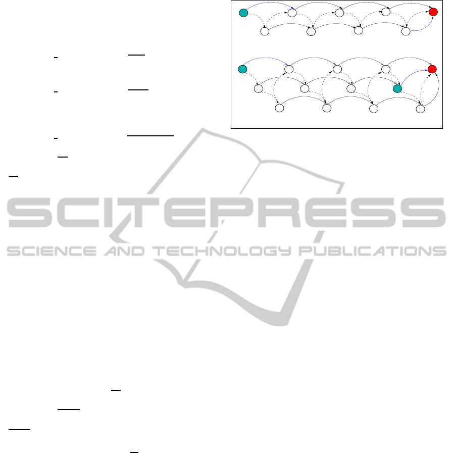
Fig. 5.a and Fig. 5.b are used to introduce how
the token passing is managed and how the path of
data packets takes advantage of redundancy.In the-
sefigures, dashed arrows indicate the path systemat-
ically followed by the tokens: A −→ B −→ C ... −→
Sink, blue arrows indicate the links which are simul-
taneously active at a given point in time. Fig. 5.a is for
the 2-Redundant case, the traffic generated by node A
is transmitted directly to node C to be concatenated
with the traffic locally generated. This traffic is then
forwarded to node E and so on. In such a network it
can be seen that there is two branches (A, C, E, G)
and (B, D, F,H) which converge towards the sink.
Fig. 5.b is for the 3-redundant case. The traffic
generated by node A is transmitted directly to node
D to be concatenated with the traffic locally gener-
ated. This traffic is then transmitted to node G and
so on. In such a network, three branches converging
towards the sink S, can be identified :(A, D, G, J),
(B, E, H, K) and (C, F, I, L).This way of spreading
the LSN traffic over these three branches has an im-
pact on performance in terms of throughput. Let us
consider Fig. 5.b when node A and node K are token
holder, Node A is allowed to transmit data packets to
D, and then its token to B, Node K will directly trans-
mit its data packets to the sink and its token to L.We
can notice two important things:
• The sink can receive data packets every time one
of its neighbors is token holder. So for a 3-
Redundant LSN, the same token gives 3 oppor-
tunities to the sink to receive data packets. Each
token allows the sink S of Fig. 5.b to receive con-
secutively from J, K and L.
• The FIFO of each node being a neighbor of the
sink must be large enough to store and forward the
traffic of its branch. So for a 3-Redundant LSN,
the evaluation of the FIFO size of a sink neighbor
node is only governed by the traffic of its branch.
The FIFO size of node K of Fig. 5.b is supposed
to be larger enough to concatenate the traffic of
nodes of the branch (A, D, G, J).
The two previous points will be used to evaluate the
throughput capacity of a LSN according to the redun-
dancy factor R. For R equals from 1 to 3, we want to
estimate the optimal number of packets delivered to
the sink for a given bit rate.
The word optimal is used here to point out the fact
the FIFO size is adjusted to the shuttle duration to
maximize the throughput and to avoid the loss of data
packets. For this evaluation we chose to deal with
medium sized data packets and we suppose that all the
nodes of the same FIFO size for generality purpose.
Each neighbor of the sink is token holder during just
enough time to empty its FIFO. A direct consequence
of this hypothesis is that the size of the FIFO equals
the maximum number of data packets a token holder
can sent before passing the token. In others words,
the capacity of the shuttle is equal to the size of the
node FIFO.
Let SC (Shuttle Capacity) be the number of pack-
ets a shuttle can carry. For a 1-Redundant LSN, the
sink receives P packets by token, ie P packets for each
time period of 4 ShuttleDurations(SD). The delivery
rate of data packets to the sink is
Theoretical
Throughput(1)=
1∗SC
4∗SD
expressed in
packets per second
For a 2-redundant network and for each token, the
sink receives S packets from its one hop neighbor but
SENSORNETS2015-4thInternationalConferenceonSensorNetworks
126
also S packets from its two hop neighbor. For such a
case two consecutive tokens are separated by 7 Shut-
tle Durations. The delivery rate of data packets to the
sink is
Theoretical
Throughput(2) =
2∗SC
7∗SD
For the case of Fig. 5.b, this delivery rate becomes
Theoretical
Throughput(3) =
3∗SC
10∗SD
For an R-redundant LSN, this can be generalized
by:
Theoretical
Throughput(R) =
R∗SC
((3∗R+1)∗SD)
Concerning
SC
SD
:
SC
SD
is common ratio independent of R, but depend-
ing on the value of parameters of physical and MAC
layer used for the LSN. The implementation follow-
ing this study will be based on the physical layer of
802.15.4, it is why this evaluation will be done us-
ing a bit rate of 250 Kbps. The throughput evaluation
is based on 100 byte data-frames; the length of the
data-frames has not a significant impact on through-
put. The use of short frames reduces slightly the
throughputintroducing more overheadbut it improves
the end-to-end delay.
Simulations allow estimating the average time be-
tween the transmissions of two consecutive acknowl-
edged frames. This time is useful to estimate the ca-
pacity of the shuttle that is to say the number of pack-
ets a node is able to send while being token holder.
If each node is token holder during 250 ms (SD) and
if transmitting period is 4.5 ms, the shuttle capacity
(SC) is about 55 packets. So
SC
SD
is equal to 44 kbps
Concerning
R
3∗R+1
R
3∗R+1
is an increasing function. It starts at 0.25
and converges to 0.33. The optimum throughput ob-
tained for a 3-redundant LSN is
12
10
higher than that
of a strictly linear network, so this function can be
considered as a redundancy gain. This throughput in-
crease has no impact on the FIFO size of the nodes.
Traffic of a branch of such a network should be cal-
culated so that the node of this branch that is neigh-
bor of the sink contains at most SC packets when it
becomes token holder. In this theoretical evaluation
of the impact of factor R on the delivery packet ra-
tio, the time needed for the token passing mechanism
was neglected. This choice has no real impact if each
node remains token holder in order to send a signif-
icant number of data frames. In the following is on
this theoretical approach that simulations have been
carried out. Simulation results confirm the expected
gain in term of throughput.
D
A
C
E
F
H
E
F
G
H
I
K
L
Fig 5.a: Clusters formation in a 2−Redundant LSN
Fig 5.b: Clusters formation in a 3−Redundant LSN
B
D
A
C
G
B
J
S
S
Figure 5: Clusters formation in LSNs.
6 EVALUATION
We perform our simulations on NS2 (version 2.32).
Our results are given for a linear network of sixteen
nodes: node 1 (the Allocator), is on the left side, and
node 16 (the Sink), is on the right side. Local traffic
is produced pseudo-periodically and starts randomly
between 0 and 1 second, and independently for each
node. A given current node might receive traffic to be
forwarded when one of its neighbors becomes token
holder. We suppose in the following that all the nodes
of the LSN have the same type of queue managed in
a first in first out (FIFO) manner. The capacity of this
queue can be expressed by the number of packets (Fi-
FoSize) it can contain. The existence of a channel for
a downlink traffic is an interesting capability allowing
the possibility of changing the period of token gener-
ation for example, but, in the following we suppose
that the number of packets targeted to the sink repre-
sents the dominant traffic. The size of the reverse traf-
fic is ignored in our simulations. The capture model is
defined as in 802.15.4 and the new reception capture
threshold is set to 10 dBm. The propagation model is
Tworayground and we suppose also that all the pack-
ets have the same size. In this paper, we focus on the
throughput as described above.
Table 1 presents the simulation parameters.
Fig. 6, Fig. 7 and Fig. 8 present the performances
parameters in a 1-Redundant, 2-Redundant and 3-
Redundant LSN in term of throughput in order to
show the impact of the redundancy. They evaluate
the evolution of the throughput as a function of data
transmission rate for a given shuttle duration. For
each shuttle duration, two phases can be identified:
between 8 and 48 Kbps the throughput evolution in-
creases. Indeed, in this phase, the load of the network
is low and thus FIFO contain a few number of data
packets for uplink traffic. The number of packets re-
ceived by the sink from its direct neighbors per sec-
ond is low. In this phase, nodes do not transmit any
UsingaTokenApproachfortheMACLayerofLinearSensorNetworks-ImpactoftheRedundancyontheThroughput
127
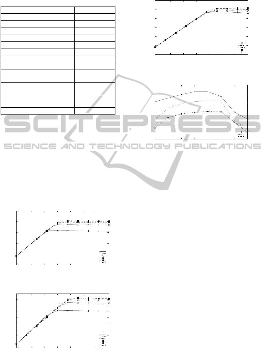
Table 1: Simulation parameters.
Parameter Value
Downlink traffic time 10 ms
Shuttle duration [50-300]ms
Token packet size 11 bytes
Data packet size 100 bytes
Number of repetitions 50
Physical Layer 802.15.4
Transmission Power -5 dBm
FiFoSize 60
Distance between two nodes in 1-
Redundant LSN
90 meters
Distance between two nodes in 2-
Redundant LSN
45 meters
Distance between two nodes in 3-
Redundant LSN
30 meters
Data transmission rate [8-80] Kbps
uplink traffic most of the shuttle duration. Between
48 and 80 Kbps the throughput evolution is station-
ary. During this phase the load of the network induces
saturation. The FIFOs contain the maximal number
of packets that can be sent during the shuttle duration.
So, the number of packet received by the sink from its
direct neighbor is constant. During this phase, nodes
send uplink traffic most of the shuttle duration.
The impact of the redundancy can be shown also
in Fig. 6, Fig. 7 and Fig. 8. Indeed, the throughput
at the sink for each shuttle duration and for a given
data transmission rate is higher for the 3-Redundant
Shuttle duration = 50 ms
Shuttle duration = 100 ms
Shuttle duration = 150 ms
Shuttle duration = 200 ms
Shuttle duration = 250 ms
Shuttle duration = 300 ms
0
10
20
30
40
50
10 20 30 40 50 60 70 80
Throughput (Kbps)
Data Transmission Rate (Kbps)
Figure 6: Throughput comparison by Shuttle duration in a
1-Redundant LSN.
Shuttle duration = 50 ms
Shuttle duration = 100 ms
Shuttle duration = 150 ms
Shuttle duration = 200 ms
Shuttle duration = 250 ms
Shuttle duration = 300 ms
5
10
15
20
25
30
35
40
45
50
10 20 30 40 50 60 70 80
Throughput (Kbps)
Data Transmission Rate (Kbps)
Figure 7: Throughput comparison by Shuttle duration in a
2-Redundant LSN.
Shuttle duration = 50 ms
Shuttle duration = 100 ms
Shuttle duration = 150 ms
Shuttle duration = 200 ms
Shuttle duration = 250 ms
Shuttle duration = 300 ms
0
10
20
30
40
50
60
10 20 30 40 50 60 70 80
Throughput (Kbps)
Data transmission Rate (Kbps)
Figure 8: Throughput comparison by Shuttle duration in a
3-Redundant LSN.
3−Redundant LSN
2−Redundant LSN
1−Redundant LSN
25
30
35
40
45
50
55
50 100 150 200 250 300 350 400
Maximal Throughput (Kbps)
Shuttle duration (ms)
Figure 9: Maximal throughput for data transmission rate of
80 Kbps for various shuttle duration. The maximal through-
put is achieved with a shuttle duration of 250 ms.
LSN and followed by the 2-Redundant LSN. For ex-
ample for a shuttle = 50 ms, data transmission rate
= 80 Kbps we have for3-Redundant: 45.5 Kbps, for
2-Redundand: 35.5 Kbp and for 1-Redundant: 31.1
Kbps. This confirms our theoretical analysis. Fig. 9
shows the maximal throughput for a data transmis-
sion rate of 80 Kbps for various values of the shuttle
duration. This figure shows that maximal throughput
is obtained for a shuttle duration of 250 ms. Indeed,
direct neighbors from the sink transmit maximal num-
ber of packets from thier FIFO. Also, they are in the
most time of the shuttle in transmitting state. Con-
trarily for the shuttle duration of 300 where nodes are
more often in waiting state due to the fact that the
FIFO are empty before the end of the shuttle. That is
why the throughput decreases for a shuttle of 400 ms.
The impact of the redundancy can be shown. The
maximal throughput is for the 3-Redundant LSN (
traffic from 3 direct neighbors of the sink) is 51.27
Kbps , 46.13 Kbps for the 2-Redundant LSN and
40.37 Kbps for the 1-Redundant LSN.
7 DISCUSSION
The maximal throughput given by simulation is al-
ways slightly lower than the theoretical throughput.
Some frames must be repeated on the path followed
SENSORNETS2015-4thInternationalConferenceonSensorNetworks
128

Table 2: Throughput comparison between theoretical and
simulation analysis.
R Theoretical
Throughput (Kbps)
Throughput from
simulation (Kbps)
1 44 40.37
2 50.3 46.13
3 53 51.27
to reach the sink. This is decided after the expiration
of the timer used to detect a no-acknowledgement. It
is the main reason of this slight difference. Table 2
presents the comparison between theoretical and sim-
ulations results.
8 CONCLUSION
Linear Sensor Networks (LSNs) have a large interest
for monitoring applications. In this paper , we pro-
pose a token based MAC protocol to manage the ac-
cess to the medium. We study the behavior of LSN
in the case of three topologies. Thus, we define a R-
redundant LSN where R is the number of neighbors
in each direction for a given node. Specifically, we
study the impact of the redundancy on the throughput
at the sink. We show that by theoretical and simu-
lation analysis that more the factor of redundancy R
is great more the throughput at the sink is also great.
We show also that the redundant allows nodes to have
an equitable distribution of the traffic by dividing the
network into branches.
In future works, we plane to reverse channel in
order to master the token production frequency ac-
cording to the spatial reuse and energy saving con-
straints. Another way to improve the capacity of such
a network is to add a priority policy to the node FIFO
management by allowing highest priorities to the data
frames coming from the farthest nodes. Finally, we
plane to use a Log-normal Shadowing model in order
to model the path loss due to the environment fluctu-
ations.
REFERENCES
Berlin, E. and Van Laerhovenand, K. (2013). Sensor net-
works for railway monitoring: Detecting trains from
their distributed vibration footprints. In IEEE Interna-
tional Conference on Distributed Computing in Sen-
sor Systems.
Fan, G., Li, J., Liu, W., and Zhao, Y. (2012). An enhanced
dynamic token protocol for underwater accoustic sen-
sor networks. In International journal on smart sens-
ing and intelligent systems, volume 4.
Incel, O. D., Ghosh, A., Krishnamachari, B., and Chinta-
lapudi, K. (2012). Fast data collection in tree-based
wireless sensor networks. In IEEE Transactions on
Mobile Computing, volume 11, pages 86–99.
Jawhar, I., Mohamed, N., Shuaib, K., and Kesserwan, N.
(2008). An efficient framework and networking pro-
tocol for linear wireless sensor networks. Ad Hoc &
Sensor Wireless Networks, 7(1-2):1–9.
Jawhar, I., Nader, M., and Shuaib, K. (2007). A framework
for pipeline infrastructure monitoring using wire-
less sensor networks. In The Sixth Annual Wire-
less Telecommunications Symposium (WTS 2007),
Pomona, California, USA.
Li, M. and Liu, Y. (2009). Underground coal mine monitor-
ing with wireless sensor networks. ACM Trans. Sen.
Netw., 5(2):10:1–10:29.
Liu, J., Suzuki, M., Lee, D. ., and morikawa, H. (2013a). A
token scheduled high throughput multi-channel data
collection protocol for wireless sensor network. In
Proc. IEEE Veh. Technol. Conf.
Liu, J., Suzuki, M., Lee, D., and morikawa, H. (2013b). Im-
plementation and evaluation of token-scheduled col-
lection protocol in wireless sensor network. In Proc.
IEEE Veh. Technol. Conf.
Meng, S., Kunqing, X., Xiujun, M., and Guojie, S. (2008).
An on-road wireless sensor network approach for ur-
ban traffic state monitoring. In IEEE Conference on
Intelligent Transportation Systems.
Moutairou, M. M., Aniss, H., Delisle, G. Y., and Hakem,
N. (2009). Global optimization of multi radio mesh
access point location in underground area. Journal of
Networks, 4(7):630–640.
Na, L., Yuanan, L., Bihua, T., and Fan, W. (2009). A data
filtration-aware mac protocol for wireless sensor net-
works. In IEEE Transactions on Mobile Computing.
Na, L., Yuanan, L., Bihua, T., Fan, W., Lidong, Z., and
Gang, X. (2007). A new mac protocol based on to-
ken ring in wireless sensor networks. In Interna-
tional Symposium on Communications and Informa-
tion Technologies.
Ndoye, E. H. M., Jacquet, F., Misson, M., and Niang, I.
(2013). Evaluation of rts/cts with unslotted csma/ca
algorithm in linear sensor networks. In NICST 2013.
Noori, M. and Arkani, M. (2008). Characterizing the traffic
distribution in linear wireless sensor networks. IEEE
Communications Letters, 12:554–556.
SunHee, Y., Wei, Y., Jhon, H., Brian, L., and Cyrus, S.
(2009). Swats: Wireless sensor networks for steam-
flood and waterflood pipeline monitoring.
Ted, T.-T. L., Kuei-Han, L., Polly, H., and Hao-Hua, C.
(2012). Triopusnet: Automating wireless sensor net-
work deployment and replacement in pipeline moni-
toring. In IPSN’12, Beijing, China.
Wang, N., Meng, Q., Li, T., and Ma, Q. (2011). Research on
linear wireless sensor networks used for on-line mon-
itoring of rolling bearing in freight train. In 9th Inter-
national Conference on Damage Assessment of Struc-
tures.
Xianpu, S., Yanling, Z., and Jiandong, L. (2007). Wireless
dynamic token protocol for manet. In International
Conference on Parallel Processing Workshops.
Zimmerling, M., Dargie, W., and M. Reason, J. (2008). Lo-
calized power-aware routing in linear wireless sensor
networks. In The 2nd ACM Workshop on Context-
Awareness for Self-managing Systems, Sydney, Aus-
tralia.
UsingaTokenApproachfortheMACLayerofLinearSensorNetworks-ImpactoftheRedundancyontheThroughput
129
