
New Solutions for Optimal Hardware Tests of Reconfigurable Hardware
Systems
Asma Ben Ahmed
1,2
, Olfa Mosbahi
1
and Mohamed Khalgui
1
1
LISI Laboratory, National Institute of Applied Sciences and Technology , University of Carthage, Carthage, Tunisia
2
Tunisia Polytechnic School, University of Carthage, Carthage, Tunisia
Keywords:
Embedded System, Reconfiguration, Hardware Verification, Testing, Fault Collapsing, Optimization.
Abstract:
This research paper deals with Reconfigurable Hardware Systems (abbreviated, RHS) that should be adapted to
their environment under well-defined conditions. A reconfiguration scenario is a run-time hardware operation
allowing the addition/removal of hardware components. We classify the reconfiguration scenarios into three
levels: Architectural, Structural and Data Reconfiguration Levels. We propose a new solution for optimal
hardware tests of RHS based on the definition of new fault collapsing relationships termed Inter-Equivalence,
Inter-Dominance and Redundancy.
1 INTRODUCTION
In recent years, embedded systems have become ubiq-
uitous at a fast rate. An embedded system is a com-
puting machine designed for specific functions within
a larger system. Embedded systems often require
stringent performance, energy efficiency and flexi-
bility for multifunctional use. In order to cope ef-
fectively and timely with these requirements, recon-
figuration of system components at different levels
of abstraction has become a crucial task to change
systems during their execution while preserving their
availability. In the literature, we have two reconfig-
uration policies: static and dynamic reconfigurations
such as static reconfigurations applied off line (An-
gelov et al., 2005), dynamic reconfigurations are ap-
plied at run-time in two forms: manual reconfigura-
tions applied by users (Rooker et al., 2007) and au-
tomatic reconfigurations applied by intelligent agents
(Khalgui, 2010). The reconfiguration can touch the
software level (Gharbi et al., 2010) and the underly-
ing hardware (Ahmadinia, 2007) .
Reconfigurable Hardware System (RHS) allows
post-fabrication configurability, enabling single base
hardware design to implement a variety of circuitries.
Furthermore, it permits the system to transform the
underlying hardware to be adapted to temporal re-
quirements of an application when internal or exter-
nal changes occur. The quality and the correctness
of hardware parts are greatest concerns in embedded
systems. Hardware verification such that hardware
testing ensures that the hardware components con-
tains no defects that could affect the products correct
functioning (Steininger, 2000).
One approach for considerably reducing the cost
of the testing process is fault collapsing. Fault col-
lapsing is the process of generating a reduced fault
set in a circuit using the Equivalence and the Dom-
inance relationships and is classified as structural or
functional (Prasad et al., 2002). These techniques can
be said Intra-Equivalence and Intra-Dominance fault
collapsing as well as they are interested in faults lo-
cated at the same circuit.
For RHS, the number of faults can become very
large. Our problem consists in reducing the hardware
test cost of reconfigurable system. It is thus bene-
ficial to minimize the set of faults whenever possi-
ble. Greater reduction is possible by defining new
techniques reducing faults from different circuits of
the device under test. Our proposition is original and
different from all others since no one proposes hard-
ware tests for RHS. In this research work, we propose
a new solution for optimal hardware tests of RHS.
The hardware test is addressed at the gate level and
we consider the single stuck-at fault model. We de-
fine the RHS as a network of components intercon-
nected via signals. To address all possible forms of
reconfiguration, we classify the reconfiguration sce-
narios into three levels: the first level deals with addi-
tion/removal of gates. The second deals with activa-
tion/deactivation of internal signals between already
used components and the third consists in selecting
281
Ben Ahmed A., Mosbahi O. and Khalgui M..
New Solutions for Optimal Hardware Tests of Reconfigurable Hardware Systems.
DOI: 10.5220/0005243902810288
In Proceedings of the 5th International Conference on Pervasive and Embedded Computing and Communication Systems (PECCS-2015), pages
281-288
ISBN: 978-989-758-084-0
Copyright
c
2015 SCITEPRESS (Science and Technology Publications, Lda.)

data via a multiplexer. For the purpose of optimiz-
ing both the set of faults for the RHS and the set of
test vectors for the test generation process, we pro-
pose new fault collapsing relationships termed Inter-
Equivalence, Inter-Dominance and Redundancy re-
ducing faults from different circuits of the RHS. Our
experiments show that the size of collapsed fault set
is reduced to just 8 faults for an initial collapsed fault
set of 108 faults, when the Inter-circuits relations are
considered. With the traditional relations, we obtain
63 faults. Therefore, the number of faults to be con-
sidered in test generation and fault diagnostic can be
decreased considerably, so the overall run-time can be
reduced.
The rest of this paper is organized as follows. Next
section is devoted to the background. Section 3 in-
troduces the case study. Section 4 presents the for-
malization of RHS while section 5 describes the new
characterization of faults in RHS. Section 6 shows the
implementation. Finally, section 7 presents the con-
clusion.
2 BACKGROUND
In hardware testing, physical defects are abstracted
into logical fault model. In fact, many fault mod-
els have been proposed such as stuck-at faults, bridg-
ing faults, delay fault models, etc (Abramovici and
Menon, 1997). The most widely used model is the
single stuck-at fault (Al-Asaad and Lee, 2002). To
test a circuit under a given fault model, a set of input
vectors is applied to the inputs of the circuit. Then,
the output responses are compared with the fault-free
responses to determine whether the circuit is faulty.
Circuits that fail to produce correct responses are as-
sumed to be faulty. An input vector is said to be a test
vector if it produces a different output response from
that of the fault-free circuit. Consequently, we have
for an input vector, V, to be a test vector:
f
0
(V ) ⊕ f
1
(V )=1
where f
0
is the fault-free function and f
1
is the faulty
function.
We present the gate level single stuck-at fault
model that will be used in this paper. Two properties
characterize a single stuck at fault, (i) just one line is
faulty (ii) the faulty line is permanently set to constant
logic value, either logic 0 or 1, referred to as stuck-at-
0 (Line/0) or stuck-at-1 (Line/1), respectively. Under
this model, the number of single stuck-at faults as-
sociated with each gate is twice the total number of
inputs and outputs of the gates.
Fault collapsing reduces the number of faults using
two relationships among faults: fault Equivalence and
fault Dominance.
Equivalence fault collapsing: Two faults f
i
and f
j
in a circuit C are said to be equivalent (i) if the cor-
responding faulty output of the circuits C
f
i
and C
f
j
,
respectively, are identical for every input vector ap-
plied to the circuit (ii) therefore f
i
and f
j
have exactly
the same set of test vectors. Hence, the set of vectors
that detect f
i
, can also detect f
j
. Consequently, if C
f
i
is simulated then C
f
j
has not to be simulated (Veneris
et al., 2004).
Dominance fault collapsing: A fault f
i
is said to
dominate a fault f
j
if all tests that detect f
j
also de-
tect f
i
, but detecting f
i
does not mean that f
j
is also
detected (Sethuram et al., 2008).
Note that no one treated the problem of fault col-
lapsing for a RHS. All related works are interested
in defining faults located at the same circuit. No
relationships among faults of different circuits were
given.
3 CASE STUDY
We present, in this section, a case study to expose our
problem and to be assumed in the following as a run-
ning example. Let we assume a system with different
behaviors. The system is considered as reconfigurable
offering different services and implemented with dif-
ferent logics. Let C
1
, C
2
, C
i
, . . . , C
10
, be combina-
tional logic circuits with primary inputs, S
1
, S
2
, S
3
,
S
4
and one output Z
i
, with 1 ≤ i ≤ 10. We assume
that the 10 circuits are constructed using gates AND,
NAND, OR, NOR and XOR. Each circuit C
i
imple-
ments a logic function, as shown in figure 1.
Figure 1: Logic functions implementing the system.
Assuming that each circuit C
i
implements a re-
configuration scenario characterized by correspond-
ing gates, signals and data. In order to make the sys-
tem flexible, we propose to group these circuits in a
PECCS2015-5thInternationalConferenceonPervasiveandEmbeddedComputingandCommunicationSystems
282
single basic design where each circuit can be executed
at a given time when a corresponding reconfiguration
is applied. In fact, to apply a hardware reconfigura-
tion, a multiplexer should be attached to the design
such as writing a new set of values into the input se-
lection reconfigures the hardware to implement a dif-
ferent circuit as shown in Figure 2.
Figure 2: The proposed system.
Let F = { f
1
, f
2
, . . . , f
n
} be the initial fault list
that contains all possible stuck-at faults for the pro-
posed system. According to the proposed case study,
the initial set of faults F contains 108 faults. The au-
thors propose in (Agrawal et al., 2003) a fault col-
lapsing using two relationships among faults in one
circuit: fault equivalence and fault dominance. By ap-
plying these relationships, we can reduce the number
of faults about 58.3%. We obtain 63 faults.
When comparing faults from different circuits, re-
dundancy of faults is possible so that inter-circuits re-
lations among faults do exist. As the number of faults
has a strong influence on the costs which must be
paid for the test pattern generation, it is interesting
to identify inter-circuits relations and to generate an
optimum fault list and an optimum set of test vectors.
Therefore, new relations should be proposed. This pa-
per is original since it deals with reconfigurable sys-
tems, and defines new relations between faults in or-
der to optimize the test process.
4 CONTRIBUTION:
RECONFIGURABLE
HARDWARE SYSTEM RHS
In our research, we are interested in Reconfigurable
Hardware Systems that we denote by RHS in the fol-
lowing. RHS is considered as a network of gates inter-
connected via signals and expressed in terms of data.
A hardware reconfiguration will be any operation al-
lowing the activation (addition) and deactivation (re-
moval) of hardware components at run-time. There-
fore, at a given time (t), a change may affect the gates,
the signals or the input data. In order to switch from
a reconfiguration to another, a multiplexer is attached
to the system such that multiplexer inputs present the
different circuits implementing the different reconfig-
urations. Assigning new values into the selector pins
reconfigures the system to implement a different cir-
cuit. To address all possible forms of reconfigura-
tion, we define three levels: (i) Architectural recon-
figuration triggered by creating, deleting or updating
gates, (ii) Structural reconfiguration allowing activa-
tion/deactivation of internal signals between already
used components, (iii) Data reconfiguration allowing
selection of data via a multiplexer. This original clas-
sification covers all possible forms of reconfigurations
to dynamically change the behavior of an RHS de-
pending on the modifications that occurred in its en-
vironment.
In order to control the increasing complexity of
the RHS and to cover all forms of reconfiguration, a
hierarchical design is becoming more and more im-
portant. We propose a design with three levels of hi-
erarchy: the top level is the architecture, the second
level is the structure and the third level presents data.
1) Architectural Reconfiguration: consists in trans-
forming an architecture into another one at the same
level of abstraction. Such reconfiguration is applied
by the addition and/ or the removal of gates.
Running Example 1:
According to the case study, the change from C
1
to
C
8
represents an architectural reconfiguration sce-
nario occurred by the removal of gates AND and
OR and the addition of gates NOR and NAND. We
switch from C
1
to C
5
by the addition of the XOR
gate (see Figure 3).
2) Structural Reconfiguration: modifies the struc-
tural level by the activation or the deactivation of sig-
nals between already used gates as shown in Figure 4.
We keep the same gates but the signals between gates
are modified.
NewSolutionsforOptimalHardwareTestsofReconfigurableHardwareSystems
283
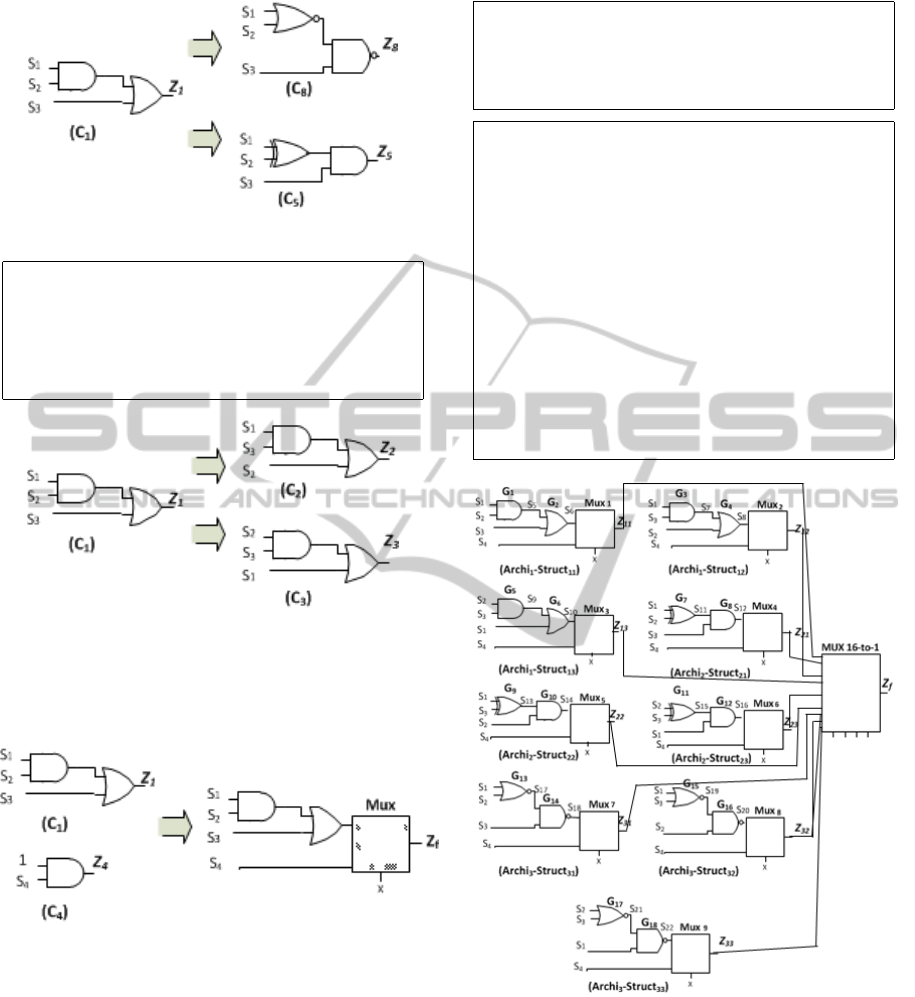
Figure 3: Architectural reconfiguration.
Running example 2:
Through the example given in Figure 4, we notice
that AND and OR gates are retained. Z
2
and Z
3
are
expressed as follows: Z
2
=S
1
.S
3
+S
2
; Z
3
=S
2
.S
3
+ S
1
Figure 4: Structural reconfiguration.
3) Data reconfiguration: consists in adding a mul-
tiplexer (data selector) in order to express the system
differently.
Figure 5: Data reconfiguration.
RHS is defined by the set of triples α, β and ϕ as
follows:
RHS ={α, β, ϕ } where α = {{components}}, β =
{{Signals}} and ϕ = {{Data}}.
At a given time (t), the system is characterized as
follows: RHS(t) = {X, Y, Z}, where X ∈ α ; Y ∈ β ; Z
∈ ϕ. X, Y and Z are respectively the set of gates, the
set of signals and the data set that have to implement
the system at a given time (t).
Let Ω be the initial fault list that contains all stuck-at
faults of the proposed system. Ω is initially equal to
108 faults.
Running Example 3:
In the example shown in Figure 5 , if x=0 then Z
f
=
S
1
.S
2
+S
3
. if x=1 then Z
f
=S
4
.
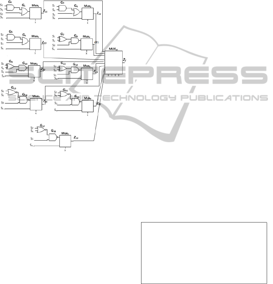
Running Example 4: Based on these scenar-
ios, the RHS example is composed of three
main architectures (Archi
1
, Archi
2
, Archi
3
). Each
architecture comprises three different structures
Struct
i j
, with 1 ≤ i ≤ 3 ; 1 ≤ j ≤ 3. Each struc-
ture can be expressed in terms of S
1
, S
2
and S
3
or
in terms of S
4
depending on input selection values.
16-to-1 Multiplexer is added to our model in order
to enable reconfigurations. Each circuit present-
ing the inputs of 16-to-1 multiplexer is expressing
architectural, structural and data reconfiguration.
For the totality of our system, we have 18 possible
reconfigurations as shown in Figure 6.
Figure 6: Reconfigurable Hardware System.
5 CONTRIBUTION: NEW
CHARACTERIZATION OF
FAULTS IN RHS
5.1 Classification of Faults
We define three new relations between faults: fault
PECCS2015-5thInternationalConferenceonPervasiveandEmbeddedComputingandCommunicationSystems
284

Running Example 5:
Continuing from the running example n4, α, β and
ϕ can take the following values:
α = {{G
1
(11), G
2
(11), Mux
1
(11)}, {G
3
(12),
G
4
(12), Mux
2
}, {G
5
(13), G
6
(13), Mux
3
(13)},
{G
7
(21), G
8
(21), Mux
4
(21)}, {G
9
(22), G
10
(22),
Mux
5
(22)}, {G
11
(23), G
12
(23), Mux
6
(23)},
{G
13
(31), G
14
(31), Mux
7
(31)}, {G
15
(32),
G
16
(32), Mux
8
(32)}, {G
17
(33), G
18
(33),
Mux
9
(33)}}
β ={{S
1
, S
2
, S
3
, S
4
, S
5
, S
6
, Z
11
}, {S
1
, S
2
, S
3
, S
4
,
S
7
, S
8
, Z
12
}, {S
1
, S
2
, S
3
, S
4
, S
9
, S
10
, Z
13
}, {S
1
,
S
2
, S
3
, S
4
, S
11
, S
12
, Z
21
}, {S
1
, S
2
, S
3
, S
4
, S
13
, S
14
,
Z
22
}, {S
1
, S
2
, S
3
, S
4
, S
15
, S
16
, Z
23
}, {S
1
, S
2
, S
3
, S
4
,
S
17
, S
18
, Z
31
},{S
1
, S
2
, S
3
, S
4
, S
19
, S
20
, Z
32
},{S
1
,
S
2
, S
3
, S
4
, S
21
, S
22
, Z
33
}}
ϕ= {{S
1
, S
2
, S
3
}, {S
4
}}
Running Example 6:
Continuing from the previous running example,
we suppose that the composition Archi
1
-Struct
11
with x=0, initially, implements the RHS then we
have
RHS(t
1
) = {{G
1
, G
2
, Mux
1
}, {S
1
, S
2
, S
3
, S
4
, S
5
,
S
6
, S
11
}, {S
1
, S
2
, S
3
}}.
At a given time t
2
, a change may affect the ar-
chitectural level. The Archi
2
-Struct
21
is deployed.
The RHS is expressed as follows:
RHS(t
2
) = {{G
7
, G
8
, Mux
4
}, {S
1
, S
2
, S
3
, S
4
, S
11
,
S
12
, Z
21
}, {S
1
, S
2
, S
3
}}.
At a given time t
3
, a structural reconfiguration can
occur: Archi
2
-Struct
23
is deployed.
RHS(t
3
) = {{G
7
, G
8
, Mux
4
}, {S
1
, S
2
, S
3
, S
4
, S
15
,
S
16
, Z
23
}, {S
1
, S
2
, S
3
}}.
Note that just internal signals are modified.
At t
4
, if the selector input x switch from x=0 to
x=1 then a data reconfiguration occurs.
RHS(t
4
) = {{G
7
, G
8
, Mux
4
}, {S
1
, S
2
, S
3
, S
4
, S
15
,
S
16
, Z
23
}, {S
4
}}
Inter-Equivalence, fault Inter-Dominance and fault
Redundancy.
Definition 1: Fault Inter-Equivalence
Let V
f
i
and V
f
j
be two sets of vectors that detect, re-
spectively, f
i
and f
j
. Two faults f
i
and f
j
in different
circuits C
i
and C
j
are said to be Inter-Equivalent (i)
if they are detected by exactly the same set of vec-
tors V
f
i
= V
f
j
, (ii) the input-output logic behaviors of
C
f
i
i
and C
f
j
j
are not necessary identical. If two faults
f
i
and f
j
are Inter-Equivalent, then only one of these
faults, say f
i
, needs to be retained in the fault list.
Definition 2: Fault Inter-Dominance
Let f
i
and f
j
be two faults in different circuits C
i
and
C
j
. Let V
f
i
be the set of all the vectors that detect
the fault f
i
. Similarly, let V
f
j
be the set of the vec-
tors that detect the fault f
j
. The Fault f
i
is said to
Inter-Dominate the fault f
j
(i) if V
f
i
contains V
f
j
that
means V
f
j
⊂ V
f
i
, (ii) the vectors that detect f
j
do not
necessary imply identical values at the corresponding
faulty outputs of C
f
i
i
and C
f
j
j
. If a fault f
i
dominates
a fault f
j
, then each vector that detects f
j
detects f
j
.
Therefore, f
i
can be deleted from the fault list.
Definition 3: Fault Redundancy
A fault f
i
is called redundant in different circuits C
i
and C
j
(i) if it is located at the same primary signal
used by the circuits C
i
and C
j
. If the fault appears in
the circuit C
i
, then it will also appear at the same sig-
nal of C
j
(ii) if the fault is at an internal signal of the
circuit C
i
and the same signal is present in C
j
, then f
i
is said to be redundant in C
i
and C
j
when f
i
is detected
by the same set of vectors. From the Redundancy
fault set, only one fault can be retained to represent
all faults in the corresponding fault set.
5.2 Application to Case Study:
Minimization of Faults for RHS
Consider the proposed system shown in Figure 6. It
has a total of 108 single stuck-at faults that can be re-
duced to 63 faults if we use the Intra-Equivalence and
the Intra-Dominance relationships. All faults collaps-
ing results are shown in Table 1: the number of col-
lapsed faults and the Collapse Ratio are given. The
latter is defined as (Bushnell, 2001):
Collapse Ratio =
seto f collapsed f aults
seto f all f aults
Table 1: Fault collapsing results.
Circuit name All faults
Number of collapsed faults
(Collapse Ratio)
Intra-Equivalence Intra-Dominance
Archi
1
-Struct
11
12 4(0.33) 2(0.16)
Archi
1
-Struct
12
12 4(0.33) 2(0.16)
Archi
1
-Struct
13
12 4(0.33) 2(0.16)
Archi
2
-Struct
21
12 2(0.16) 1(0.083)
Archi
2
-Struct
22
12 2(0.16) 1(0.083)
Archi
2
-Struct
23
12 2(0.16) 1(0.083)
Archi
3
-Struct
31
12 4(0.33) 2(0.16)
Archi
3
-Struct
32
12 4(0.33) 2(0.16)
Archi
3
-Struct
33
12 4(0.33) 2(0.16)
A collapse ratio around 0.4 is quite typical for
Intra-Equivalence and Dominance collapsing. How-
ever, considering Inter-circuits relationships, which is
NewSolutionsforOptimalHardwareTestsofReconfigurableHardwareSystems
285

the main topic of this paper, may provide smaller
collapsed fault set.
Inter-circuits fault collapsing reduces the number
of faults using three relationships among faults: Inter-
Equivalence, Inter-Dominance and Redundancy. For
Archi
1
, when comparing faulty versions of Struct
11
,
Struct
12
and Struct
13
, faults S
3
/1(12) from Struct
12
and S
3
/1(13) from Struct
13
are dropped since they
are Inter-Equivalent to S
2
/1(11) and S
1
/1(11) , respec-
tively. Also, faults S
3
/0 (11), S
2
/0(12) and S
1
/0(13)
are dropped since they Inter-Dominate S
1
/0(12),
S
1
/0(11) and S
1
/1(11), respectively. Faults S
1
/0(12),
S
1
/1(12), S
4
/0(12), S
4
/1(12), S
2
/1(13), S
4
/0(13) and
S
4
/1(13), which are derived from primary signals,
are dropped since they are redundant in Struct
12
and
Struct
13
. The remaining faults for Struct
11
are thus
S
1
/0, S
1
/1, S
2
/1, S
4
/0, S
4
/1. This set of faults cov-
ers all faults for Struct
12
. For Archi
1
-Struct
13
, only
the fault S
2
/0 remains. The same process is re-
peated for the other architectures. With respect to
the proposed model, our hierarchical approach to
fault collapsing is as follows: we first look for Inter-
Equivalence, Inter-Dominance and Redundancy rela-
tionships among all faults of different structures of
the same architecture. This process is called Intra-
Architecture fault collapsing. The latter is then fol-
lowed by Inter-Architectures fault collapsing where
we look for Inter-Equivalence, Inter-Dominance and
Redundancy relationships among remaining faults of
different architectures. By applying the proposed ap-
proach, we obtain the following results as shown in
Tables 2, 3 and 4. The Tables present, respectively,
Intra-Architecture fault collapsing results for Archi
2
,
Intra-Architecture fault collapsing results for Archi
3
and finally Inter-Architectures fault collapsing results
Table 2: Intra-Architecture fault collapsing results for
Archi
2
.
Initial fault list For:
Archi
2
-Struct
21
={S
1
/0, S
1
/1, S
2
/0, S
2
/1,
S
3
/0, S
3
/1, S
4
/0, S
4
/1, S
11
/1}
Archi
2
-Struct
22
={S
1
/0, S
1
/1, S
2
/0, S
2
/1,
S
3
/0, S
3
/1, S
4
/0, S
4
/1, S
13
/1}
Archi
2
-Struct
23
={S
1
/0, S
1
/1, S
2
/0, S
2
/1,
S
3
/0, S
3
/1, S
4
/0, S
4
/1, S
15
/1}
Number of collapsed faults (Collapse Ratio)
Inter-
Equivalence
Inter-
Dominance
Redundancy
2(0.074) 0(0.0) 14(0.51)
Remaining faults:
Archi
2
-Struct
21
={S
1
/0, S
1
/1, S
2
/0, S
2
/1,
S
3
/0, S
3
/1, S
4
/0, S
4
/1, S
11
/1}
Archi
2
-Struct
22
={S
13
/1}
Archi
2
-Struct
23
={S
15
/1}
for Archi
1
-Archi
2
-Archi
3
.
Table 3: Intra-Architecture fault collapsing results for
Archi
3
.
Initial fault list For:
Archi
3
-Struct
31
={S
1
/0, S
1
/1, S
2
/0, S
3
/1,
S
4
/0, S
4
/1}
Archi
3
-Struct
32
={S
1
/0, S
1
/1, S
2
/1, S
3
/0,
S
4
/0, S
4
/1}
Archi
3
-Struct
33
={S
1
/0, S
1
/1, S
2
/0, S
3
/0,
S
4
/0, S
4
/1}
Number of collapsed faults (Collapse Ratio)
Inter-
Equivalence
Inter-
Dominance
Redundancy
4(0.22) 0(0.0) 8(0.44)
Remaining faults:
Archi
3
-Struct
31
={S
1
/0, S
1
/1, S
2
/0, S
3
/1,
S
4
/0, S
4
/1}
Archi
3
-Struct
32
={}
Archi
3
-Struct
33
={}
Table 4: Inter-Architectures fault collapsing results for
Archi
1
-Archi
2
-Archi
3
.
Initial fault list For:
Archi
1
-Struct
11
={S
1
/0, S
1
/1, S
2
/1, S
4
/0,
S
4
/1}
Archi
1
-Struct
12
={}
Archi
1
-Struct
13
={S
2
/0}
Archi
2
-Struct
21
={S
1
/0, S
1
/1, S
2
/0, S
2
/1,
S
3
/0, S
3
/1, S
4
/0, S
4
/1, S
11
/1}
Archi
2
-Struct
22
={S
13
/1}
Archi
2
-Struct
23
={S
15
/1}
Archi
3
-Struct
31
={S
1
/0, S
1
/1, S
2
/0, S
3
/1,
S
4
/0, S
4
/1}
Archi
3
-Struct
32
={}
Archi
3
-Struct
33
={}
Number of collapsed faults (Collapse Ratio)
Inter-
Equivalence
Inter-
Dominance
Redundancy
1(0.04) 5(0.21) 9(0.39)
Remaining faults:
Archi
1
-Struct
11
={S
1
/0, S
1
/1, S
2
/1, S
4
/0,
S
4
/1}
Archi
1
-Struct
12
={}
Archi
1
-Struct
13
={S
2
/0}
Archi
2
-Struct
21
={S
11
/1}
Archi
2
-Struct
22
={}
Archi
2
-Struct
23
={}
Archi
3
-Struct
31
={S
3
/1}
Archi
3
-Struct
32
={}
Archi
3
-Struct
33
={}
The final fault list is thus {S
1
/0(11), S
1
/1(11),
S
2
/1(11), S
4
/0(11), S
4
/1(11), S
2
/0(13), S
11
/1(21),
PECCS2015-5thInternationalConferenceonPervasiveandEmbeddedComputingandCommunicationSystems
286

S
3
/1(31)}. Hence, by using Inter-Circuits fault col-
lapsing we are able to reduce the number of faults
from 63 to 8. This is, in effect, a 0.87 reduction
from the Intra-collapsing fault list which is divided
between 0.63 for Intra-Architecture fault collapsing
and 0.23 for Inter-Architecture fault collapsing.
In the next section, we propose the algorithms for
Inter-Circuits fault collapsing.
6 IMPLEMENTATION
Based on the new definitions of fault collapsing, we
present in this section the proposed algorithms. Let
F
A
= { f
A1
, f
A2
, . . . , f
An
} be the set of possible faults
in circuit C
A
. We suppose that T
A
is the list of po-
sitions of input values that generate different outputs
from the corresponding responses of the fault-free cir-
cuit C
A
. T
Ai
is the corresponding fault positions of
fault f
Ai
. Let F
B
= { f
B1
, f
B2
, . . . , f
Bn
} be the set of
possible faults in circuit C
B
and T
B
is the list of posi-
tions of faults for circuit C
B
. Algorithm 1 is developed
in order to reduce the set of faults between two cir-
cuits C
A
and C
B
using the Inter-Equivalence relation.
We propose algorithm 2 to decrease the fault set using
the Inter-Dominance relationship. Finally, algorithm
3 presents fault collapsing through the Redundancy
relation.
7 CONCLUSION AND FUTURE
WORK
In this paper, we propose three new fault collapsing
relations reducing faults from different circuits of the
RHS: fault Inter-Equivalence, fault Inter-Dominance
and fault Redundancy. This new classification of
faults reduces considerably the number of faults
which leads to optimize the set of vectors to be con-
sidered in the test generation. Consequently, we op-
timize the overall cost of the hardware test for the re-
configurable systems. In our future work, we plan to
continue our research with the Automatic Test Pattern
Generation (ATPG) for the RHS.
Algorithm 1: Inter Equivalence Fault Collapsing.
Inputs:
F
A
← { f
A1
, f
A2
, f
Ai
,. . . , f
An
}
i = 1 . . . k : the set of faults in C
A
T
A
← {T
A1
, T
A2
, T
Ai
,. . . , T
An
}
i = 1 . . . k : the list of positions of faults for C
A
F
B
← { f
B1
, f
B2
, f
B j
,. . . , f
Bn
}
j = 1 . . . h : the set of faults in C
B
T
B
← {T
B1
, T
B2
, T
B j
,. . . , T
Bn
}
j = 1 . . . h : the list of positions of faults for C
B
Inter equi← {equi list [line 1], equi list [line 2],. . . ,
equi list [line l]}; initially empty
Begin
For i = 1 . . . sizeof(T
A
)
For j = 1 . . . sizeof(T
B
)
if the elements in T
A
[i] are the same than
the elements in T
B
[j]
then add line in Inter equi
with F
A
[i]: top of the list [line]
F
B
[j]: end of the list [line]
Remove T
B
[j] from T
B
Remove F
B
[j] from F
B
End if
End For
End For
End
Algorithm 2: Inter Dominance Fault Collapsing.
Inputs:
F
A
← { f
A1
, f
A2
, f
Ai
,. . . , f
An
}
i = 1 . . . k : the set of faults in C
A
T
A
← {T
A1
, T
A2
, T
Ai
,. . . , T
An
}
i = 1 . . . k : the list of positions of faults for C
A
F
B
← { f
B1
, f
B2
, f
B j
,. . . , f
Bn
}
j = 1 . . . h : the set of faults in C
B
T
B
← {T
B1
, T
B2
, T
B j
,. . . , T
Bn
}
j = 1 . . . h : the list of positions of faults for C
B
Inter dom← {dom list [line 1], dom list [line 2],. . . ,
dom list [line l]}; initially empty
Begin
For i = 1 . . . sizeof(T
A
)
For j = 1 . . . sizeof(T
B
)
if the elements in T
A
[i] ⊂ T
B
[j]
then add line in Inter dom
with F
A
[i]: top of the list [line]
F
B
[j]: end of the list [line]
Remove T
B
[j] from T
B
Remove F
B
[j] from F
B
End if
End For
End For
End
NewSolutionsforOptimalHardwareTestsofReconfigurableHardwareSystems
287

Algorithm 3: Redundancy Fault Collapsing.
Inputs:
F
A
← { f
A1
, f
A2
, f
Ai
,. . . , f
An
}
i = 1 . . . k : the set of faults in C
A
T
A
← {T
A1
, T
A2
, T
Ai
,. . . , T
An
}
i = 1 . . . k : the list of positions of faults for C
A
F
B
← { f
B1
, f
B2
, f
B j
,. . . , f
Bn
}
j = 1 . . . h : the set of faults in C
B
T
B
← {T
B1
, T
B2
, T
B j
,. . . , T
Bn
}
j = 1 . . . h : the list of positions of faults for C
B
Redundancy List:initially empty
Begin
SignalsA ← Extract signals from F
A
where Sig-
nalsA[i]
is the corresponding signals used by F
A
[i]
SignalsB ← Extract signals from F
B
where SignalsB[j]
is the corresponding signals used by F
B
[j]
For i = 1 . . . sizeof(F
A
)
For j = 1 . . . sizeof(F
B
)
if F
A
[i] is the same than F
B
[j]
if the corresponding SignalsA[i] and SignalsB[j]
are the same primary signal
then add line in Redundancy List
with F
A
[i]: top of the list [line]
F
B
[j]: end of the list [line]
Remove T
B
[j] from T
B
Remove F
B
[j] from F
B
Remove SignalsB[j] from SignalB
else
if the elements in T
A
[i] are the same than
the elements in T
B
[j]
then add line in Redundancy
List
with F
A
[i]: top of the list [line]
F
B
[j]: end of the list [line]
Remove T
B
[j] from T
B
Remove F
B
[j] from F
B
Remove SignalsB[j] from SignalB
End if
End For
End For
End
REFERENCES
Abramovici, M. and Menon, P. R. (1997). Fault simula-
tion on reconfigurable hardware. In 5th IEEE Sympo-
sium on Field-Programmable Custom Computing Ma-
chines (FCCM ’97), 16-18 April 1997, Napa Valley,
CA, USA, pages 182–191.
Agrawal, V. D., Prasad, A. V. S. S., and Atre, M. V. (2003).
Fault collapsing via functional dominance. In ITC,
pages 274–280.
Ahmadinia, A. (2007). Optimal free-space manage-
ment and routing-conscious dynamic placement for
reconfigurable devices. IEEE Trans. Computers,
56(5):673–680.
Al-Asaad, H. and Lee, R. (2002). Simulation-based approx-
imate global fault collapsing.
Angelov, C., Sierszecki, K., and Marian, N. (2005). De-
sign models for reusable and reconfigurable state ma-
chines. In EUC, pages 152–163.
Bushnell, M. L. (2001). Essentials of electronic testing for
digital, memory and mixed-signal vlsi circuits.
Gharbi, A., Khalgui, M., and Ahmed, S. B. (2010). Op-
timal model checking of safe control embedded soft-
ware components. In Proceedings of 15th IEEE Inter-
national Conference on Emerging Technologies and
Factory Automation, ETFA 2010, September 13-16,
2010, Bilbao, Spain, pages 1–8.
Khalgui, M. (2010). Nces-based modelling and ctl-based
verification of reconfigurable embedded control sys-
tems. Computers in Industry, 61(3):198–212.
Prasad, A. V. S. S., Agrawal, V. D., and Atre, M. V. (2002).
A new algorithm for global fault collapsing into equiv-
alence and dominance sets. In ITC, pages 391–397.
Rooker, M. N., Snder, C., Strasser, T., Zoitl, A., Hummer,
O., and Ebenhofer, G. (2007). Zero downtime recon-
figuration of distributed automation systems: The ep-
siloncedac approach. In Mavrk, V., Vyatkin, V., and
Colombo, A. W., editors, HoloMAS, volume 4659 of
Lecture Notes in Computer Science, pages 326–337.
Springer.
Sethuram, R., Bushnell, M. L., and Agrawal, V. D.
(2008). Fault nodes in implication graph for
equivalence/dominance collapsing, and identifying
untestable and independent faults. In 26th IEEE VLSI
Test Symposium (VTS 2008), April 27 - May 1, 2008,
San Diego, California, USA, pages 329–335.
Steininger, A. (2000). Testing and built-in self-test - a sur-
vey. Journal of Systems Architecture, 46(9):721–747.
Veneris, A. G., Chang, R., Abadir, M. S., and Amiri, M.
(2004). Fault equivalence and diagnostic test genera-
tion using atpg. In ISCAS (5), pages 221–224.
PECCS2015-5thInternationalConferenceonPervasiveandEmbeddedComputingandCommunicationSystems
288
