
An Online Vision System for Understanding Complex Assembly Tasks
Thiusius Rajeeth Savarimuthu
1
, Jeremie Papon
2
, Anders Glent Buch
1
, Eren Erdal Aksoy
2
,
Wail Mustafa
1
, Florentin W
¨
org
¨
otter
2
and Norbert Kr
¨
uger
1
1
Maersk Mc-Kinney Moller Institute, University of Southern Denmark, Odense, Denmark
2
Department for Computational Neuroscience, Georg-August-Universit
¨
at G
¨
ottingen, G
¨
ottingen, Germany
Keywords:
Tracking, Monitoring, Robotics.
Abstract:
We present an integrated system for the recognition, pose estimation and simultaneous tracking of multiple
objects in 3D scenes. Our target application is a complete semantic representation of dynamic scenes which
requires three essential steps; recognition of objects, tracking their movements, and identification of interac-
tions between them. We address this challenge with a complete system which uses object recognition and
pose estimation to initiate object models and trajectories, a dynamic sequential octree structure to allow for
full 6DOF tracking through occlusions, and a graph-based semantic representation to distil interactions. We
evaluate the proposed method on real scenarios by comparing tracked outputs to ground truth trajectories and
we compare the results to Iterative Closest Point and Particle Filter based trackers.
1 INTRODUCTION
Fast and reliable interpretation of complex scenes by
computer vision is still a tremendous challenge. De-
velopment in manufacturing procedures require vi-
sion systems to cope with versatile and complex sce-
narios within a fast changing production chain (Zhang
et al., 2011). Many of the assembly processes to-
day can be described by object identities and their
spatiotemporal relation in the semantic level (Aksoy
et al., 2011; Yang et al., 2013; Ramirez-Amaro et al.,
2014). Hence, object detection and persistence as
well as pose estimation are vital in order to automati-
cally detect and classify assembly processes.
Figure 1 shows a scene where multiple objects of
uniform and identical color are presented to the vision
system. Monitoring of such state spaces is important,
e.g., for the execution of assembly tasks performed by
robots, as we are investigating in the industrial work-
cell MARVIN (see Figure 2). This monitoring allows
for the detection of preconditions for robot actions to
be performed as well as for the evaluation of individ-
ual robot actions. In our setup, we restrict ourselves
to table top scenarios, where rigid objects are manip-
ulated in different ways.
Recently, Semantic Event Chains (SECs) (Ak-
soy et al., 2011) have been introduced as a mid-
level representation for action sequences. SECs en-
code “the essence of action sequences” by means of
touching relations between objects in so-called key-
frames. SECs—in addition to a graph with touching
relations—include object identity and object pose in-
formation fed from the lower level modules. Hence
detecting object identities and tracking the poses of
these objects are required in order to enrich SECs
and relate them to actions. However, it is neither
possible nor required to compute object identity and
pose information continuously. It is not possible due
to limited computational resources and it is not re-
quired, since the object identity does not change ar-
bitrarily. Furthermore, exact pose estimation is only
required in particular situations, e.g. when an assem-
bly action is performed. As such, it is sufficient to
initialize a tracking system using a precise detection
and pose estimation system, and then maintain ob-
ject pose using the tracker. The tracked output can be
used to detect when key-frames occur and more pre-
cise (or interaction-specific) pose and object-identity
information are needed.
One important aspect required in such a system is
object persistence through occlusions, as in even sim-
ple assembly tasks components will often become oc-
cluded by the person performing the assembly. This
is of particular importance to the system described
above, as losing object identity makes it impossi-
ble to recover an accurate semantic understanding
of observed actions. While recent 3D tracking ap-
proaches address the issue of run-time performance
454
Savarimuthu T., Papon J., Buch A., Aksoy E., Mustafa W., Wörgötter F. and Krüger N..
An Online Vision System for Understanding Complex Assembly Tasks.
DOI: 10.5220/0005260804540461
In Proceedings of the 10th International Conference on Computer Vision Theory and Applications (VISAPP-2015), pages 454-461
ISBN: 978-989-758-091-8
Copyright
c
2015 SCITEPRESS (Science and Technology Publications, Lda.)
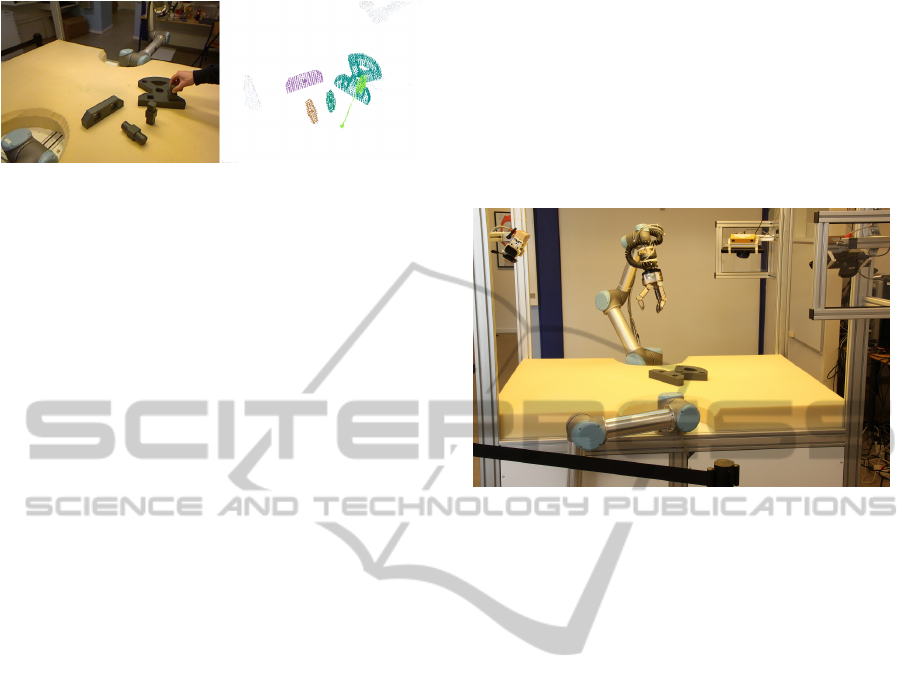
Figure 1: Left: intermediate frame of a complex assembly
scene where one of many peg in hole operations is being
performed. Right: detection and tracking output.
by offloading processing to a GPU (Choi and Chris-
tensen, 2013), or accurate 3D reconstruction of sin-
gle targets (Ren et al., 2013), in this work we focus
on maintaining tracks of multiple interacting objects
even in the presence of long durations of full occlu-
sions.
In this paper, we describe a system which is able
to compute a semantic representation of complex
scenes. In particular, we propose a tracking and mon-
itoring system with bottom-up initialisation of the
tracking and top-down enrichment of the scene rep-
resentation. The main processing backbone for con-
necting the object-specific recognition and pose es-
timation systems with the object-invariant SEC rep-
resentations is the tracking system proposed by (Pa-
pon et al., 2013). Motivated by the particular im-
portance of the parallel tracking of multiple objects
in this work, we compare the proposed tracking sys-
tem with a naive tracking method (ICP), a comparable
tracking method (particle filter) and to a “ground truth
tracking” by magnetic sensors in order to demonstrate
the superior occlusion-handling of our system.
We show that by using assumptions on object per-
manence and efficiently combining low-level tracking
and pose estimation, we are able to extract the struc-
ture of a complex scene with multiple moving objects
with partly significant occlusions in real-time.
2 SYSTEM OVERVIEW
We describe the complete system – both on a hard-
ware and a software level – to explain the context in
which the tracker operates. We start by shortly de-
scribing our test platform, followed by a description
of the different perception modules and their interac-
tion.
The MARVIN platform is a robotic platform de-
signed to simulate industrial assembly tasks (see Fig-
ure 2 and (Savarimuthu et al., 2013)). The setup
includes both perception and manipulation devices.
The perception part includes three sets of vision sen-
sors, each set consisting of a Bumblebee2 stereo cam-
era and a Kinect sensor. The three camera sets are
placed with approx. 120
◦
separation, as shown in
Figure 2. In addition to the cameras, the platform
is also equipped with high-precision trakSTAR mag-
netic trackers capable of providing 6D poses simulta-
neously from up to four sensors. In this paper, we use
one Kinect and the trakSTAR sensors for the evalua-
tion of the tracker results (see Sect. 4).
Figure 2: The robotic MARVIN platform with two manip-
ulators and three camera pairs.
2.1 Interaction of Modules
The proposed system has four modules: object recog-
nition, pose estimation, tracking and SEC extraction.
The system is initialized by the first two modules in
combination. Correct detection of objects is crucial
to the performance of the running system, but also
requires a high amount of computational resources.
Therefore, after the detection of objects, the real-time
tracker maintains the pose of the objects. Based on
the (tracked) state of the scene, the SEC extractor
maintains a meaningful high-level representation of
the scene. As soon as the state of the scene changes
due to newly formed or terminated object relations, a
reinitialization of the tracker is required, since at these
key-frames the appearance of objects may change in
a non-smooth manner, e.g., by sudden occlusions.
The SEC module detects key-frames and propa-
gates the information to the tracker, which in turn in-
vokes the pose estimation module for a robust reini-
tialization of object pose(s). No object recognition is
required at this point, since the object identities have
been preserved by the tracker, and only the objects in-
volved in the changed relation are reinitialized. The
pose reinitialization is performed using an optimized
local pose estimation routine. Consequently, there are
multiple dependencies in both directions between the
different modules. Object identities and poses are sent
“up” for the tracking of objects and the SEC extrac-
tion, whereas higher-level relations are sent “down”
AnOnlineVisionSystemforUnderstandingComplexAssemblyTasks
455

to strengthen the tracking. See Figure 3 for an illus-
tration. All modules are detailed in the following sec-
tion.
The object recognition, pose estimation and track-
ing modules are all directly involved in the extraction
and preservation of explicit object information (iden-
tity and pose) for parts in the scene. The last mod-
ule (SEC) operates at a higher level and integrates
the knowledge about all objects into a coherent scene
representation. Based on this system, we are able to
track multiple object with a framerate of 15hz during
robotic assembly. The image on the left of Figure 4
shows the full tracking history of 9 objects. The col-
ored lines marks the path of the induvidual object dur-
ing assembly. The top right image of Figure 4 shows
the last SEC representation of the scene. Here all the
objects are identified and have thier labels attached.
Figure 3: Schematic of the four modules.
3 MODULE DESCRIPTION
3.1 Geometry-based Object Recognition
and Pose Estimation
At the very first frame of a sequence, we apply robust
object recognition and pose estimation techniques to
extract the identity and location of each object present
in the scene. Both modules operate on a special-
ized set of 3D feature points called texlets, which are
used for representing local surfaces (Kootstra et al.,
2012). The texlet representation significantly reduces
the number of data points compared to, e.g., a point
cloud representation and provides a good trade-off be-
tween completeness and condensation.
The texlet representation has previously been ap-
plied by (Mustafa et al., 2013) for recognition and by
(Buch et al., 2013) for pose estimation of 3D objects
containing varying degrees of distinct appearance
(texture) and geometry (non-planar surfaces), both for
single- and multi-view observations of scenes. For
completeness, we shortly outline these methods be-
low, as they are used in the respective modules.
Our approach stands in contrast with regular point
cloud based detection systems in which local fea-
tures capture geometric statistics (Tombari et al.,
2010), and where feature points are either selected
uniformly or randomly (Drost et al., 2010; Aldoma
et al., 2012). Instead, we use detected feature points
and local features capturing both geometry and ap-
pearance.The object recognition system is based on
a Random Forest (RF) classifier, which is applied to
a high-dimensional feature space, given by a two-
dimensional histogram computed globally on an ob-
ject surface represented by texlets. The histogram
entries are computed by binary geometric relations
between texlet pairs. Since texlets are much more
sparse than, e.g., point clouds, we sample all possi-
ble texlet pairs on the reconstructed object surface.
Each object model is now represented by a geome-
try histogram, as follows. Between every sampled
texlet feature pair, we extract the relative angle be-
tween the surface normals, and the normal distance,
i.e., the point to plane distance between the one texlet
and the plane spanned by the other texlet in a pair.
We bin all pairs into a 2D angle-distance histogram,
and get the final geometry descriptor vector by plac-
ing all rows in the histogram in a single array. This
histogram provides a highly discriminative object rep-
resentation, which is fed to the RF classifier. This
method requires the objects in the scene to be sepa-
rable by segmentation in order to initially extract the
full texlet representation of the object. For each rec-
ognized segment in the scene, we now execute a ro-
bust feature-based pose estimationThis method uses
local histogram descriptors computed in a local region
around each texlet, defined by a support radius. Pose
estimation is done by a check of the geometric con-
sistency between the triangle formed on the object by
the sample points and the triangle formed in the scene
by the matched feature points. We refer the reader to
(Buch et al., 2013) for further details and evaluations
of this method. This method has also been accepted
in the Point Cloud Library (PCL)(Rusu and Cousins,
2011), and is available since version 1.6 in the class
SampleConsensusPrerejective.
3.2 Proposed Tracker
Tracking takes advantage of a novel Sequential
Adjacency-Octree (SATree), also publicly available
as part of the PCL. This is a dynamic octree struc-
ture which was first introduced by (Papon et al., 2013)
in order to achieve object permanence and maintain
VISAPP2015-InternationalConferenceonComputerVisionTheoryandApplications
456
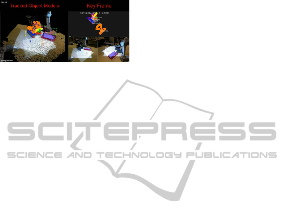
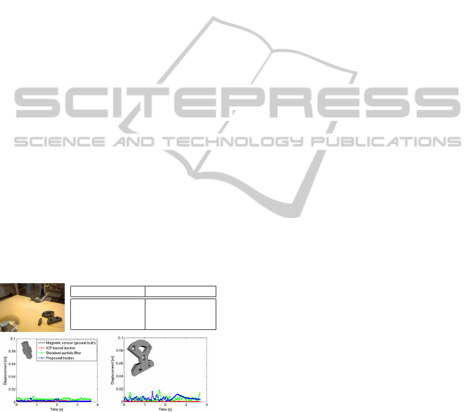
Figure 4: The scene interpretation. Left panel: The trac-
ing history of the individual objects represented by coloured
threads. Top right panel: Scene representation on the level
of Semantic Event Chains. Bottom left: Two of the cameras
recording the scene.
object tracks through lengthy full occlusions. Points
are added into this tree structure through a three stage
process. Starting with an existing tree (i.e. from the
first frame), we first insert the newly observed points
into the octree, and initialize new leaves for them if
they did not exist previously. This results in an octree
where leaves fall into three possible categories; they
are either new, observed, or unobserved in the most
recent observation. Handling of new and observed
leaves is straightforward; we simply calculate adja-
cency relations for their voxels to existing leaves. Of
more importance is how to handle leaves which were
not observed in the inserted point cloud. Rather than
simply prune them, we first check if it was possible to
observe them from the viewpoint of the sensor which
generated the input cloud. This occlusion check can
be accomplished efficiently using the octree by deter-
mining if any voxels exist between unobserved leaves
and the sensor viewpoint. If a clear line of sight exists
from the leaf to the camera, it can safely be deleted.
Conversely, if the path is obstructed, we “freeze” the
leaf, meaning that it will remain constant until it is ei-
ther observed or passes the line of sight test in a future
frame (in which case, it can be safely deleted). In or-
der to account for objects moving towards the camera,
we additionally check if an unobserved occluded leaf
has any new leaves adjacent to it. If so, and one of
these adjacent leaves is responsible for the occlusion,
we prune it. This occlusion testing means that track-
ing of occluded objects is trivial, as occluded voxels
remain in the observations which are used for track-
ing. We should note that this reasoning assumes that
occluded objects do not move significantly while be-
ing fully occluded. Tracking of the segmented models
is accomplished using a bank of independent parallel
particle filters. The models consist of clouds of vox-
els, and observations are the voxel clouds produced
by the SATree. The measurement model transforms
model voxels using predicted state (x, y, z, roll, pitch,
yaw), and then determines correspondences by asso-
ciating observed voxels with nearest voxels from the
transformed models. Distance between correspond-
ing voxels is measured in a feature space of spatial
distance, normals, and color (in HSV space). These
correspondence distances are then combined into an
overall weight for each particle. We use a constant ve-
locity motion model, but do not include velocity terms
in the state vector, as this would double the dimen-
sionality of the state-vector (negatively affecting run-
time performance). Instead we use a “group-velocity”
which uses the overall estimated state from the previ-
ous time-step to estimate the velocity. This allows us
to track motions smoothly without the need to add ve-
locity state terms to each particle.
KLD sampling (Fox, 2003) is used to dynamically
adapt the number of particles to the certainty of pre-
dictions. This works well in practice due to the use of
the persistent world model from the SATree, meaning
that very little computational power is needed to track
models which are static (or occluded), as the target
distribution has only small changes and therefore can
be approximated well using only a small particle set.
Details of the particle filters themselves are beyond
the scope of this work, but we refer the reader to (Fox,
2003) for an in-depth description of their operation.
For this work, we rely on the fact that the particle fil-
ters yield independent predictions of 6D object states,
allowing a transformation of the model to the current
time-step, roughly aligning it with the currently ob-
served world voxel model.
3.2.1 Pose Refinement for Reinitialization
The object recognition combined with the pose esti-
mation addresses the problem of identifying the ob-
jects present in the scene, while the tracker seeks to
maintain these identities during movement. As will
be presented in the following section, we are addition-
ally able to detect object collisions, which can desta-
bilize the tracking process. At these time instances,
we apply a customized ICP (Besl and McKay, 1992),
initialized with the current tracker pose, to the objects
involved in the collision. For efficiency, we resam-
ple the point clouds of the objects and the scene to a
coarse resolution of 5 mm. We set an inlier threshold
of twice this resolution for associating nearest point
neighbors in each iteration, and we terminate the ICP
loop prematurely if the relative decrease in the RMS
point to point alignment error becomes too low. These
modifications ensure convergence to a good solution,
while avoiding the risk of running for too many itera-
tions.
AnOnlineVisionSystemforUnderstandingComplexAssemblyTasks
457
3.3 Semantic Event Chain
The SEC was recently introduced as a possible
descriptor for manipulation actions (Aksoy et al.,
2011). The SEC framework analyzes the sequence of
changes of the spatial relations between the objects
that are being manipulated by a human or a robot.
The SEC framework first interprets the scene as undi-
rected and unweighted graphs, nodes and edges of
which represent segments and their spatial relations
(e.g. touching or not-touching), respectively. Graphs
hence become semantic representations of segments,
i.e. objects present in the scene (including hands),
in the space-time domain. The framework then dis-
cretizes the entire graph sequence by extracting only
main graphs, each of which represents essential prim-
itives of the manipulation. All extracted main graphs
form the core skeleton of the SEC which is a se-
quence table, where the columns and rows correspond
to main graphs and spatial relational changes between
each object pair in the scene, respectively. SECs con-
sequently extract only the naked spatiotemporal pat-
terns which are the essential action descriptors, invari-
ant to the followed trajectory, manipulation speed, or
relative object poses. The resulting SECs can be eas-
ily parsed for the detection of key-frames in which
object collisions/avoidances occur, simply by check-
ing if touching relations have appeared/disappeared.
This in turn allows us to determine when to perform
reinitialization of object poses for the tracker, as de-
scribed in the previous section. Figure 4 top right
image shows the SEC representation of the assembly
scene shown in the two bottom right images.
Tracker Frame rate [Hz]
ICP tracker 1.92
Std particle filter 25.6
Proposed tracker 31.8
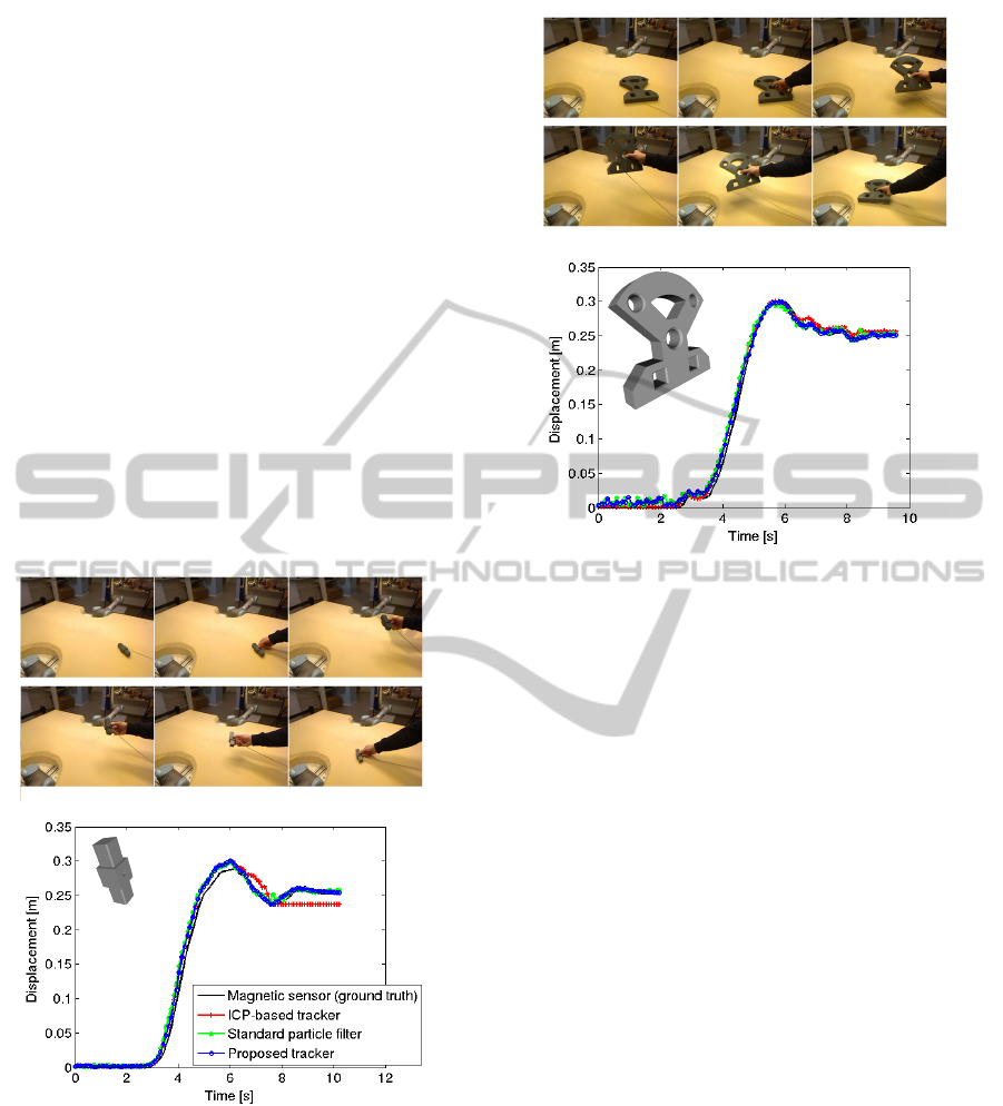
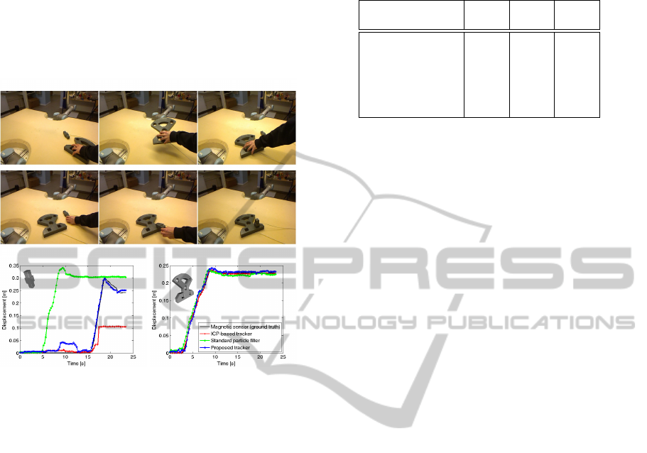
Figure 5: Results for the control sequence, where two ob-
jects are lying still for the whole duration. Top: first frame
of the sequence and timing benchmark, averaged over the
full sequence. Bottom: recorded trajectories for the se-
quence.
4 EXPERIMENTS
For evaluations, we have carried out experiments to
assess the performance of the proposed tracker, since
the tracker represents the backbone of the online mon-
itoring system. Importantly, we note that full-scale
recognition and pose estimation experiments are not
the key aspect of this paper, and we thus refer the
reader to previous works (Mustafa et al., 2013; Buch
et al., 2013). We evaluate our tracking method using a
set of real sequences with thousands of frames, show-
ing manipulation of different objects. The first exper-
iment is a sensitivity analysis of the noise level of the
tracker, and all the following experiments are done
on sequences with varying degrees of movement. In
a final qualitative experiment, we show how the pre-
sented system performs on a complex assembly se-
quence involving multiple objects.
We have implemented two baseline trackers for
quantitative comparison of our system, an ICP-based
tracker and a point cloud based particle filter tracker.
This former is a straightforward application of the
modified ICP algorithm described in Sect. 3.2.1 into
a tracking context. The use of ICP during track-
ing has been successfully applied in other works,
e.g. the KinectFusion algorithm (Newcombe et al.,
2011). Our ICP-based tracker simply updates the ob-
ject pose from frame to frame using the previously
described ICP algorithm. While our tracker shows
near real-time performance, the ICP-based tracker has
a much lower frame rate due to the geometric verifica-
tion, making it unsuitable for practical usage. While
the ICP algorithm is expected to produce an optimal
alignment in terms of RMS point to point error in sim-
ple scenarios, in realistic scenarios with clutter and
occlusions it will tend to fail by switching to clutter
or occluders. Even worse, if tracked objects are dis-
placed by a large distance from one frame to another,
the ICP tracker will inevitably fail, due to its very nar-
row convergence basin. The second tracker we com-
pare against is a slightly modified version of the stan-
dard point cloud based particle filter previously avail-
able as part of the PCL. The modifications include
optimizations for run-time performance in the multi-
object case, as well as improvements to the measure-
ment function.
4.1 Evaluation Metrics
For the evaluation of the different methods, we com-
pare the relative displacements recorded during a
tracked trajectory. As all sequences start with objects
lying still on the table, we use the first 5 % tracked
poses to find a mean pose. The rotation mean is taken
VISAPP2015-InternationalConferenceonComputerVisionTheoryandApplications
458
by matrix addition of the rotation matrices, followed
by an orthogonalization using singular value decom-
position. This pose is regarded as the intial pose of
the object relative to the tracking system. We now
take the relative pose in each tracked time instance to
this pose to get a displacement in SE(3) relative to
the starting point. The translation component of this
pose implicitly reflects both the positional displace-
ment and the angular displacement, and thus quantify
the displacement in that time instance by the norm of
this translation. All plots shown below are created us-
ing this procedure. We consider the trakSTAR trajec-
tories as ground truth, since they show very low rela-
tive errors in µm range. To quantify the tracking er-
ror, we take the RMS error between the displacement
reported by the tracker and the ground truth displace-
ment. We also note that in all graphs presented in the
following sections, equidistant data point markers are
added to the plots for the sake of clarity; thus, they do
not reflect the frequency of the data points used for
plotting the curves, which is much higher.
Figure 6: Results for the simple sequences. The object is
moved along a circular arc during manipulation.
In an initial experiment, we investigate the sensi-
tivity and computational complexity of the three im-
plemented trackers. As the ICP tracker always seeks
to minimize an objective function, it is expected to
converge consistently to the same solution, whereas
the randomized nature of the particle filter trackers
make them more imprecise, but allowing for higher
robustness towards large displacements. All results
of the experiment are shown in Figure 5. The ICP
Figure 7: Results for the simple sequences. The object is
moved along a circular arc during manipulation.
method provides very stable results for this very con-
trolled scenario. Referring to the two top rows in
Tab. 1, this is validated by the numbers, which shows
a RMS error of 0.95 mm for the bolt and 0.35 mm
for the faceplate (CAD models of both objects, belt
and face plate, are shown in the two lower subfigures
in figure 5 in the upper left corner). The lower error
of the large faceplate can be explained by the simple
fact that the higher number of points in the model al-
lows for a higher robustness against point outliers in
the alignment process. For the particle filter track-
ers, however, this behavior is reversed. These track-
ers sample poses in SE(3) around the current estimate
to widen the convergence basin, and select the best
candidate. For large objects, perturbations in the ro-
tations have larger effect on the resulting alignment,
making the error higher for the faceplate in this case.
The errors for the proposed tracker are 1.4 mm and
5.9 mm (see table 1 first two lines), respectively, but
this is achieved in less than 1/15
th
of the time. In ad-
dition, as we will show below, the proposed tracker
is more stable than both the ICP-based tracker and a
standard particle filter tracker. We also note that the
timings shown in Figure 5 are best case results, since
during fast changing poses, the adaptive sampling can
lead to multiple pose candidates for validation.
In the second test (see figure 6 and 7) we perform
a very simple movement of a single object each. We
again tested the small bolt and the larger faceplate and
observed similar results. Notably, the ICP tracker per-
AnOnlineVisionSystemforUnderstandingComplexAssemblyTasks
459
forms worse in the final stage of the bolt sequence (see
Figure 6) compared to the face plate sequence (see
Figure 7). This occurs due to the ICP tracker assign-
ing false point correspondences, i.e., the full model
is fitted suboptimally to the incomplete scene data.
We now show by a simple peg in hole sequence how
Figure 8: Results for a peg in hole assembly sequence. See
text for details.
both the baseline trackers completely fail under oc-
clusions. In this sequence, the human arm and the
large faceplate are moved initially in such a way that
they temporarily occlude the bolt completely. In this
period, both the ICP and the standard particle filter
trackers fail: the ICP tracker stops functioning be-
cause it cannot associate point correspondences (be-
cause all points close to the model are occluded), and
the particle filter—being more global—finds a false
alignment on the table and stays there. Our tracker,
however, is able to cope with this situation by the oc-
clusion reasoning outlined in section 3.2. When the
occlusion initally occurs, the object displaces a bit,
since the tracker can only provide a suboptimal align-
ment due to the increasing level of occlusion. Af-
ter a short while, the occlusion is detected, and the
tracker maintains the object identity in a static pose
until the region in space becomes visible again. The
occlusion part of the sequence is visible in the left-
most plot in Figure 8 at approx. 5-13 s into the se-
quence. In these sequences, we also observe the ef-
fect of the pose reinitialization, made possible by the
higher-level SEC detection of key-frames. In the fi-
nal insertion stage of the bolt, at approx. 22 s, the
proposed tracker “undershoots” by approx. 20 mm.
The pose reinitialization is invoked, and the alignment
improves, until the tracker settles at a displacement
Table 1: RMS errors for the test sequences. The static se-
quence results reflect the steady state tracker noise levels.
Seq. (object) ICP Std. Prop.
[mm] [mm] [mm]
Static (bolt) 0.95 2.3 1.4
Static (f.plate) 0.35 5.7 5.9
Simple (bolt) 13 12 8.9
Simple (f.plate) 7.7 10 7.1
Assemb. (bolt) 81 198 17
Assemb. (f.plate) 2.5 9.1 5.4
with an overshoot of approx. 5 mm. The reinitial-
ization is also visible at the same time in the face-
plate sequence, where a slight overshoot occurs dur-
ing insertion. After the reinitialization of the faceplate
pose, the tracker settles at a displacement very close
to ground truth.
For all the previous experiments, we quantify the
errors relative to the trakSTAR trajectories, as ex-
plained in Sect. 4.1. In general, our tracker outper-
forms the standard particle filter tracker, whereas in
most cases ICP provides the optimal fit, but at the ex-
pense of a significant increase in computational time.
Results are shown in Tab. 1.
We finalize our evaluation by presenting a more
realistic and complex assembly involving multiple
objects. For this experiment, we had to remove the
magnetic sensors, otherwise they would obstruct cer-
tain parts of the objects, making assembly impossible.
Therefore we present only qualitative results in Fig-
ure 9 where the tracked poses of the objects are shown
as coloured lines. Note that the bolts are maintained
in the model even after heavy occlusions, visible pri-
marily in the last frame. We also note that the human
arm causes several occlusions during the sequence.
5 CONCLUSIONS
In this paper, we have addressed the non-trivial prob-
lem of maintaining the identities and poses of several
recognized objects in 3D scenes during manipulation
sequences. We have implemented and successfully
tested a bidirectional feedback structure to initialize
and maintain object identity and pose. By that we
were able to compute a semantic scene representation
with multiple independently moving objects which
has been used for action monitoring. We sompared
our tracking algorithm to a baseline implementation
of an ICP-based tracker. By that we were able to show
that our tracking method provides a speedup of more
than 15 times with a superior performance on com-
plex scenes. When compared our tracking also with
a standard particle filter and showed that our method
VISAPP2015-InternationalConferenceonComputerVisionTheoryandApplications
460
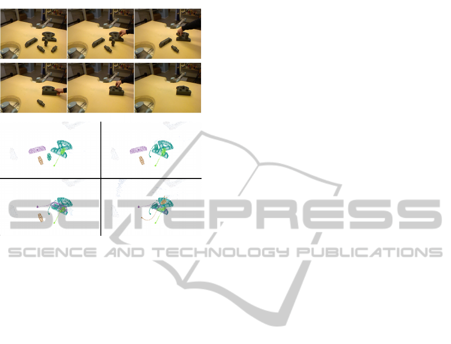
Figure 9: Tracker results for a complex assembly sequence.
The bottom images show the tracked object models, rep-
resented by point clouds, at the key-frames which are also
shown in the four intermediate top images.
shows a higher degree of robustness to disturbances
in the form of both partial and total occlusions.
ACKNOWLEDGEMENTS
This work has been funded by the EU project ACAT
(ICT-2011.2.1, grant agreement number 600578) and
the DSF project patient@home.
REFERENCES
Aksoy, E. E., Abramov, A., D
¨
orr, J., Ning, K., Dellen,
B., and W
¨
org
¨
otter, F. (2011). Learning the semantics
of object-action relations by observation. The Inter-
national Journal of Robotics Research, 30(10):1229–
1249.
Aldoma, A., Tombari, F., Di Stefano, L., and Vincze, M.
(2012). A global hypotheses verification method for
3d object recognition. In Computer Vision–ECCV
2012, pages 511–524. Springer.
Besl, P. and McKay, N. D. (1992). A method for registration
of 3-d shapes. PAMI, 14(2):239–256.
Buch, A., Kraft, D., Kamarainen, J.-K., Petersen, H.,
and Kr
¨
uger, N. (2013). Pose estimation using local
structure-specific shape and appearance context. In
ICRA, pages 2080–2087.
Choi, C. and Christensen, H. (2013). Rgb-d object track-
ing: A particle filter approach on gpu. In Intelligent
Robots and Systems (IROS), 2013 IEEE/RSJ Interna-
tional Conference on.
Drost, B., Ulrich, M., Navab, N., and Ilic, S. (2010). Model
globally, match locally: Efficient and robust 3d object
recognition. In Computer Vision and Pattern Recogni-
tion (CVPR), 2010 IEEE Conference on, pages 998–
1005. IEEE.
Fox, D. (2003). Adapting the sample size in particle filters
through kld-sampling. The International Journal of
Robotics Research, 22(12):985–1003.
Kootstra, G., Popovic, M., Jørgensen, J., Kuklinski, K., Mi-
atliuk, K., Kragic, D., and Kruger, N. (2012). En-
abling grasping of unknown objects through a syner-
gistic use of edge and surface information. The Inter-
national Journal of Robotics Research, 31(10):1190–
1213.
Mustafa, W., Pugeault, N., and Kr
¨
uger, N. (2013). Multi-
view object recognition using view-point invariant
shape relations and appearance information. In ICRA,
pages 4230–4237.
Newcombe, R. A., Davison, A. J., Izadi, S., Kohli, P.,
Hilliges, O., Shotton, J., Molyneaux, D., Hodges, S.,
Kim, D., and Fitzgibbon, A. (2011). Kinectfusion:
Real-time dense surface mapping and tracking. In IS-
MAR, pages 127–136. IEEE.
Papon, J., Kulvicius, T., Aksoy, E., and Worgotter, F.
(2013). Point cloud video object segmentation using
a persistent supervoxel world-model. In IROS, pages
3712–3718.
Ramirez-Amaro, K., Beetz, M., and Cheng, G. (2014). Au-
tomatic Segmentation and Recognition of Human Ac-
tivities from Observation based on Semantic Reason-
ing. In IEEE/RSJ International Conference on Intelli-
gent Robots and Systems.
Ren, C., Prisacariu, V., Murray, D., and Reid, I. (2013).
Star3d: Simultaneous tracking and reconstruction
of 3d objects using rgb-d data. In Computer Vi-
sion (ICCV), 2013 IEEE International Conference on,
pages 1561–1568.
Rusu, R. B. and Cousins, S. (2011). 3D is here: Point Cloud
Library (PCL). In ICRA, Shanghai, China.
Savarimuthu, T., Liljekrans, D., Ellekilde, L.-P., Ude, A.,
Nemec, B., and Kruger, N. (2013). Analysis of hu-
man peg-in-hole executions in a robotic embodiment
using uncertain grasps. In Robot Motion and Control
(RoMoCo), 2013 9th Workshop on, pages 233–239.
Tombari, F., Salti, S., and Di Stefano, L. (2010). Unique
signatures of histograms for local surface description.
In ECCV, pages 356–369.
Yang, Y., Ferm
¨
uller, C., and Aloimonos, Y. (2013). De-
tection of manipulation action consequences (mac).
In Computer Vision and Pattern Recognition, pages
2563–2570.
Zhang, B., Wang, J., Rossano, G., Martinez, C., and Kock,
S. (2011). Vision-guided robot alignment for scalable,
flexible assembly automation. In ROBIO, pages 944–
951.
AnOnlineVisionSystemforUnderstandingComplexAssemblyTasks
461
