Solid Geometric Object Reconstruction from Single Line Drawing Image
Jinxin Zheng, Yongtao Wang
∗
and Zhi Tang
Institute of Computer Science and Technology, Peking University,
No.5 Yiheyuan Road, Haidian District, 100871 Beijing, China
Keywords:
3D Reconstruction, Line Drawing, Sketch Extraction.
Abstract:
We present a robust method to reconstruct solid geometric object from single line drawing image taken from
the geometric books. Unlike most of the existing methods which require perfect and complete sketches of
the line drawings as the inputs, our method directly takes the line drawing images as the inputs and can
well handle the incomplete sketches that are automatically produced by our sketch extraction algorithm. The
proposed method consists of three major steps as follows: First, the sketch of the input line drawing (i.e., line
segments and their intersections) is automatically extracted and further represented as an undirected graph.
Second, candidate 3D models from the pre-built 3D model database are found by graph matching. Third, for
each candidate 3D model, the model parameters, the rotation and the translation aligning the model with the
sketch, are found by optimizing an objective function which is composed of the residuals between the vertices
of the sketch and the 2D projections of the candidate model’s vertices, and an optimal reconstruction solution
is further selected as the final result. Experimental results show that our method can effectively reconstruct
the solid geometric object from single line drawing image.
1 INTRODUCTION
Many publications often contain a large amount of
illustrations of the solid geometric objects, such as
geometry and engineering textbooks. These illustra-
tions consisting of several line segments or arcs are
called line drawings. Moreover, such kind of illus-
trations, which are actually the parallel projections of
the corresponding solid geometric objects, are usu-
ally manufactured in a two-dimensional (2D) way and
stored as 2D line drawing images. Hence, the three-
dimensional (3D) information of the corresponding
solid geometric objects is not contained in the elec-
tronic documents of those publications.
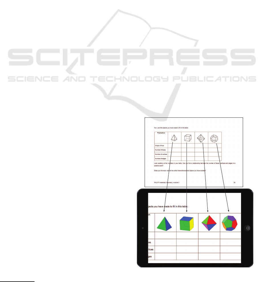
In this mobile era, more and more people start
reading and learning on their mobile devices such as
tablet PCs and cell phones. Furthermore, the mobile
devices now have been powerful enough to render 3D
geometric objects in real time. Therefore, as illus-
trated in Figure 1, if we can restore the 3D structure of
those solid geometric objects from the corresponding
2D line drawing images, we can present the illustra-
tions of them in a 3D style on the mobile devices, and
thereby can significantly improve the users’ reading
and learning experience.
∗
Corresponding author. Telephone: +86 010 82529542 Fax:
+86 010 62754532
Figure 1: Illustration of the application of solid geometric
object reconstruction technology to mobile reading. The
solid objects from left to right are tetrahedron, cube, octa-
hedron and dodecahedron respectively.
391
Zheng J., Wang Y. and Tang Z..
Solid Geometric Object Reconstruction from Single Line Drawing Image.
DOI: 10.5220/0005261203910400
In Proceedings of the 10th International Conference on Computer Graphics Theory and Applications (GRAPP-2015), pages 391-400
ISBN: 978-989-758-087-1
Copyright
c
2015 SCITEPRESS (Science and Technology Publications, Lda.)

The human can easily obtain the 3D structural in-
formation of an object from a single 2D line drawing
image, but how to make a computer have the same
ability remains a challenging problem. Over decades,
a number of methods have been proposed to recon-
struct the 3D geometric objects from single line draw-
ings. However, to the best of our knowledge, all these
methods assume that the input is the perfect sketch of
the line drawings, that is, all the line segments and
their intersections are correctly obtained. Therefore,
in this perspective, these methods are not capable of
achieving the task addressed in this paper, which is
the solid geometric object reconstruction from sin-
gle line drawing image. The main reason is that, the
sketch automatically extracted from single line draw-
ing image may be inaccurate, due to the limitations of
the algorithms involved in the sketch extraction pro-
cess or the poor quality of the line drawing image.
Hence, we need to find a more robust reconstruction
method, which can handle incomplete or inaccurate
sketches.
The key contribution of our work is an algorithm
to reconstruct 3D geometric objects from single line
drawing images. Compared to the existing meth-
ods, the proposed method is able to handle inaccu-
rate sketches which are not demonstrated in any pre-
vious works. Based on this algorithm, we implement
a mobile application which allows the user to tap on
the line drawing images in the screen of the phone
or tablet, then it instantly reconstructs the geometric
object in the image, and draws the reconstructed 3D
object onto the screen. The user can interact with the
3D object by gestures including dragging and rotat-
ing, which is essential to improve the user experience
in reading such electronic materials.
The rest of this paper is organized as follows. The
related work is briefly reviewed in section 2. An
overview and some assumptions of our method are
provided in section 3. Section 4 mainly discusses the
sketch extraction process in our method. Section 5
describes the 3D model matching process. Section
6 presents the 3D reconstruction algorithm. Experi-
mental results are provided in section 7 and conclu-
sions are drawn in section 8.
2 RELATED WORK
In the past two decades, a lot of researchers made ef-
forts to resolve the single line drawing-based 3D re-
construction problem. These methods can be roughly
categorized into 3 types: the regularity-based meth-
ods, the deduction-based methods and the divide-and-
conquer-based methods.
Regularity-based methods use some geometric
rules as constraints to construct a cost function, and
then minimize this function to obtain the 3D ob-
ject. Conventional rules include: (1) the face pla-
narity rule: the coplanar vertices of the line draw-
ing should also be coplanar 3D points after recon-
struction (Leclerc and Fischler, 1992; Shpitalni and
Lipson, 1996; Liu and Lee, 2001; Liu et al., 2002;
Liu and Tang, 2005); (2) angularity rule: all the an-
gles at the vertices of a line drawing should be the
same (Marill, 1991; Brown and Wang, 1996; Shoji
et al., 2001). Besides the preceding two rules, Lip-
son and Shpitalni(Lipson and Shpitalni, 1996) pro-
pose another 10 rules, such as line parallelism, line
verticality, isometry and corner orthogonality, et al.
Since the dimension of the search space according to
this type of methods is very high, some works (Liu
et al., 2008; Tian et al., 2009) try to reduce the dimen-
sion of the search space to improve the computational
efficiency of these methods.
Deduction-based methods usually make stronger
assumptions over the 3D objects corresponding to the
input line drawings, e.g., the 3D object has cubic cor-
ners (Lee and Fang, 2011; Lee and Fang, 2012), or
a symmetric plane exists in the 3D object (Cordier
et al., 2013), and so on. Based on these assumptions,
the reconstruction result is obtained by a deduction
process.
The third type of methods adopt divide-and-
conquer strategy to reconstruct the complex line
drawings (Chen et al., 2007; Xue et al., 2010; Liu
et al., 2011; Zou et al., 2014b; Yang et al., 2013;
Zou et al., 2014a; Xue et al., 2012). These meth-
ods split the line drawing to a set of simpler parts.
In particular, the traditional regularity-based methods
are often used to reconstruct each part. Among these
methods, Xue et al. (Xue et al., 2012) propose a re-
fined divide-and-conquer-based method, in which an
example-based approach is used to reconstruct each
part of the complex line drawing.
Given the perfect sketch of the line drawingsas the
input, the above methods achieve good reconstruc-
tion results. However, none of them demonstrate their
abilities to handle inaccurate sketches. In this work,
we present a more robust method to solve the single
line drawing-based 3D reconstruction problem, which
can handle inaccurate sketches. It worths noting that
our method is example-based, the same as the Xue et
al (Xue et al., 2012)’s method (E3D). The main dif-
ferences between our method and E3D are twofold:
1. The E3D method can only take the sketch of a line
drawing as input, while our method directly takes line
drawing image as input; 2. The E3D method needs
complete input sketches without missing or erroneous
GRAPP2015-InternationalConferenceonComputerGraphicsTheoryandApplications
392
Sketch extraction
image
sketch graph
3D model selection
a
c
a
b
a
b
a
h
c
a
h
b
a
b
...
3D model database
A B
CD
P
E
(a) (b) (c)
3D reconstruction
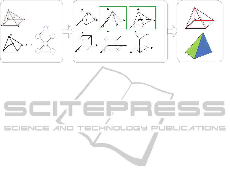
Figure 2: A brief illustration of our method. (a) Sketch extraction: the sketch is extracted by detecting the line segments and
intersections from the input line drawing image, and is represented by an undirected connected graph. (b) 3D model selection:
candidate 3D models (marked in green bounds) are selected from the 3D model database based on sub-graph isomorphism.
(c) 3D reconstruction: the reconstruction result is obtained by fitting the candidate models (red lines) to the sketch (black
lines). The reconstructed solid geometric object (a pyramid) is shown from another point of view.
edges, while our method does not need that. Although
the E3D method can handle more complex objects
based on a divide-and-conquer approach, it requires
the input to be a complete sketch of the line draw-
ing. Actually, all the experimental data shown in E3D
is man-made sketches created from a CAD software,
while our input data is the geometric images from the
PDF documents. Experimental results demonstrate
that our method is able to produce good results for
inaccurate sketches automatically extracted from the
input line drawing images.
3 OVERVIEW
Our method has three main steps. First, we extract
the lines from the image and convert them to an undi-
rected connected graph, which is called the sketch.
Note that due to the limitation of the sketch extrac-
tion algorithm, the extracted sketch is highly possible
to be inaccurate or even incomplete. Second, the ex-
tracted sketch is matched within a pre-built 3D model
database, producing some candidate models that are
analog to the sketch. Finally, an objective function
is constructed based on the coordinate residuals be-
tween the graph and the candidate models, and then
an optimal reconstruction solution is found based on
an optimization selection process. A brief illustration
of our algorithm is shown in Figure 2. It is worth
noting that, in this paper, we only consider the line
drawings solely consisting of straight line segments,
since most of the illustrations fall into this category.
The line drawings containing arcs will be considered
in our future work.
In order to clearly present our solution to the sin-
gle line drawing-base 3D reconstruction problem, we
first fix the related notations and definitions.
Definition 1. A 2D sketch is the graph representation
of the line drawing image, denoted by S = (x, G
s
),
where x = {x
1
, x
2
, . . . , x
n
} are the 2D coordinates of
the vertices, and G
s
is the undirected connected graph
indicating which two vertices are connected.
Definition 2. A 3D object is represented as an undi-
rected connected graph in 3D space, that is, O =
(X, G
o
), where X = {X
1
, X
2
, . . . , X
m
} are the 3D co-
ordinates of the vertices of the object, and G
o
is the
undirected connected graph indicating which two ver-
tices are connected.
Definition 3. A 3D model represents a kind of 3D ob-
ject controlled by a set of model parameters, which is
denoted by M = (A, X, G
m
), where A is the set of pa-
rameters, X is the set of vertices, and G
m
is the undi-
rected connected graph indicating which two vertices
are connected.
Definition 4. An instance of the 3D model is an 3D
object that is generated by the rotation and transla-
tion of the 3D model in 3D space.
4 SKETCH EXTRACTION
The input gray-scale image (the color image is first
converted to the gray-scale one) is scaled to a nor-
mal size(the longer edge is sized to 400 pixels and the
shorter edge is sized into corresponding proportion),
and then binarized with the OTSU method (Otsu,
1975), and then connected components of the fore-
ground pixels (the black pixels of the original input
image) are obtained.
SolidGeometricObjectReconstructionfromSingleLineDrawingImage
393
(a) (b) (c) (d)
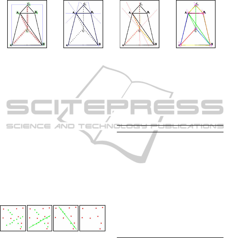
Figure 3: Illustration of sketch extraction. (a) connected component clustering. (b) solid line extraction. (c) dashed line
extraction. (d) generating the sketch (undirected connected graph).
4.1 Connected Component Clustering
As shown in Figure 3(a), there are usually 3 types of
the connected components according to their sizes:
the main body (the one bounded in blue rectangle),
the dashed line dots (the ones in red rectangles), and
the characters (the ones in green rectangles). Based
on these observations, We adopt the k-means (Harti-
gan and Wong, 1979) clustering (we set k=3 straight-
forwardly) algorithm to classify the types of the con-
nected components. The count of the foreground pix-
els, the height and width of the bounding box are
taken as the feature for clustering. After clustering,
we divide the connected components into 3 types:
the one whose bounding box is significantly larger
than the others is selected as the main body; the ones
with smallest bounding boxes and similar foreground
pixel counts are classified to the dashed line dots; the
remaining ones are then classified to the characters,
which are not involved in our further processing. This
strategy is simple yet effective to provide an estima-
tion of the component types.
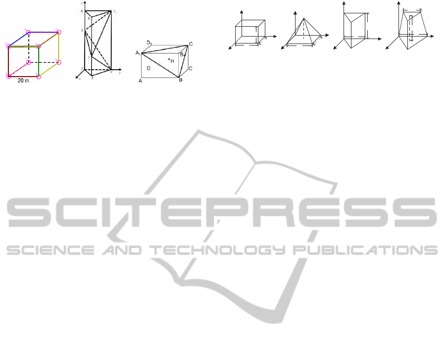
(a) (b) (c) (d)
Figure 4: The consensus-sampling extraction process (a)
the inliers and the outliers. (b)(c) lines extracted by
consensus-sampling of the inliers. (d) left outliers.
4.2 Line Extraction
We use the edge segment-based (Liu et al., 2014)
to extract the solid lines(Figure 3(b)), and propose
a sample-consensus-based algorithm (summarized in
algorithm 1) for dashed line extraction. The dashed
dots are first shrink to their center points as the input
of the algorithm. The dashed line extraction process
is illustrated in Figure 4. Figure 4(a) shows all the
input center points: the inliers are marked in green
color and the outliers are in red. Then two lines are
sequentially extracted by the sample-consensus pro-
cess in Figure 4(b) and 4(c), after which only outlier
points are left in Figure 4(d). This algorithm is effi-
cient and robust in presence of a few outliers. Figure
3(c) shows an example of the extracted dashed lines
from the line drawing image.
Algorithm 1: Dashed line extraction.
Input:
A set of central points V = {v
1
, v
2
, . . . , v
n
};
Output:
A set of lines L;
1: L = φ, G = φ;
2: For each pair of points v
i
, v
j
∈ V, calculate the
line l
ij
that goes through them, and find the inlier
points set P
ij
. Add P
ij
to G;
3: while G is not empty do
4: P := argmax|P
ij
|, i, j ∈ [1, n]. If |P| < 3 output
L and exit.
5: Calculate the line l by least-squares fitting of
the points in P.
6: Add l to set L. Remove P from G. Remove
all the points in P from the set V, and from all
existing P
ij
sets in G.
7: end while
8: Output L and stop.
4.3 Generating the Sketch
After the solid and dashed lines are extracted from the
input image, we further convert them into an undi-
rected connected graph. First, the intersection points
of the lines are determined, and the lines are cut into
line segments according to these intersection points.
Second, an image-based validation process is per-
formed to remove the false segments that only cover
very few foreground pixels. Third, the line segments
that are adjacent and collinear are merged to one seg-
GRAPP2015-InternationalConferenceonComputerGraphicsTheoryandApplications
394
(a) (b) (c)
Figure 5: 3 Types of unnecessary edges. (a) type 1. (b) type
2. (c) type 3.
ment. Finally, the vertices of the sketch graph are ob-
tained by merging the end points that are very close
to each other, and the edges of the sketch graph are
obtained according to the line segments. As shown in
Figure 3(d), the graph vertices are circled and labeled
by Arabic numbers, and the graph edges are drawn in
different colors.
4.4 Unnecessary Edges Removal
Some of the extracted line segments are correct ones,
but not useful or even harmful to the following recon-
struction process. In order to successfully reconstruct
the geometric object in the line drawing image, we
use some heuristics to remove some of the vertices
and edges from the obtained sketch graph as follows.
Type 1: Dangling Edges. In the extracted sketch
graph, a vertex point whose degree equals to 1 is
called a dangling point, and the corresponding edge
is called the dangling edge. For example, the edge
2-7
in Figure 5(a) is a dangling one.
Type 2: Docking Edges. We call a line segment as
“docking line segment” if one of its end points is at
the middle of another line segment. And the corre-
sponding edge is a docking edge. For example, in
Figure 5(b), the line segments CE, CF, C
1
E, and C
1
F
are docking ones.
Type 3: Diagonal Edges. The “diagonal line seg-
ment” is the one that connects the diagonal points of
a parallelogram in the sketch. And the corresponding
edge is a diagonal edge. As shown in Figure 5(c), the
line segments A
1
B, BC
1
, and A
1
C
1
are diagonal ones.
These unnecessary edges are excluded from the
reconstruction process introduced in the next section.
5 3D MODEL SELECTION
After obtaining the sketch graph of the line drawing,
we select some candidate 3D models with the similar
c
a
b
(a)
b
a
h
(b)
a
b
(c)
a
b
c
(d)
Figure 6: Examples of the 3D models. (a) cuboid. (b) pyra-
mid. (c) triangle-prism. (d) tetrahedron-frustum.
graph structure from the pre-built 3D model database.
The details will be introduced in the following sub-
sections.
5.1 3D Model Database
In this work, a 3D model is represented as an undi-
rected connected graph in the 3D space. Each vertex
of the model has a 3D coordinate X
i
, and the graph
is represented by G
m
. Moreover, a 3D model is con-
trolled by a number of model parameters (denoted as
set A), which represent the geometric attributes of the
3D model, such as width, height, depth. Some of
the examples are shown in Figure 6. Figure 6(a) is a
cuboid model. It has 3 parameters: A
cuboid
= {a, b, c},
where a, b, c are the width, height and length of the
cuboid model respectively. For a 3D model M, we
use a matrix which is composed by the elements of A
to represent the 3D coordinates of the vertices, which
is called the parametric matrix of the model and is de-
noted by V
M
. For example, the parametric matrix of
the cuboid is
V
cuboid
=
0 a a 0 0 a a 0
0 0 0 0 b b b b
0 0 c c 0 0 c c
, (1)
in which each column V
i
is the 3D Euclidean coordi-
nates of a vertex. Obviously, the parametric matrix
always has 3 rows and the number of columns equals
to the number of vertices.
We have totally defined 16 models to build the 3D
model database, which can cover almost all the cases
that appear in our experimental data set.
5.2 Matching the Sketch Graph within
the 3D Model Database
We select the candidate models from the 3D model
database based on sub-graph isomorphism. The sub-
graph isomorphism is a graph matching technique to
find a sub-graph in a given bigger graph G isomor-
phic to a given smaller graph H. We adopt the VF-
2(Cordella et al., 2004) algorithm to accomplish our
sub-graph isomorphism task.
We perform sub-graph isomorphism twice. In the
first time, we take the sketch graph G
s
as the bigger
SolidGeometricObjectReconstructionfromSingleLineDrawingImage
395

graph and the model graph G
m
as the smaller graph;
and in the second time, we conversely take G
m
, G
s
as
the bigger graph and the smaller graph respectively.
The first time of sub-graph isomorphism is per-
formed to handle the completely or over-completely
extracted sketches. For example, Figure 3(d) illus-
trates the extracted sketch from a line drawing im-
age of tetrahedron-frustum,in which the lines A
1
B and
A
1
C are not contained in the model of the tetrahedron-
frustum. We find the models whose number of ver-
tices are equal to or smaller than that of the sketch,
and are isomorphic to a sub-graph of the sketch. And
among these models, only the ones with the largest
number of vertices are selected as the candidate mod-
els. For the example shown in Figure 3(d), we first
find 4 models – pyramid, tetrahedron, triangle-prism
and tetrahedron-frustum, and finally select two mod-
els – the triangle-prism and the tetrahedron-frustum
as the candidate models, which are shown in Figure
6(c) and 6(d).
During the process of the sketch extraction, some
line segments may be not extracted or partially ex-
tracted, and thus the obtained sketch graph is usually
incomplete. In order to deal with these cases, we per-
form the second time of sub-graph isomorphism – fix
the 3D model G
m
as the bigger graph, and find sub-
graphs that are isomorphic to the sketch graph G
s
in it.
For example, Figure 5(a) shows an incomplete sketch
extracted from a line drawing image of the cuboid.
To be more specific, the two dashed lines (
4-7
and
6-7
) are completely missing. By applying the second
time of sub-graph isomorphism, the correct candidate
models (the cube and the cuboid et al) can still be se-
lected.
The models selected by the two times of sub-graph
isomorphism are all added to the list of candidate
models, which will be used in the 3D reconstruction
process.
6 3D RECONSTRUCTION
For each candidate 3D model, the reconstruction re-
sult is obtained by minimizing an objective function
of the residuals between the vertices of the sketch
and the 2D projections of the candidate model’s ver-
tices. And then, some bad reconstruction results are
rejected. Finally, the optimal result that best fits the
sketch is selected. The details of our reconstruc-
tion algorithm are introduced in the following sub-
sections.
6.1 Recovery of Each Candidate Model
After a sub-graph isomorphism, we obtain some cor-
respondence C = (X
C
, x
C
) between the subsets of the
vertices of the candidate model and the sketch graph,
where X
C
and x
C
are subsets of X and x respectively,
and C is a one-to-one correspondence relationship
between X
C
and x
C
. The coordinates of the subset
X
C
are X
C
= {X
i
1
, X
i
2
, . . . , X
i
C
}, where i
k
is the sub-
indices of X, and the coordinates of the subset x
C
are
x
C
= {x
j
1
, x
j
2
, . . . , x
j
C
}, where j
k
is the sub-indices of
x.
For each candidate model, the 3D reconstruction
process of our method aims to find an instance of it
whose 2D projection can best fit the sketch. To be
more specific, our target is to optimize an objective
function that minimizes the coordinate residuals be-
tween the matched vertices of the sketch and the can-
didate model. The objective function is the projection
error, which is given by
f =
n
C
∑
k=1
K(RV
i
k
+ t) − x
j
k
2
, (2)
where n
C
is the number of corresponding pairs of the
vertices; K =
1 0 0
0 1 0
is the parallel projection
matrix, R is the rotation matrix, t is the translation
vector, i
k
and j
k
are the indices of the corresponding
vertices of the sketch and the model, V
i
k
is the i
k
-th
column of the parametric matrix V, and x
j
k
is the 2D
coordinate of the j
k
-th vertex of the sketch. The opti-
mal solution is found by solving the following prob-
lem
˜
A,
˜
R,
˜
t = argmin
n
C
∑
k=1
K(RV
i
k
+ t) − x
j
k
2
subjectto :R
T
R = I,
(3)
where
˜
A is the optimal geometric parameters of the
model,
˜
R is the optimal rotation matrix, and
˜
t is the
optimal translation vector.
The objective function is a quadratic function with
an orthogonal constraint. We use the algorithm in
(Xue et al., 2012) to solve the problem in (3).
6.2 Optimal Reconstruction Result
Selection
For each candidate model, we obtain an reconstruc-
tion result by solving the objective function in (3).
We further select the best result among these recon-
struction results. The selection process is introduced
as follows.
First, the result with large projection error should
be rejected, that is, if the projection error f > δ, the
GRAPP2015-InternationalConferenceonComputerGraphicsTheoryandApplications
396

(a) (b) (c)
Figure 7: Example of pixel level validation. (a) a line draw-
ing image contains a tetrahedron. (b) tetrahedron model
with a missing line (red dashed line). (c) pyramid model
with missing lines.
result should be directly rejected, where δ is an em-
pirically set threshold (in this work, we set δ to 90.0).
Second, for the candidate models selected by the
second time of sub-graph isomorphism, there exists
some missing vertices and missing lines. For exam-
ple, in Figure 7(a) (the vertical line inside the tetra-
hedron has been removed as it’s a dangling line),
the dashed line of the tetrahedron is missing due to
failure of the sketch extraction step. Two candi-
date models are selected by the second time of sub-
graph isomorphism: the tetrahedron and the pyramid,
as shown in Figure 7(b) and 7(c) respectively. The
tetrahedron model’s missing line accurately overlaps
with the dashed line in the image, while the pyramid
model’s missing lines do not hit any line in the im-
age. Although the projection errors of the two mod-
els are exactly the same, we can select a better model
by the “pixel validation”: for each candidate model’s
reconstruction result, the “pixel vote” – the count of
the foreground pixels that the missing lines of the re-
constructed instance of the model pass through is col-
lected. We look for the pixels on both sides of the
missing lines at a small range, for tolerance of some
coordinate inaccuracies. If a candidate model’s pixel
vote is significantly smaller than the others, it should
be rejected.
Third, if two candidate models’ projection error
are nearly the same, we reject the one with a larger
parameter set A, since it’s a more complex model than
the other one. We want to select the model as simple
as possible, in order to solve the over-fit issue.
Finally, if there are still multiple candidate mod-
els, we choose the one with the smallest projection
error as the final selected model.
The optimal reconstruction algorithm is shown in
algorithm 2.
7 EXPERIMENT
We implement our algorithm in C++, and also de-
velop a graphical application both on PC and mobile
phone to demonstrate our method. As illustrated in
our demo, with this graphical application, user first
loads a PDF file and selects an rectangular area of 3D
geometry illustration from some pages; and after the
system processing, the reconstruction result is shown
in a pop up window. User can zoom and drag to rotate
the reconstructed object, as if it’s immersed in a 3D
space. No parameter setting is required for input; and
the whole process usually only takes 1-10 seconds.
Algorithm 2 : 3D reconstruction from extracted
sketch.
Input:
extracted sketch graph G
s
, candidate models
{M
k
};
Output:
the reconstructed 3D object;
1: For each candidate model M
k
, solve the mini-
mization problem in (3) by using algorithm in
(Xue et al., 2012). Let f
k
denote the projection
error, p
k
denotes the pixel vote, and A
k
denotes
the parameters set.
2: Find the candidate model with the highest pixel
vote. Let ˆp denote the highest pixel vote.
3: From the candidate models, remove the ones
whose f
k
> δ.
4: If one candidate model is generated by the second
time of sub-graph isomorphism, and its pixel vote
p
k
< 0.1∗ ˆp, remove it.
5: Keep the candidate models whose parameters set
A
k
has the smallest number of parameters, re-
move all the others.
6: If there are still more than one candidate models,
remove all except the one with the smallest pro-
jection error f
k
.
7: With the only one left model and it’s parameters,
Output RV + t as the final reconstructed 3D ob-
ject.
We collected over 40 PDF documents from the
internet (including books, papers, teaching materi-
als, slide shows and other types of documents), and
captured 303 line drawing images from them. Our
algorithm is tested over these line drawing images,
and some examples of the reconstruction results are
shown in Figure 8.
Evaluation. In the most related work of E3D (Xue
et al., 2012), the authors use the RMSA (root mean
squares of differences of angles) and the RMSE (root
mean squares of differences of Euclidean distances)
metrics to evaluate the reconstruction accuracy. How-
ever, we found these metrics not suitable for our case.
The reasons can be described as below. First, the line
drawings used in E3D are manually crafted in a CAD
SolidGeometricObjectReconstructionfromSingleLineDrawingImage
397
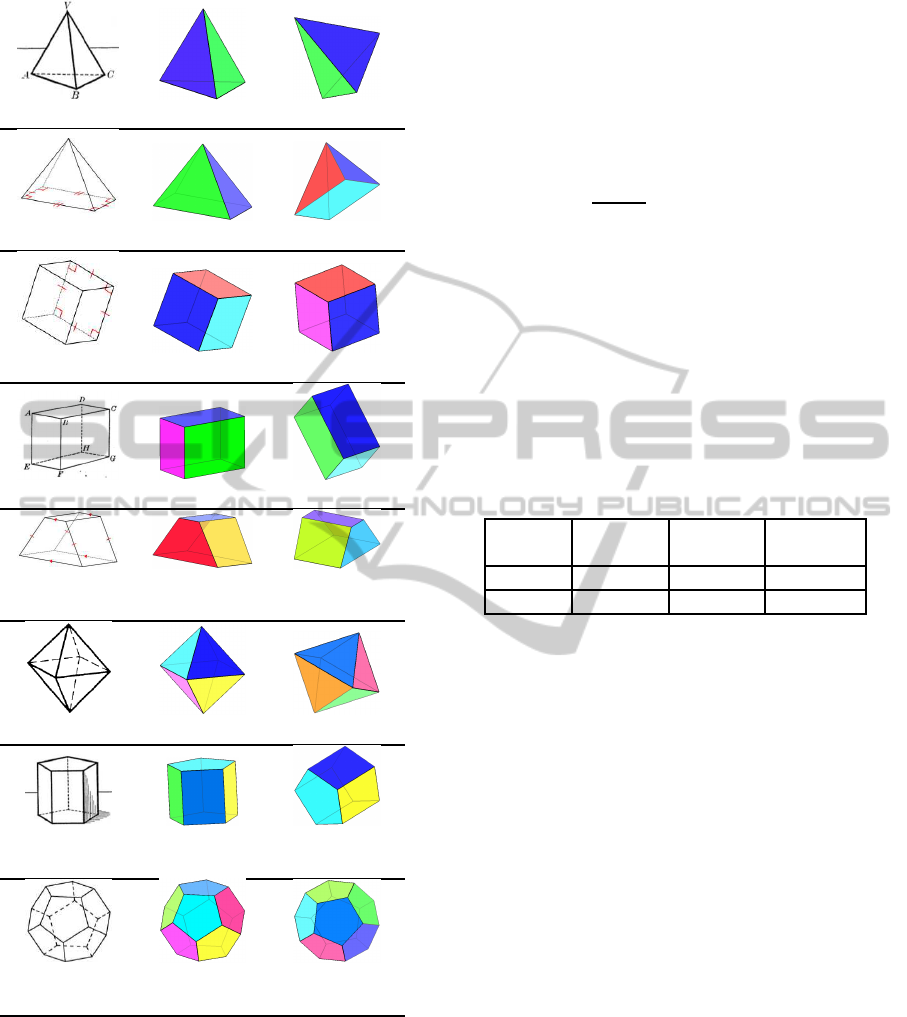
tetrahedron
pyramid
cube
cuboid
pyramid-
frustum
octahedron
pentagonal
prism
dodecahe-
dron
Figure 8: Examples of reconstruction results.The first col-
umn is the input line drawing image and the name of the
3D model. The second column is the reconstructed object
from original angle of view. The third column is the object
viewed from different angles.
software, so the ground truth is precisely known;
while our input data is just the line drawing image.
Second, for the applications such as mobile reading
and learning, users tend to care about whether the re-
construction result is the right 3D object illustrated
in the original line drawing image, rather than caring
about how close the reconstructed angles and points
are to the original line drawing. For these reasons,
we use a simple metric – the matching accuracy to
evaluate the proposed method and E3D. Let F denote
the test image set, and F
correct
denotes the set of cor-
rectly matched images, then the matching accuracy is
defined as f
a
=
|F
correct
|
|F|
.
Table 1 compares the results of our method and
E3D on our testing dataset. As we can see that
the matching accuracy of our method is significantly
higher than that of E3D. The reason why E3D per-
forms so poorly is that, as we have known, it can only
handle complete sketches while our method can also
handle incomplete or over-complete sketches. And in
our experiment, we find that, for most of the testing
line drawing images, the extracted sketch is inaccu-
rate (i.e., incomplete or over-complete). Therefore,
our method performs much better than E3D.
Table 1: Comparison between our method and E3D.
Method
Correct
match
Incorrect
match
Accuracy
E3D
42 261
13.9%
Ours
221 82
72.9%
We can also extend our method to the natural im-
ages as shown in Figure 9. Given an input image, we
first detect the straight lines in it as in Figure 9(b),
and then extract the sketch using the straight lines as
in Figure 9(c). Note that in this example, the extracted
sketch is incomplete, and the hidden side of the object
is invisible. Then the 3D geometric object in the im-
age is reconstructed. We paste the textures in the im-
age onto the faces of the box, as shown in Figure 9(d)
and Figure 9(e). The whole process is done automati-
cally, as opposed to the real image modeling example
shown in E3D. They need the user to manually sketch
along the edges of the object, and both the visible and
invisible edges must be drawn in the sketch.
Failure Analysis. Most failure cases happen when
there are both undetected and over-detected edges.
For example, the oblique-pyramid in Figure 10(a) is
mistakenly reconstructed as a tetrahedron in Figure
10(c). From the sketch in Figure 10(b), we can see
that the edge
CD
fails to be detected, and there are
some extra edges. Most extra edges like the axis and
the edge
AF
has been removed by the heuristics we
use, but the edge
AC
is not removed since the edge
CD
is not detected (thus the “diagonal heuristic” does not
apply). Finally, we end up getting only wrong candi-
date models from the first round of sub-graph isomor-
GRAPP2015-InternationalConferenceonComputerGraphicsTheoryandApplications
398
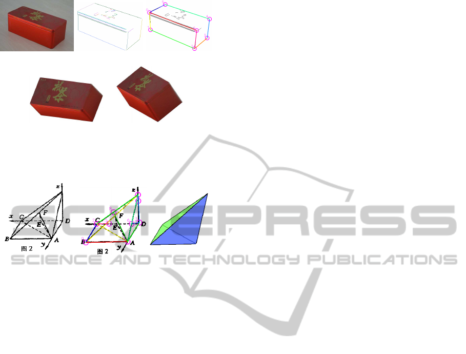
(a) (b) (c)
(d) (e)
Figure 9: Example of modeling from natural image. (a) an
input image. (b) straight lines detection. (c) sketch extrac-
tion. (d)(e) reconstructed 3D object in two different views.
(a) (b) (c)
Figure 10: An example of failure case. (a) input image. (b)
extracted sketch. (c) reconstruction result.
phism matching, and therefore it’s impossible to get
the correct reconstruction result.
Other failure cases include over-fitted model be-
ing taken, edges being too complicated to be recon-
structed, et al. But these are only occasional cases.
If we fine tune the algorithm to fit these occasional
cases, the whole matching accuracy would decline.
8 CONCLUSION AND FUTURE
WORKS
We have proposed a robust method to reconstruct
3D geometric object from single line drawing image.
Solid and dashed straight line segments are first ex-
tracted from the image and further represented as an
2D undirected connected graph, namely, the sketch.
Then, candidate models from a pre-built 3D model
database are selected through two rounds of sub-
graph isomorphism. Furthermore, for each candidate
model, reconstruction result is obtained by minimiz-
ing a cost function of residuals between the vertices of
the sketch and the 2D projections of the correspond-
ing vertices of the candidate model. Finally, some bad
reconstruction results are rejected and the optimal re-
sult that best fits the sketch is outputted. The pro-
posed method is tested on 303 line drawing images
and the experimental results demonstrate that: (1) it
can successfully reconstruct the solid geometric ob-
ject from single line drawing image; (2) it achieves
significantly higher matching accuracy than the state-
of-the-art method E3D. Our future works include: (1)
extracting line styles and labels to preserve the style
of the input; (2) reconstruction of the curved objects,
such as cylinders and spheres; (3) improving the re-
construction performance by taking syntax informa-
tion into account; (4) reconstruction of complex line
drawings, not limited to pre-built models in the model
database.
ACKNOWLEDGEMENTS
We’d like to thank all the reviewers for providing en-
couraging and valuable comments to our work. This
work is supported by National Natural Science Foun-
dation of China under Grant 61300061 and Beijing
Natural Science Foundation (4132033).
REFERENCES
Brown, E. and Wang, P. S. (1996). Three-dimensional ob-
ject recovery from two-dimensional images: a new ap-
proach. In Photonics East’96, pages 138–147. Inter-
national Society for Optics and Photonics.
Chen, Y., Liu, J., and Tang, X. (2007). A divide-and-
conquer approach to 3d object reconstruction from
line drawings. In Computer Vision, 2007. ICCV 2007.
IEEE 11th International Conference on, pages 1–8.
IEEE.
Cordella, L. P., Foggia, P., Sansone, C., and Vento, M.
(2004). A (sub) graph isomorphism algorithm for
matching large graphs. Pattern Analysis and Machine
Intelligence, IEEE Transactions on, 26(10):1367–
1372.
Cordier, F., Seo, H., Melkemi, M., and Sapidis, N. S.
(2013). Inferring mirror symmetric 3d shapes from
sketches. Computer-Aided Design, 45(2):301–311.
Hartigan, J. A. and Wong, M. A. (1979). Algorithm as 136:
A k-means clustering algorithm. Applied statistics,
pages 100–108.
Leclerc, Y. G. and Fischler, M. A. (1992). An optimization-
based approach to the interpretation of single line
drawings as 3d wire frames. International Journal of
Computer Vision, 9(2):113–136.
Lee, Y. T. and Fang, F. (2011). 3d reconstruction of poly-
hedral objects from single parallel projections using
cubic corner. Computer-Aided Design, 43(8):1025–
1034.
Lee, Y. T. and Fang, F. (2012). A new hybrid method
for 3d object recovery from 2d drawings and its
validation against the cubic corner method and the
optimisation-based method. Computer-Aided Design,
44(11):1090–1102.
SolidGeometricObjectReconstructionfromSingleLineDrawingImage
399

Lipson, H. and Shpitalni, M. (1996). Optimization-based
reconstruction of a 3d object from a single freehand
line drawing. Computer-Aided Design, 28(8):651–
663.
Liu, D., Wang, Y., Tang, Z., Li, L., and Gao, L. (2014).
Automatic comic page image understanding based on
edge segment analysis. In Proc. SPIE 9021, Docu-
ment Recognition and Retrieval XXI, pages 90210J–
90210J–12.
Liu, J., Cao, L., Li, Z., and Tang, X. (2008). Plane-based
optimization for 3d object reconstruction from single
line drawings. Pattern Analysis and Machine Intelli-
gence, IEEE Transactions on, 30(2):315–327.
Liu, J., Chen, Y., and Tang, X. (2011). Decomposition of
complex line drawings with hidden lines for 3d planar-
faced manifold object reconstruction. Pattern Analy-
sis and Machine Intelligence, IEEE Transactions on,
33(1):3–15.
Liu, J. and Lee, Y. T. (2001). Graph-based method for
face identification from a single 2d line drawing. Pat-
tern Analysis and Machine Intelligence, IEEE Trans-
actions on, 23(10):1106–1119.
Liu, J., Lee, Y. T., and Cham, W.-K. (2002). Identifying
faces in a 2d line drawing representing a manifold ob-
ject. Pattern Analysis and Machine Intelligence, IEEE
Transactions on, 24(12):1579–1593.
Liu, J. and Tang, X. (2005). Evolutionary search for faces
from line drawings. Pattern Analysis and Machine In-
telligence, IEEE Transactions on, 27(6):861–872.
Marill, T. (1991). Emulating the human interpretation of
line-drawings as three-dimensional objects. Interna-
tional Journal of Computer Vision, 6(2):147–161.
Otsu, N. (1975). A threshold selection method from gray-
level histograms. Automatica, 11(285-296):23–27.
Shoji, K., Kato, K., and Toyama, F. (2001). 3-d interpre-
tation of single line drawings based on entropy min-
imization principle. In Computer Vision and Pat-
tern Recognition, 2001. CVPR 2001. Proceedings of
the 2001 IEEE Computer Society Conference on, vol-
ume 2, pages II–90. IEEE.
Shpitalni, M. and Lipson, H. (1996). Identification of faces
in a 2d line drawing projection of a wireframe ob-
ject. Pattern Analysis and Machine Intelligence, IEEE
Transactions on, 18(10):1000–1012.
Tian, C., Masry, M., and Lipson, H. (2009). Physical
sketching: Reconstruction and analysis of 3d objects
from freehand sketches. Computer-Aided Design,
41(3):147–158.
Xue, T., Liu, J., and Tang, X. (2010). Object cut: Com-
plex 3d object reconstruction through line drawing
separation. In Computer Vision and Pattern Recogni-
tion (CVPR), 2010 IEEE Conference on, pages 1149–
1156. IEEE.
Xue, T., Liu, J., and Tang, X. (2012). Example-based 3d ob-
ject reconstruction from line drawings. In Computer
Vision and Pattern Recognition (CVPR), 2012 IEEE
Conference on, pages 302–309. IEEE.
Yang, L., Liu, J., and Tang, X. (2013). Complex 3d general
object reconstruction from line drawings. In Com-
puter Vision (ICCV), 2013 IEEE International Con-
ference on, pages 1433–1440.
Zou, C., Chen, S., Fu, H., and Liu, J. (2014a). Progres-
sive 3d reconstruction of planar-faced manifold ob-
jects with drf-based line drawing decomposition. Vi-
sualization and Computer Graphics, IEEE Transac-
tions on, PP(99):1–1.
Zou, C., Yang, H., and Liu, J. (2014b). Separation of line
drawings based on split faces for 3d object reconstruc-
tion. In Computer Vision and Pattern Recognition
(CVPR), 2014 IEEE Conference on, pages 692–699.
GRAPP2015-InternationalConferenceonComputerGraphicsTheoryandApplications
400
