
Illumination Model for Two-layer Thin Film Structures
Fukun Wu
1,2
and Changwen Zheng
1
1
Science and Technology on Integrated Information System Laboratory, Institute of Software,
Chinese Academy of Sciences, Beijing, China
2
University of Chinese Academy of Sciences, Beijing, China
Keywords:
Interference Effects, Multilayer Film Interference Method, Fresnel Coefficients, Microfacet Factor.
Abstract:
To address the problem of visualizing the interference effects of objects with multilayer film structures such
as soap bubbles, optical lenses and Morpho butterflies in the physics-based framework, a novel full-spectrum
multilayer film interference method is presented. This method applies the multi-beam interference equation
to effectively simulate the multiple reflection and transmission inside films, and calculate the composite re-
flectance and transmittance to model the amplitude and phase variations related to interference. The Fresnel
coefficients used for metallic and dielectric films are introduced to explain the absorption of photons due to the
film materials, and the microfacet scattering factor is also applied to simulate the complex optical effects such
as the isotropic and anisotropic phenomena caused by the roughness of the surface geometry. This method
is integrated into the existing ray tracer to further enhance the photorealistically rendering capabilities. The
experimental results demonstrate that our method can efficiently model the phase and amplitude information
of wave to generate high-quality realistic interference effects.
1 INTRODUCTION
Photorealistic rendering is the main rendering tech-
nology of the existing modeling softwares such as
Maya, 3Dmax and Blender. Different from the non-
photorealistic rendering technology, it is involved in
the physical simulation of interaction between light
and objects where the illumination information can
be accurately modeled. The ray tracing is generally
used for modeling the propagation process of light
in space. Specially, it calculate the reflectivity and
transmissivity from surfaces by acquiring the material
properties of objects, and eventually obtains the radi-
ant energy of each ray arriving at the imaging plane
after recursively tracing rays to generate the realistic
images.
The thin film interference is an important part
of photorealistically rendering. However, the exist-
ing graphical development platform or softwares lack
the ability of describing the phase of light. To con-
struct precise interference model to model the inter-
action between light and multilayer film structures in
order to visualize iridescent colors of objects coated
with multilayer films such as soap bubble, beetles
and butterflies is a significant but challengingresearch
task. In computer graphics, many wave models have
been developed to render the wave phenomena gen-
erated by these multilayer film structures. Gondek
et al. (Gondek et al., 1994), for example, used a
wavelength-dependent bidirectional reflectance dis-
tribution function and a virtual goniospectrophotome-
ter to analyze and generate the reflection spectrum of
thin films and pearl materials. Hirayama et al. (Hi-
rayama et al., 1999; Hirayama et al., 2000) con-
structed a series of multilayer dielectric and metallic
film models to visualize the richer interference effects
through the iterative calculation of multi-beam reflec-
tion and transmission. Sun (Sun, 2006) applied the
analytical calculation and the numerical simulation
methods to implement an iridescent shading process
to render the biological iridescences. These method
can approximately describe the wave properties of
films, but rarely consider the microstructure or ma-
terial characteristics of surfaces, which not applicable
for the accurate simulation of the anisotropic irides-
cent colors.
For the sake of accurately rendering the optical
phenomena of diverse film materials, this paper con-
structs a general multilayer film interference shader
in the ray-based framework. It adopts the multi-beam
interference equation and Fresnel formulae to account
for the multiple reflection, interference and absorp-
tion of light. Fresnel coefficients for dielectric and
metallic films are introduced to visualize interference
199
Wu F. and Zheng C..
Illumination Model for Two-layer Thin Film Structures.
DOI: 10.5220/0005261401990206
In Proceedings of the 10th International Conference on Computer Graphics Theory and Applications (GRAPP-2015), pages 199-206
ISBN: 978-989-758-087-1
Copyright
c
2015 SCITEPRESS (Science and Technology Publications, Lda.)

due to the complex refractive indexes.In addition, the
irregularity of multilayer film microstructures is in-
corporated into the iridescent illumination model to
accurately describe the isotropic and anisotropic opti-
cal properties. The new wave bidirectional scattering
distribution function is proposed and integrated into
the PBRT (Pharr and Humphreys, 2010) in the form
of the material plugin, which has become a practical
technology by applying the existing modeling soft-
ware to render complex interference optical effects.
2 RELATED WORK
In computer graphics, to solve the problem of wave
rendering in the physics-based rendering framework,
multiple classical technologies have been developed
where the wave scattering model is applied to sim-
ulate the behavior of light on surfaces (Smits and
Meyer, 1990; Dias, 1991; Gondek et al., 1994; Callet,
1996; Dumazet and Callet, 2009; Jakob et al., 2014).
For instance, Moravec(Moravec, 1981) used the wave
theory of light to solve the global illumination prob-
lem and applied wave model to computer graphics
based on the phase tracking technology. Kajiya (Ka-
jiya, 1986) developed a bidirectional reflectance dis-
tribution function to model the anisotropic spectral re-
flectance by numerically calculating Kirchhoff inte-
gral. Later, Stam (Stam, 1999) implemented a gen-
eral diffraction shaders, followed by the works of
Agu (Agu, 2002), Sun (Sun et al., 2000) and Wu (Wu
and Zheng, 2013), to render iridescent colors from
periodic structures such as compact discs in a ray-
based renderer. The solutions above, however, are
constructed to model diffraction effects that are a part
of wave rendering, not applicable for rendering film
interference effects due to the lack of ability of en-
capsulating phase variations into transmitted radiant
energy.
To construct the accurate interference model to
model the interactive behavior of light and surfaces
in order to visualize the iridescent appearance of ob-
jects coated with multilayer films such as soap bubble,
beetles and butterflies has attracted a lot of attentions.
There exist many models used for rendering these
interference effects generated by multilayer films.
Icart et al. (Icart and Arqu`es, 2000), for example,
constructed a physics-based bidirectional reflectance
model for multilayer systems consisting of homoge-
neous and isotropic thin films with rough boundaries,
which can account for interference, diffraction and
polarization effects. Hirayama et al. (Hirayama et al.,
1999; Hirayama et al., 2000; Hirayama et al., 2001)
constructed a comprehensive multilayer film inter-
ference model to model scattering characteristics of
rough multilayer surfaces. Sun (Sun, 2006) imple-
mented an iridescent shading process for rendering
the biological iridescences of butterflies and beetles
due to multilayer interference based on analytical cal-
culation and numerical simulation. Few of the previ-
ous models, however, takes into account specific ge-
ometrical properties of multilayer films or other sub-
wavelength microstructures. They also lack the abil-
ity of modeling the back-scattering and anisotropic
properties for photorealistic renderings of Morpho
butterfly. Okada et al. (Okada et al., 2013) applied the
nonstandard finite-difference time-domain method to
numerically solve Maxwell’s equations for brilliant
iridescences. This approach can gain accurate results,
but depends on a fine defined numerical grid. Hill et
al. (Hill et al., 2014) made a comprehensive descrip-
tion of physically based shading approaches which is
used as the basis of our proposed model.
3 IRIDESCENT ILLUMINATION
MODEL
The key to rendering iridescent colors of multilayer
films in the ray-based framework is to account for the
interaction between the films with the periodic struc-
ture and light with amplitude and phase. Therefore,
this paper builds on the multilayer film interference
theory and incorporates the geometry of rough sur-
faces to construct an accurate film interference shader
in order to model isotropic and anisotropic iridescent
effects, which is further integrated in Maya model-
ing software to improve its practicality. The irides-
cent colors from objects coated with similar multi-
layer films can be efficiently visualized where the re-
fractive indexes, thicknesses and amount of alterna-
tive arrangement of films and the incident direction of
light source play an important role.
3.1 Multi-beam Interference
When light interacts with multilayer films, it under-
goes multiple reflection, transmission and absorption
inside films. It is desired to develop a more general
model that take complex interactions into considera-
tion. In this work, we analytically compute multilayer
film interference based on the recursive composition
method (Hirayama et al., 1999; Sun, 2006) to visual-
ize optical properties of multilayer structures.
As an example, consider a pair of film and air lay-
ers as shown in Figure 1. Given a thickness H and
a refractive index n
j
, j = 0, 1, 2. The r
1
, r
2
, t
1
and
t
2
denote the reflection and transmission coefficients
GRAPP2015-InternationalConferenceonComputerGraphicsTheoryandApplications
200
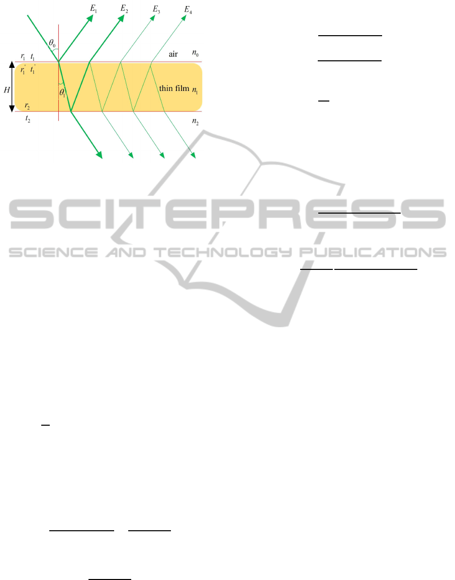
Figure 1: Interference modeling from a single layer film
structure of ridge.
of light propagating from air to film, and the r
′
1
and
t
′
1
denote the reflection and transmission coefficients
of light propagating from film to air, which are de-
rived using the Fresnel equations. The refractive an-
gle complies with Snell’s law. The indices of refrac-
tion of the air and the film are denoted as n
0
and n
1
respectively where n
0
= n
2
.
Hence the reflectivity of light from a pair of film
and air layers corresponding to Figure 1 are formu-
lated as
E
(r)
1
= r
1
E
(r)
0
E
(r)
2
= t
1
r
2
t
′
1
E
(r)
0
e
iδ
E
(r)
3
= t
1
r
2
(r
′
1
r
2
)t
′
1
E
(r)
0
e
i2δ
E
(r)
4
= t
1
r
2
(r
′
1
r
2
)
2
t
′
1
E
(r)
0
e
i3δ
.
.
.
(1)
where δ =
4π
λ
n
1
Hcosθ
1
denotes the phase difference
of two adjacent reflected or transmitted light propa-
gating through the film.
Referring to the interference theory of multilayer
films (Born and Wolf, 2005; Goodman, 2005; Liang,
2008; Hirayama et al., 1999), the composite reflectiv-
ity ¯r and transmissivity
¯
t of this single layer film can
be further formulated as
¯r =
E
(r)
1
+ E
(r)
2
+ · ··
E
(r)
0
≈
r
1
+ r
2
e
iδ
1+ r
1
r
2
e
iδ
(2)
Similarly, the transmitted coefficient is given by
¯
t ≈
t
1
+ t
2
1+ r
1
r
2
e
iδ
(3)
For two or more M-layer thin film system, we can
iterative the calculation of the reflection and transmis-
sion coefficients from the last layer adjacent to the
substrate to the first layer. For the Mth layer, for
instance,
¯r
M
=
r
M
+ r
M+1
e
iδ
M
1+ r
M
r
M+1
e
iδ
M
(4)
¯
t
M
=
t
M
t
M+1
1+ r
M
r
M+1
e
iδ
M
(5)
where δ is defined as
δ
M
=
4π
λ
n
M
H
M
cosθ
M
(6)
The calculation process is repeated until the first
layer adjacent to air. Finally, we can obtain the com-
posite reflectivity and transmissivity coefficients of
the multilayer film system.
Taking the above single layer film for example and
ignoring the polarization of the light, we can get the
reflectance distribution function of the film, namely,
R
fresnel
=
r
2
1
+ r
2
2
+ 2r
1
r
2
cosδ
1+ r
2
1
r
2
2
+ 2r
1
r
2
cosδ
(7)
The transmittance distribution derivation of the film is
written as
T
fresnel
=
n
2
cosθ
1
n
0
cosθ
0
t
2
1
t
2
2
1+ r
2
1
r
2
2
+ 2r
1
r
2
cosδ
(8)
The thin film interference is one of most simple
structural colors and widely exists in nature. Its most
remarkable characteristics is that the reflected wave
is selective. Namely, a specific wavelength plays a
determinant role in a specific direction. Based on the
Equation 7, the construction interference condition of
reflected wave is given by
2n
1
Hcosθ
1
= mλ (9)
Referring to the above constructive equation, it is
clear that the wavelength leading to higher reflectiv-
ity changes to a shorter wavelength with the increase
of the incident angle. The result is that the color
changes with viewing angle. For example, the color
of Morpho butterflies changes from blue to purple as
the viewing angle is increased that will be verified in
the following experiment.
3.2 Fresnel Coefficient
According to the above section, the composite re-
flection and transmission coefficients on film surfaces
play a key role in producing iridescent colors. They
affect the spatial distribution of radiant energy by
changing the amplitude and phase of light, which are
determined by Fresnel equation 10. In experiments,
light is assumed to be unpolarized and randomly ori-
ented. Hence, the reflectance of multilayer film struc-
ture is approximated as the average of squares of the
parallel and perpendicular polarization Fresnel terms.
IlluminationModelforTwo-layerThinFilmStructures
201
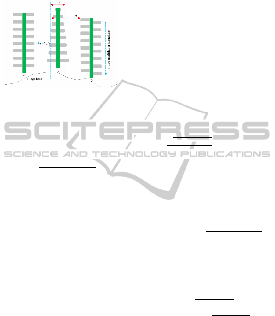
Figure 2: The approximated geometry of ridge films where
the film width b is set to 300 nm and the film separation d
is set to 675 nm based on the measurements of Platter (Plat-
tner, 2004).
r
||
j
=
n
j
cosθ
j−1
− n
j−1
cosθ
j
n
j
cosθ
j−1
+ n
j−1
cosθ
j
t
||
j
=
2n
j−1
cosθ
j−1
n
j−1
cosθ
j
+ n
j
cosθ
j−1
r
⊥
j
=
n
j−1
cosθ
j−1
− n
j
cosθ
j
n
j−1
cosθ
j−1
+ n
j
cosθ
j
t
⊥
j
=
2n
j−1
cosθ
j−1
n
j
cosθ
j
+ n
j−1
cosθ
j−1
(10)
where r
k
and r
⊥
denote the Fresnel coefficients for
parallel polarized light, t
k
and r
⊥
denote the coef-
ficients for perpendicular polarized light, and n
j−1
and n
j
denote the refractive indexes of incident and
transmitted medium respectively. The transmitted an-
gle complies with Snell’s law (Hirayama et al., 1999;
Pharr and Humphreys, 2010).
The applied Fresnel term, namely Equation 10,
depends on the assumption that the potential polar-
ization states of the light are not considered. This is
an approximation, as the reflected parallel term can
lead to a phase shift, or, in the case of total reflection,
become purely imaginary, therefore leading again to
a phase delay. On the other hand, the perpendicular
Fresnel term does not affect the phase. These situ-
ations, which may be important for interference, are
neglected by averaging them.
3.3 Regularity and Irregularity of
Structures
For the multilayer film structures with a certain
amount of irregularity such as Morpho butterflies,
the occlusion, shadowing and interreflection of light
among ridges may lead to the uneven spatial distribu-
tion of energy as illustrated in Figure 2. For example,
Kinoshita and Yoshioka (Kinoshita et al., 2002; Ki-
noshita and Yoshioka, 2005) have demonstrated that
the behavior of light is the result of joint action of
the regularity and irregularity of multilayer film struc-
tures.
It is necessary to incorporate the irregularity of
the film structure to model the diffusive nature where
isotropic Phong exponent (Phong, 1975) is commonly
used (Sun, 2006). However, some film structures of-
ten show backscattering and anisotropic spectral char-
acteristics. Many geometrical models have been de-
veloped (Torrance and Sparrow, 1967; Blinn, 1977;
Wu et al., 2010). They work by statistically model-
ing the scattering of light, where the wave-likeproper-
ties are ignored. As an extension, we incorporate the
Ashikhmin microfacet scattering shader (Ashikhmin
and Shirley, 2000), namely Equation 11, into the
wave BSDF illumination model to describe the local
anisotropic effects.
D
facet
=
p
(e
x
+ 2)(e
y
+ 2)
2π
(ω
h
· n)
e
x
cos
2
φ+e
y
sin
2
φ
(11)
where ω
h
denotes the half angle vector for incident
direction ω
i
and outgoing direction ω
o
, n denotes the
surface normal, φ denotes the orientation angle, and
e
x
and e
y
denote the exponents of anisotropic distri-
bution along the x and y axes respectively.
This paper develops a new wave bidirectional
scattering distribution function that provides an effi-
cient way in accurately rendering the interference ap-
pearance of films with periodic structures, written as
BSDF
λ
= c
a
I
dif fuse
+ c
b
D
facet
F
fresnel
G(ω
o
, ω
i
)
4cosθ
o
cosθ
i
(12)
where I
dif fuse
denotes the diffuse effects due to the
surface irregularities, F
fresnel
is determined by Equa-
tions 7 and 8, and c
a
and c
b
is the weighted coef-
ficient. A geometric attenuation term G(ω
o
, ω
i
) is
defined as (Torrance and Sparrow, 1967; Pharr and
Humphreys, 2010)
G(ω
o
, ω
i
) = min(1,
2(n· ω
h
)(n· ω
o
)
ω
o
· ω
h
,
2(n· ω
h
)(n· ω
i
)
ω
o
· ω
h
) (13)
where ω
h
denotes the bisector of ω
i
and ω
o
, and n is
the the surface normal.
4 SIMULATIONS
We implemented our wave model for rendering iri-
descent colors of objects coated with multilayer thin
GRAPP2015-InternationalConferenceonComputerGraphicsTheoryandApplications
202
films by creating a new material plugin for the PBRT
system (Pharr and Humphreys, 2010). All of the im-
ages in this work were produced using Maya software
on a Dell T7600 workstation with a 2.40 GHz Intel
Xeon CPU E5-2609 and a NVIDIA Quadro 6000. We
focused on the visible spectrum (350∼750 nm) and
showed physics-based renderings as interference ex-
amples for the multilayer structures.
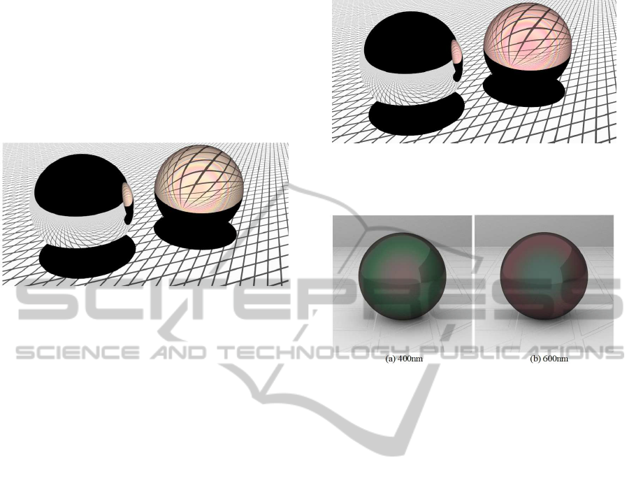
Figure 3: Renderings from a mirror sphere with perfect
specular reflection (left) and a glass sphere coated with the
420 nm dielectric film (right).
Figure 3 visualizes the optical phenomena of a
single layer dielectric film coating on a glass sphere
due to the multi-beam interference where refractive
indices of the glass and dielectric materials are set to
1.5 and 2.0 respectively. Note how refraction through
the transmissive object distorts the scene behind it and
how the left mirror reflects the interference effect.
In Figure 4, our model is further applied to render
the iridescent patterns of objects coated with a 450
nm dielectric film, whose interference effects clearly
appear on the near mirror surface. The indices of re-
fraction of substrate and dielectric are set to 1.5 and
2.0. Compared with Figure 3, the color shows a shift
to red with the increase of the film thickness which is
in agreement with the experiments.
This paper also implements the film interference
patterns of opaque objects as illustrated in Figure 5
where Blinn (Blinn, 1977) isotropic exponent is used.
The indices of refraction of substrate and dielectric
are also set to 1.5 and 2.0. In addition, the approach
proposed in this article is applicable for other cases
of iridescence rendering. For example, Figures 6
and 7 are two examples of anisotropic renderings of
opaque objects based on the proposed approach in the
physics-based PBRT (Pharr and Humphreys, 2010),
where the parameters denoting the film thickness and
the microfacet roughness used for each object can be
easily adjusted as needed. We addressed the effects
of the surface roughness and anisotropy on the visual
optical appearance where Ashikhmin (Ashikhmin and
Shirley, 2000) anisotropic functions is used as the ba-
sis.
The iridescent objects can be biological or nonbio-
Figure 4: Renderings from a mirror sphere coated with per-
fect specular reflection (left) and a glass sphere with the 450
nm dielectric film (right).
Figure 5: Interference renderings of opaque objects coated
with 400 nm and 600 nm dielectric films respectively.
logical. With the help of the optics and electric micro-
scopes, researchers have extensively reported the tree-
like periodic structures of ridges on Morpho butterfly
wings as shown in Figure 2 where ridges consist of al-
ternate cuticle film and air. Our proposed model can
be used for generate iridescent colors of butterflies as
illustrated in Figure 8. The four butterflies with differ-
ent structural parameter values are rendered , where
the thickness of film layer is set to 80 nm, 100 nm,
120 nm, and 135 nm respectively. From left to right,
the rendered colors of wings are approximate violet,
blue, yellow and red. Comparing these cases, a color
shift from the violet to the red happens. A detailed
comparison with the work of Sun (Sun, 2006) is fur-
ther illustrated in Figure 9. This renderings also agree
with the observed iridescences and experimental mea-
surements of Morpho butterflies (Fox, 1976; Simon,
1971; Vukusic et al., 1999). This experimental mea-
surements provide us with a basis to apply the mul-
tilayer interference model to visualize the iridescent
colors reflected by the biological structures.
5 CONCLUSION AND FUTURE
WORK
In the photorealistic rendering field, a lot
of attentions are paid to the wave properties of
IlluminationModelforTwo-layerThinFilmStructures
203
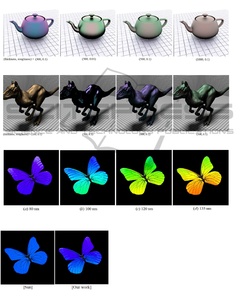
Figure 6: Interference renderings of teapots with the different surface roughnesses and thin film thicknesses.
Figure 7: Interference renderings of kangaroos with the different surface roughnesses and thin film thicknesses.
Figure 8: Rendered biological iridescences of Morpho butterflies consisting of tree-like ridge structures with cuticle films of
different thicknesses (left to right: 80 nm, 100 nm, 120 nm and 135 nm).
Figure 9: Comparison of rendered biological iridescences
of Morpho butterfly wings with 90nm cuticle layer thick-
ness using Sun butterfly shader (Sun, 2006) (left) and our
proposed multilayer interference model (right) respectively.
multilayer film structures. This paper constructs
an interference illumination model to visualize the
iridescent colors caused by the interaction of light
and layered structures where the indices of refraction,
thicknesses and the irregular geometry of films play
an important role. In ray tracers, This model creates
a wavelength-dependent bidirectional scattering
distribution function to describe the spatial spectrum
distribution of light. The multi-beam interference
equations have been introduced to represent the mul-
tiple reflection and transmission inside films in order
to realistically render local illumination. The Fresnel
formulae for dielectric and metallic films are also
described which are applied to trace the amplitude
and phase variations. In addition, the microfacet
scattering coefficient is incorporated to consider
GRAPP2015-InternationalConferenceonComputerGraphicsTheoryandApplications
204

the optical characteristics from rough surfaces for
the sake of accurately exhibiting backscattering and
anisotropic phenomena. Compared with experimen-
tal measurements, we have shown that this model
suffices to describe the optical effects, and have
facilitated its practical application in Maya software.
However, there still exist lots of work for future.
For example, how to handle the polarized effects of
light. Due to the complexity of film structures, it is
desirable to gain the measured appearance data to im-
prove accuracy of wave rendering. It may also be
necessary to consider the special anti-aliasing such
as spectral ray differential (Elek et al., 2014) in or-
der to addressing the issue of high frequencies in the
spectrum. In addition, our proposed model can be ap-
plied to render other objects exhibiting structural col-
ors such as optical lenses, beetles and birds.
ACKNOWLEDGEMENTS
We sincerely acknowledge all anonymous review-
ers for their valuable comments. This work was
funded by National High Technology Research and
Development Program of China (2012AA011206 and
2009AA01Z303).
REFERENCES
Agu, E. (2002). Diffraction shading models for iridescent
surfaces. In Proceedings of IASTED VIIP.
Ashikhmin, M. and Shirley, P. (2000). An anisotropic phong
brdf model. Journal of Graphics Tools, 5(2):25–32.
Blinn, J. (1977). Models of light reflection for computer
synthesized pictures. In Proceedings of SIGGRAPH
’77, pages 192–198.
Born, M. and Wolf, E. (2005). Principles of Op-
tics:Electromagnetic Theory of Propagation, Interfer-
ence and Diffraction of Light. Cambridge University
Press, 7th edition.
Callet, P. (1996). Pertinent data for modelling pigmented
materials in realistic rendering. Computer Graphics
Forum, 15(2):119–127.
Dias, M. (1991). Ray tracing interference color. IEEE Com-
puter Graphics and Applications, 11(2):54–60.
Dumazet, S. and Callet, P. (2009). Simulation of pearls,
physically based rendering, the virtuelium approach.
In AIC Congress, Sydney, Australia.
Elek, O., Bauszat, P., Ritschel, T., Magnor, M., and Sei-
del, H.-P. (2014). Spectral ray differentials. Computer
Graphics Forum (Proceedings of EGSR), 33(4).
Fox, D. (1976). Animal Biochromes and Structural colours.
University of California Press, Berkeley, CA.
Gondek, J., Meyer, G., and Newman, J. (1994). Wavelength
dependent reflectance functions. In Proceedings of
SIGGRAPH ’94, pages 213–219.
Goodman, J. (2005). Introduction to Fourier optics.
Roberts&Co., Englewood, Colo., 3rd edition.
Hill, S., McAuley, S., Dupuy, J., Gotanda, Y., Heitz, E.,
Hoffman, N., Lagarde, S., Langlands, A., Megibben,
I., Rayani, F., and de Rousiers, C. (2014). Physically
based shading in theory and practice. In ACM SIG-
GRAPH 2014 Courses, SIGGRAPH ’14, pages 23:1–
23:8, New York, NY, USA. ACM.
Hirayama, H., Kaneda, K., Yamashita, H., and Monden, Y.
(2001). An accurate illumination model for objects
coated with multilayer films. Computers & Graphics,
25(3):391–400.
Hirayama, H., Kaneda, K., Yamashita, H., Monden, Y., and
Yamaji, Y. (1999). Visualization of optical phenomena
caused by multilayer films with complex refractive in-
dices. In Proceedings of the 7th Pacific Conference on
Computer Graphics and Application, pages 128–137.
Hirayama, H., Yamaji, Y., Kaneda, K., Yamashita, H., and
Monden, Y. (2000). Rendering iridescent colors ap-
pearing on natural objects. In Proceedings of the 8th
Pacific Conference on Computer Graphics and Appli-
cation, pages 15–22.
Icart, I. and Arqu`es, D. (2000). A physically-based brdf
model for multilayer systems with uncorrelated rough
boundaries. In Rendering Techniques, pages 353–364.
Jakob, W., D’Eon, E., Jakob, O., and Marschner, S. (2014).
A comprehensive framework for rendering layered
materials. In Proceedings of SIGGRAPH ’14.
Kajiya, J. (1986). The rendering equations. In Proceedings
of SIGGRAPH ’86, volume 20, pages 143–150.
Kinoshita, S. and Yoshioka, S. (2005). Structural colors
in nature:the role of regularity and irregularity in the
structure. In ChemPhysChem, volume 6, pages 1442–
1459.
Kinoshita, S., Yoshioka, S., Fujii, Y., and Okamoto, N.
(2002). Photophysics of structural color in the mor-
pho butterflies. In Forma, volume 17, pages 103–121.
Liang, Q. (2008). Physical optics. Publishing House of
Electronics Industry, 3rd edition.
Moravec, H. (1981). 3d graphics and the wave theory. In
Proceedings of SIGGRAPH ’81, pages 289–296.
Okada, N., Zhu, D., Cai, D., Cole, J., Kambe, M., and
Kinoshita, S. (2013). Rendering morpho butterflies
based on high accuracy nano-optical simulation. Jour-
nal of Optics, 42(1):25–36.
Pharr, M. and Humphreys, G. (2010). Physically based ren-
dering: from theory to implementation. Morgan Kauf-
mann, 2nd edition.
Phong, B. (1975). Illumination for computer generated pic-
tures. Communications of the ACM, 18(6):311–317.
Plattner, L. (2004). Optical properties of the scales of mor-
pho rhetenor butterflies:theoretical and experimental
investigation of the back-scattering of light in the vis-
ible spectrum. Computer Graphics Forum, 1:49–59.
Simon, H. (1971). The Splendor of Iridescence of Structural
Colors in the Animal World. Dodd, Mead & Company,
New York, NY.
IlluminationModelforTwo-layerThinFilmStructures
205

Smits, B. and Meyer, G. (1990). Newton’s col-
ors:simulating interference phenomena in realistic im-
age synthesis. In Proceedings of Eurographics Work-
shop on Photosimulation, Realism and Physics in
Computer Graphics, pages 185–194.
Stam, J. (1999). Diffraction shaders. In Proceedings of
SIGGRAPH ’99, pages 101–110.
Sun, Y. (2006). Rendering biological iridescences with
rgb-based renderers. ACM Transactions on Graphics,
25(1):100–129.
Sun, Y., Fracchia, F., Drew, M., and Calvert, T. (2000). Ren-
dering iridescent colors of optical disks. In EGWR,
pages 341–352.
Torrance, K. and Sparrow, E. M. (1967). Theory of off-
specular reflection from roughened surfaces. Journal
of the Optical Society of America, 57(9):1105–1112.
Vukusic, P., Sambles, J., Lawrence, C., and Wootton, R.
(1999). Quantified interference and diffraction in
single morpho butterfly scales. In Proceedings of
the Royal Society B:Biological Sciences, volume 266,
pages 1403–1411.
Wu, F.-K. and Zheng, C.-W. (2013). A comprehensive
geometrical optics application for wave rendering.
Graphical Models, 75(6):318–327.
Wu, J.-Z., Zheng, C.-W., and Hu, X.-H. (2010). Realistic
rendering of bokeh effect based on optical aberrations.
The Visual Computer, 26:555–563.
GRAPP2015-InternationalConferenceonComputerGraphicsTheoryandApplications
206
