
A Combined Graph-based Approach for Systems Design And Verification
Najet Zoubeir and Adel Khalfallah
D
´
epartement du G
´
enie Logiciel et Syst
`
emes d’Information, Institut Sup
´
erieur d’Informatique, Ariana, Tunisia
Keywords:
Graph Transformation Systems, Software Architecture Analysis, Syntax, Semantics, Verification.
Abstract:
Software architecture’s interoperability faces many problems when it comes to integrating different compo-
nents or formalisms in describing the architecture. Even within the same modeling language such as UML, the
diversity of notations and the lack of semantic information make the interoperability between models difficult.
In this paper, we propose semantic foundations that unify the notations of classes, interactions and constraints,
and hence provide a robust basis for models interoperability. We rely on graphs and graph transformations to
describe systems structure and behavior, semantics and constraints in a combined form within an integrated
framework, which constitutes a robust basis for automated software architecture analysis.
1 INTRODUCTION
Describing the software architecture of a given sys-
tem is a challenging task, defined as ”the set of de-
sign decisions which, if made incorrectly, may cause
your project to be canceled” (E. Woods, 2010). Yet,
describing software architecture should not be a pur-
pose on itself. In fact, designers and architects, while
and after describing architecture, should be able to en-
hance their decisions by analyzing and optimizing the
architecture.
The Unified Modeling Language has known a
wide success in describing systems architecture, due
to the flexibility and universality of its graphical no-
tations. The diversity of notations in UML diagrams
enriches the architecture description, however, it cre-
ates distances between the diagrams, and hence, ob-
stacles for models interoperability. This lack of inter-
operability would make it difficult to analyze results
from different models.
Through our work, we try to enhance models in-
teroperability by unifying the notations describing
systems structure and behavior. We assume that the
semantic information is an essential factor for refin-
ing architecture analysis, as well as constraints veri-
fication. In this paper, we propose a framework for
software architecture description, verification and ex-
ecution using the unique notation of graphs and graph
transformations. Our proposed framework offers the
following features:
• Models syntax and semantics description: Both
syntactic and semantic information are necessary
for architecture analysis, such as for design pat-
terns or architectural styles recognition. In fact,
the more information the architecture provides,
the more correct and refined the patterns utiliza-
tion will be. This description is homogenous since
the syntax and semantics are described in a com-
bined form using the formalism of graphs;
• Constraints and properties expression and verifi-
cation on models: There are two levels of con-
straints on models: the meta-level constraints, re-
stricting the number of models satisfying a given
meta-model, and model-level constraints describ-
ing the model properties and constraints. A soft-
ware architecture description has to permit to ex-
press and verify the different levels of constraints,
allowing designers to analyze architecture, espe-
cially regarding quality. These constraints, from a
verification point of view, are a means of test case
generation, which creates with graphs an adjacent
state space permitting to search for states violat-
ing these constraints;
• Identify systems behavior: which permits to trace
the execution of the systems, and consequently
identify its desirable and undesirable behaviors.
The robust theoretical foundations of the formalism
of graphs permit to automate a set of analysis on the
created architectures, such as design optimization and
quality evaluation. Figure 1 resumes the features pro-
vided by our graph-based framework for software ar-
chitecture description: models structure and behav-
ior expression, model-level and meta-level constraints
346
Zoubeir N. and Khalfallah A..
A Combined Graph-based Approach for Systems Design And Verification.
DOI: 10.5220/0005272603460353
In Proceedings of the 3rd International Conference on Model-Driven Engineering and Software Development (MODELSWARD-2015), pages 346-353
ISBN: 978-989-758-083-3
Copyright
c
2015 SCITEPRESS (Science and Technology Publications, Lda.)
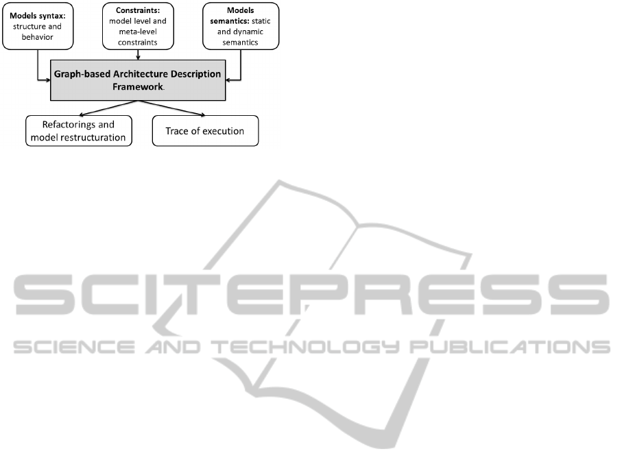
Figure 1: Architecture Description Framework Features.
definition and verification, and models static and dy-
namic semantics description. The framework has to
offer also the possibility to execute models and to
trace this execution.
2 RELATED WORK
Graph Transformation Systems (GTSs) are broadly
used in software engineering: models transformation,
tools implementation, testing (Chan et al., 2009), vi-
sual languages semantics description, etc. In this par-
ticular last area, diverse graph-based semantics de-
scription techniques have been proposed. Describ-
ing the semantics of UML diagrams belonging to dif-
ferent views has been the focus of many works, and
graph systems has known a wide success in this do-
main, due to the formal and universal nature of this
formalism. For example, graph-based semantics for
statechart diagrams were proposed in (Varro, 2002;
Engels et al., 2000; Gogolla and Presicce, 1998),
sequence diagrams in (Hausmann et al., 2004), ac-
tivity diagrams in (Hausmann, 2005) and class dia-
grams in (Gogolla and Richters, 1998). Integrated
semantics that combine subsets of UML diagrams
were proposed in diverse works, such as the works
in (Kuske et al., 2002; Gogolla et al., 2003) that
propose a graph-based integrated semantics for UML
class, object and statechart diagrams, and the work
in (Holscher et al., 2006) which considers a larger
subset of UML diagrams, including further the use
cases and interaction diagrams. Among these works,
the Dynamic Meta-Modeling approach (DMM) (En-
gels et al., 2000; Hausmann et al., 2004; Hausmann,
2005) proved to be valuable, since it does not target
a specific application purpose or specific notations of
UML, and focuses on the semantics definition on a
meta level. Although our work was inspired by some
of the DMM approach assets, such as dynamic se-
mantics definition and semantic mappings, it is distin-
guished by a more complete perspective of the archi-
tectural activity, which combines structure, behavior
and constraints.
Graph-based constraints semantics are proposed
in different works (Bauer, 2008; Rutle et al., 2012;
Dang and Gogolla, 2008; Rensink and Kleppe, 2008;
Bottoni et al., 2002; Winkelmann et al., 2008; Dang
et al., 2010). The work in (Bauer, 2008) treats
constraints as additional refinements of the match-
ing in Graph Transformation Rules (GTRs). Works
in (Rutle et al., 2012; Rensink and Kleppe, 2008)
manipulate OCL expressions whether in their textual
form (Rensink and Kleppe, 2008) or using First Or-
der Logic (Rutle et al., 2012), which are notations ex-
ternal to graphs, and hence the proposed semantics
are heterogeneous. Works in (Bottoni et al., 2002;
Winkelmann et al., 2008) propose graphical descrip-
tion for constraints using graph grammars (Winkel-
mann et al., 2008) and collaboration diagrams (Bot-
toni et al., 2002). In (Bottoni et al., 2002) the pro-
posed graph visualization for OCL constraints seman-
tics is quite complex, especially for advanced OCL
constraints. Besides, the transformation to graphs
uses a hybrid notation based on textual syntax. The
work in (Winkelmann et al., 2008) addresses a re-
stricted subset of OCL expressions, but does not study
the diverse placements of constraints. The works in
(Dang and Gogolla, 2008; Dang et al., 2010) com-
bine OCL in its textual form with Triple Graph Gram-
mars in order to check conformance between mod-
els. However, these multi-leveled and multi-viewed
graph-based semantics are proposed separately, i.e.
no combined graph-based semantics was proposed to
represent systems structure, behavior and constraints
through different modeling levels.
The approach proposed in this paper tries to take
full benefits of the formalism of graph systems, and
proposes a graph-based framework for software archi-
tecture description that integrates models structure,
dynamics and constraints within a unified formalism
that provides robust basis for exploiting models syn-
tactic and semantic information. We assume that our
framework will facilitate and automate a considerable
set of software architecture analysis.
The remainder of this paper is organized as fol-
lows: In section 3 we will highlight the importance
and the use of the semantic information in software
architecture analysis. In section 4 we will describe the
structure of our proposed framework by presenting a
set of architectural meta-models for systems syntax
and semantics. This section will also specify the se-
mantic mappings that will associate to every syntac-
tic and semantic element in a model, a corresponding
graph in a GTS. Section 5 will be devoted to intro-
duce our proposed graph-based verification. We will
present the meta-level constraints as a set of well-
ACombinedGraph-basedApproachforSystemsDesignAndVerification
347
formedness rules of the interactions semantics. In
this section, we will show the transformation of these
well-formedness rules to GTRs, and how they can be
checked on models. The last section will be devoted
to a conclusion and a presentation of our further work.
3 ARCHITECTURE ANALYSIS
AND SEMANTICS
In order to perform diverse analyses on software ar-
chitecture, all kinds of information are required. The
first kind is the syntactical information. Such infor-
mation constitutes the basic level of information pro-
vided by any architecture description language. The
second kind of information is the semantic one, which
may concern diverse aspects, such as model elements
semantics, operation semantics, constraints seman-
tics, etc.
Great amount of researches have been conducted
in the description and expression of systems seman-
tics. In this section, we will try to point out two
specific matters: How exactly semantic information
is useful in analyzing software architecture, and what
approaches of semantics permit to perform these anal-
yses. We consider the set of architecture analyses
we presented in the introduction: software architec-
ture optimization, quality evaluation and architecture
simulation. Semantic information can have a great
use in refining and optimizing software architecture.
In fact, architecture description that provides infor-
mation such as attributes values (in a denotational
way), methods operational semantics, interactions na-
ture (synchronous or asynchronous) and sequencing,
etc. can easily be implemented using a programming
language. Semantics also can be helpful in optimiz-
ing software architecture. In fact, through a previ-
ous work based on models syntax in order to charac-
terize systems architecture (Zoubeir and Khalfallah,
2010), we noticed that it was insufficient, especially
when it comes to behavior recognition or injection.
Adding semantic information such as the operational
semantics of methods, will definitely lead to better al-
gorithms for these tasks.
Semantic information is also needful for systems
simulation. In fact, in order to trace the execution of
a system it is necessary to identify its diverse possi-
ble behaviors. This task cannot be performed with-
out semantic information, and especially operational
semantics. The operational semantics approach is in-
deed particularly useful in performing this purpose,
since it interprets systems as state transition systems
(Plotkin, 1981).
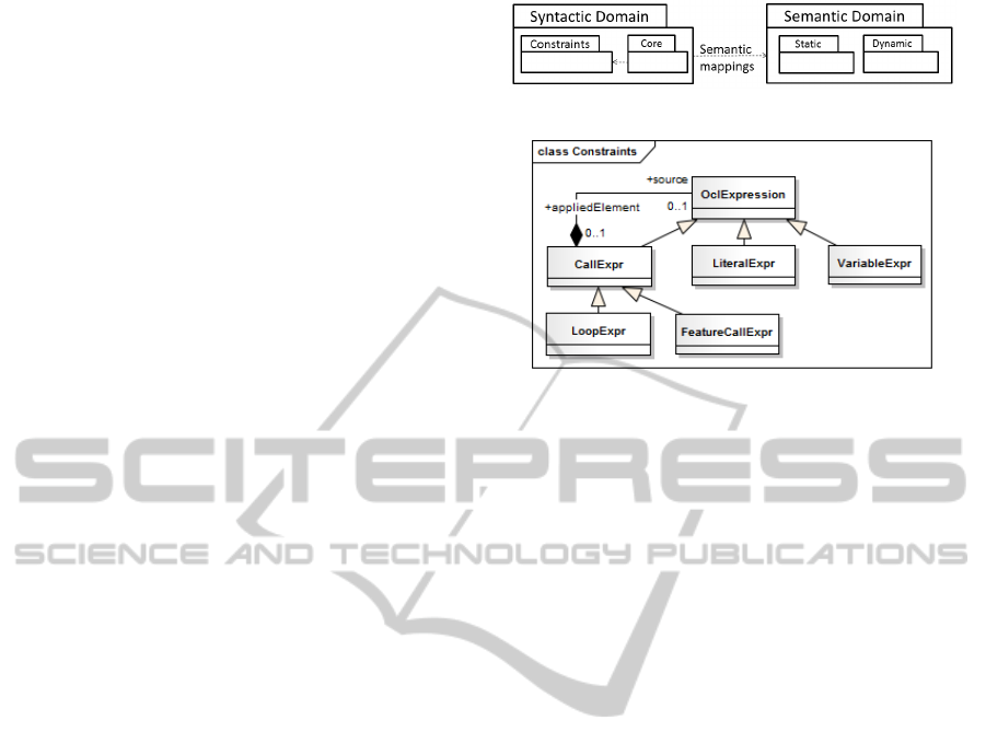
Figure 2: The Framework packages structure.
Figure 3: Class diagram for the ”Constraints” package.
4 ARCHITECTURAL
META-MODELS
We propose a framework for describing software ar-
chitecture. Our framework combines systems syn-
tax, semantics and constraints using graph notations.
In this section, we will present the structure of our
framework through a set of meta-models describing
a graph-based combined semantics for UML classes
and interactions, accompanied by OCL constraints.
This structure is described using the package diagram
of figure 2.
4.1 Syntactic Domain
The syntactic domain is expressed using a meta-
model that combines structure, behavior and con-
straints. Our combined meta-model is composed by
two packages: the package ”Core” and the package
”Constraints”, such as the former one uses the last
one, as illustrated in figure 2. The package ”Con-
straints” was directly inspired from the abstract syn-
tax of OCL expressions specified in the OCL spec-
ification document (OCL, 2001). Indeed, it is com-
posed by the subset of OCL constraints that have been
covered by the work in (Zoubeir et al., 2013) on the
expression of OCL constraints using graphs. In that
work, a set of Graph Constraint Patterns (GCP) was
proposed, representing the transformation of a sub-
set of OCL constraints into graphs. The class dia-
gram corresponding to the package ”Constraints” is
depicted in figure 3.
The package ”Core” constitutes a simplified ver-
sion of the UML class diagram meta-model, in which
we introduced the behavioral notions of interactions.
The class diagram corresponding to the ”Core” pack-
MODELSWARD2015-3rdInternationalConferenceonModel-DrivenEngineeringandSoftwareDevelopment
348
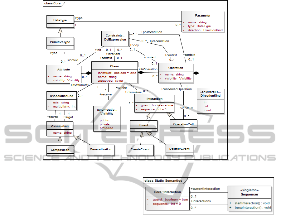
Figure 4: Class diagram for the ”Core” package.
age is illustrated in figure 4. An interaction is iden-
tified by a sequence number and a Boolean expres-
sion named guard. Interactions have two forms: syn-
chronous interactions represented by event sending,
and asynchronous interactions corresponding to op-
eration calls. An interaction takes place between a
sender and a receiver, presented as classes in the com-
bine meta-model. Working with GTSs, the sender
and receiver of an interaction will be represented in
instance graphs by instances of classes, which corre-
sponds to objects in UML.
In this combined meta-model, constraints can be
defined on classes, attributes and operations, the el-
ements constituting the possible contexts of a con-
straints.
4.2 Semantic Domain
The semantic domain is composed by two packages
for the static and dynamic semantics. The static se-
mantics can be represented by meta-modeling. In
figure 5, we present the static semantics of interac-
tions. The sequencer can be regarded as a global vari-
able whose responsibility is to order the sequence of
interactions, and consequently the invocation of the
GTRs corresponding to the model operations. Con-
cerning the dynamic semantics, we did not describe
it by meta-modeling. Inspired by the DMM approach
and most works in the field, we chose to describe the
dynamic semantics and particularly the operational
Figure 5: Class diagram for the Static Semantic package.
semantics using GTRs. Indeed, these transformation
units permit to describe by a transition system what
an object does through a given method.
4.3 Semantic Mappings
The semantic mappings permit to assign a meaning
for each syntactic element. Defining the semantics of
a visual language cannot be complete without a pre-
cise description of the relations that map every syntac-
tic element to a set of semantic elements. The main
semantic mappings in our proposal are depicted in fig-
ure 6. In our semantics, a class is described by a typed
node, an attribute by a valued node and an operation
by a GTR.
Our contribution manifests essentially in the se-
mantic mappings that assign GTRs to constraints, and
scenarios to interactions.
The first mapping is described in details with an
illustrating example in (Zoubeir et al., 2013). It pro-
poses a set of Graph Constraints Patterns (GCP) that
represents the transformation of OCL expressions to
ACombinedGraph-basedApproachforSystemsDesignAndVerification
349
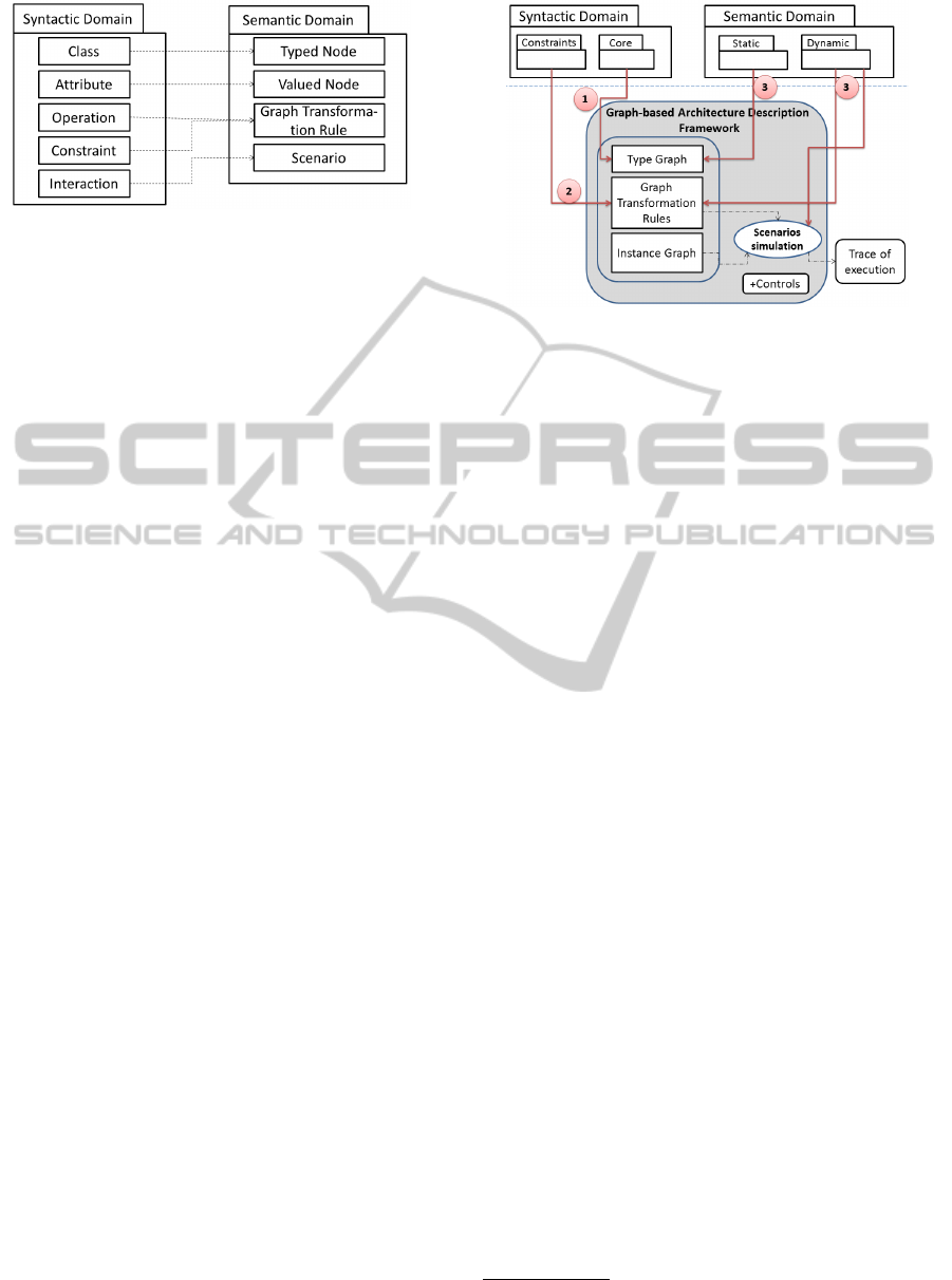
Figure 6: Semantic mappings.
graphs, and then explains how to express OCL con-
straints using GCP within GTRs. The second map-
ping assigns scenarios to interactions. As an interac-
tion is defined as ”a unit of behavior that focuses on
the observable exchange of information between (...)
elements” (UML, 2000), we assume that the execu-
tion of a sequence of interactions can be interpreted
as a possible scenario of the modeling system behav-
ior. In the context of GTSs, a scenario is the ordered
execution of a sequence of GTRs, scheduled using the
mechanism of controls, which constitute a sort of con-
trol programs that permit to schedule the execution of
different rules.
We propose to use typed attributed graphs in or-
der to describe models syntax and semantics. Fig-
ure 7, which is a refinement of figure 1, illustrates
the correspondences between syntactic and semantics
elements, and GTSs. Syntactic elements are repre-
sented in GTSs using typed graphs. Constraints, how-
ever, are described by GTRs, whether as part of meth-
ods operational semantics transformation rules, or as
empty-side effect transformation rules that represent
invariants. In the semantic domain, while static ele-
ments are also described in type graphs, the dynamic
ones will be represented by GTRs, which, scheduled
as scenarios using controls, can be simulated and in-
terpreted within GTS. Simulation constitutes an im-
portant feature offered by GTSs that allows the de-
signer to analyze in depth the obtained results. In
fact, the execution of GTRs on a given graph instance
can be regarded as a labeled transition system that de-
scribes the system’s different states during the simu-
lation.
4.4 Transformation to Graphs
The transformation of a combined model to a GTS is
obtained through three major steps. These steps differ
by their implementation and their possibility of au-
tomation, as detailed in the following paragraph and
depicted in figure 7:
1. Step 1: the first step consists of the transforma-
tion of the combined meta-model of the pack-
Figure 7: Correspondence between GTS components and
the syntactic and semantic domains.
age ”Core” (cf. figure 4) into a corresponding
type graph. Similar transformations were de-
fined for class diagrams (Gogolla and Richters,
1998), and some of them are supported by tools,
such as the tool ”ecore2groove” from the toolset
GROOVE
1
. Our transformation is implemented
using the OMG model transformation standard
Query/View/Transformation (QVT) (QVT, 2008),
such as the source meta-model is the package
”Core” (without representing the constraints, and
containing the semantic class ”Sequencer”), and
the target one is a meta-model for type graphs.
2. Step 2: the second step correspond to the trans-
formation of the constraints defined on the model
into graph transformation systems. This step is
carried out using the Graph Constraint Patterns
(GCP) (Zoubeir et al., 2013).
3. Step 3: the third step corresponds to the expres-
sion of the operational semantics of the model op-
erations using GTRs. This kind of operational se-
mantics expression is widely used in graph-based
software engineering (Hausmann, 2005; Kuske
et al., 2002; Gogolla et al., 2003; Holscher et al.,
2006). This is a manual step that depends on the
designer and the designed system.
Once transformed and in order to be simulated, in-
stances of the model have to be created, in the form
of instance graphs. On these instance graphs, GTRs
can be applied according to different scenarios, and
constraints can be defined and checked on the gener-
ated state space. In the next section we will explain
our proposal for graph-based constraints verification.
1
GRaphs for Object-Oriented VErification, url: http://
groove.cs.utwente.nl
MODELSWARD2015-3rdInternationalConferenceonModel-DrivenEngineeringandSoftwareDevelopment
350

5 GRAPH-BASED VERIFICATION
One important feature of a software architecture de-
scription framework is to offer the possibility of defin-
ing and checking constraints and properties of the
modeled systems. In this paper we focus on two lev-
els of constraints: the model level constraints and the
meta-level constraints. The verification of the first
level of constraints consists on the check of a set of
user constraints defined on the designed system in
order to monitor its structure and behavior. Usually
these constraints are defined on UML model using
the constraints language OCL. As we mentioned ear-
lier, the definition of OCL expression semantics us-
ing graphs and their transformation into graph con-
straints patterns used within GTSs is studied and de-
tailed in (Zoubeir et al., 2013). In this section, we will
focus on the meta-level verification, which consists
generally on the set of well-formedness rules ensur-
ing that a given model is satisfying its meta-model.
For that, we will propose semantics for interactions,
and express it using graphs. Then we will define
some well-formedness rules for interactions and ex-
press them as graph transformation units. For the rep-
resentation of our GTRs we used the GROOVE no-
tation, which combines the rules left hand side, right
hand side and negative application conditions in one
view, and distinguishes them using colors. We also
relied on GROOVE model checker in order to check
our graph constraints.
5.1 Interaction Semantics
The semantics of interactions corresponds to the or-
dered execution of the different operation calls and
event sends, according to the order given by the de-
signer for a particular scenario. We decompose this
semantics into two dependent parts: the interaction
sequencing and the interaction execution.
• Interaction sequencing: The execution of a sce-
nario starts when the current interaction of the
sequencer points to the interaction with the se-
quence 1, if it is available (method ”startInterac-
tion()” in class ”Sequencer”, figure 5). The fol-
lowing interactions are traced by pointing the se-
quencer to the next available interaction (method
”traceInteraction()” in class ”Sequencer”). An in-
teraction is available when its guard, whenever it
exists, is true. The guards are evaluated to true if
they are not explicitly represented. The behavior
of these methods can be expressed using OCL pre
and post-conditions as follows:
1. context Sequencer::startInteraction() :
OclVoid
pre: let i:Interaction = interactions->
select(j|j.sequence=1)-> first() in
i.guard = true
post: currentInteraction.sequence=1
2. context Sequencer::traceInteraction() :
OclVoid
pre: let i:Interaction = interactions->
select(j|j.sequence =
currentInteraction.sequence+1)
->first() in i.guard = true
post: currentInteraction.sequence =
currentInteraction@pre.sequence + 1
The first constraint expresses that in order to start
the interactions, the interaction with sequence 1
should have a guard evaluated to true. Once the
interactions started, the current interaction of the
Sequencer will point on this particular interaction.
The second constraint concerns the rest of inter-
actions. It also monitors the verification of the
guard of the next interaction before pointing the
Sequencer on it.
The operational semantics of these two methods
can be formalized using GTRs, and the OCL pre
and post-conditions defined on them will be ex-
pressed within these. The corresponding GTRs
are depicted respectively in figures 8 and 9. In
these rules we chose to represent guards in a neg-
ative form, since they are considered true if they
do not exist. So the rule of figure 8 consists on
pointing the sequencer current interaction on the
interaction with the sequence 1, if its guard is not
false. And the rule of figure 9 deletes the current
interaction of the sequencer and pointes it on the
interaction with the next sequence, if its guard is
not false.
• Interaction execution: The execution of an inter-
action corresponds to the invocation of an oper-
ation in the case of operation calls, or the send-
ing of a signal in the other cases. The mechanism
of invocation can be expressed within GTSs using
controls. Indeed, the execution of interactions in
a given order constitutes a scenario of a possible
behavior of the modeled system.
Executing interactions scenario will be performed by
alternating interactions sequencing and execution.
5.2 Well-formedness Verification
We assume that the use of GTSs to express well-
formedness rules has many advantages. The most im-
portant are: (1) Rules are expressed using the same
formalism as models: uniformity and semantic inte-
gration, hence there will be no need to use hetero-
geneous formalism to express models and constraints
ACombinedGraph-basedApproachforSystemsDesignAndVerification
351
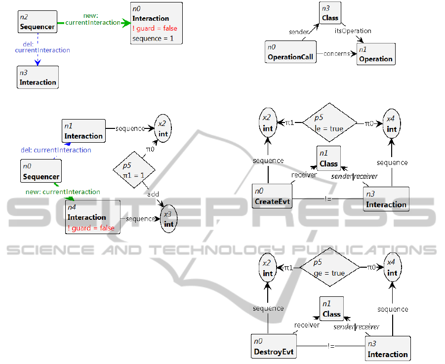
Figure 8: GTR for method ”startInteraction()”.
Figure 9: GTR for method ”traceInteraction()”.
(such as the graphical UML and the textual OCL), (2)
Rules can be formally checked using model checking,
and (3) Rules can be simulated in order to parse the
states violating the given rules, in the state space ad-
jacent to the instance graph.
The well-formedness rules defined on the meta-
model of package ”Core” can be expressed using
OCL. For example, we present the following well-
formedness rules, expressing that an operation call
concerns an operation belonging to its receiving ob-
ject, and that an object cannot be the source or target
of an interaction before it is created or after its de-
struction:
1. context OperationCall
inv: self.receiver.itsOperation->includes
(self.concernedOperation)
2. context CreateEvt
inv: self.receiver.interaction->forAll
(i:Interaction |self.sequence < i.sequence)
3. context DestroyEvt
inv: self.receiver.interaction->forAll
(i:Interaction |self.sequence > i.sequence)
The well-formedness rules are presented as invariants
attached to the meta-model elements. They can be
transformed into empty side-effect GTRs, that should
be checked using model checking in order to verify
whether the corresponding invariant holds for all the
states while the whole simulation. These GTRs are
depicted in figures 10, 11 and 12. An expression can
be presented in its negative form as undesirable prop-
Figure 10: GTR corresponding to the first well-formedness
rule.
Figure 11: GTR corresponding to the second well-
formedness rule.
Figure 12: GTR corresponding to the third well-formedness
rule.
erties, and verified to be never true on the state space,
as for the two latter rules.
Verification can be seen as a fonction of invari-
ants for graph instances generation, i.e. given a meta-
model, a set of graph transformations expressing its
semantics and a set of invariants, a verification algo-
rithm should be able to generate a set of graph in-
stances as test cases by analyzing the invariants.
6 CONCLUSION
In this paper we defined a robust and flexible frame-
work for software architecture description that per-
mits to facilitate, improve and in certain situations
automate analysis on this architecture. In our pro-
posal, we relied on Graph Transformation Systems
to describe systems syntax, static semantics and dy-
namic semantics. These GTSs are also used to carry
MODELSWARD2015-3rdInternationalConferenceonModel-DrivenEngineeringandSoftwareDevelopment
352

out meta-level and model-level constraints definition
and verification, based on the notion of graph con-
straints. We assume that our framework is fully inte-
grated within graphs, which guarantees compatibility,
homogeneity and robustness.
In our future work, we aim to exploit the proposed
framework in the analysis of systems architecture, in
micro and macro levels, especially those conducted
by transformations. Indeed, we exploited an aspect
of this framework to define a graph-based design pat-
terns decomposition (Zoubeir et al., 2014), and we
aim to evaluate and validate the overall approach us-
ing experimental validation based on a repository of
models.
REFERENCES
Bauer, E. (2008). Enhancing the Dynamic Meta Modeling
Formalism and its Eclipse-based Tool Support with
Attributes. PhD thesis, University of Paderborn, Ger-
many.
Bottoni, P., Koch, M., Parisi-Presicci, F., and Taentzer, G.
(2002). Working on ocl with graph transformations.
In APPLIGRAPH Workshop on Applied Graph Trans-
formation, pages 1–10.
Chan, W. K., Mei, L., and Zhang, Z. (2009). Modeling and
testing of cloud applications. In Kirchberg, M., Hung,
P. C. K., Carminati, B., Chi, C.-H., Kanagasabai, R.,
Valle, E. D., Lan, K.-C., and Chen, L.-J., editors, AP-
SCC, pages 111–118. IEEE.
Dang, D.-H. and Gogolla, M. (2008). On integrating ocl
and triple graph grammars. In Chaudron, M. R. V.,
editor, MoDELS Workshops, volume 5421 of Lecture
Notes in Computer Science, pages 124–137. Springer.
Dang, D.-H., Truong, A.-H., and Gogolla, M. (2010).
Checking the conformance between models based on
scenario synchronization. J. UCS, 16(17):2293–2312.
Engels, G., Hausmann, J. H., Heckel, R., and Sauer, S.
(2000). Dynamic meta modeling: A graphical ap-
proach to the operational semantics of behavioral dia-
grams in uml. In UML, pages 323–337.
Gogolla, M. and Presicce, F. P. (1998). State diagrams in
uml: A formal semantics using graph transformations
- or diagrams are nice, but graphs are worth their price.
In University of Munich, pages 55–72.
Gogolla, M. and Richters, M. (1998). Transformation rules
for uml class diagrams. In Bzivin, J. and Muller, P.-
A., editors, UML, volume 1618 of Lecture Notes in
Computer Science, pages 92–106. Springer.
Gogolla, M., Ziemann, P., and Kuske, S. (2003). Towards
an integrated graph based semantics for uml. Electr.
Notes Theor. Comput. Sci., 72(3):160–175.
Hausmann, J. H. (2005). Dynamic META modeling: a
semantics description technique for visual modeling
languages. PhD thesis, University of Paderborn.
Hausmann, J. H., Heckel, R., and Sauer, S. (2004). Dy-
namic meta modeling with time: Specifying the se-
mantics of multimedia sequence diagrams. Software
and System Modeling, 3(3):181–193.
Holscher, K., Ziemann, P., and Gogolla, M. (2006). On
translating uml models into graph transformation sys-
tems. Journal of Visual Languages & Computing,
17(1):78–105.
Kuske, S., Gogolla, M., Kollmann, R., and Kreowski, H.-J.
(2002). An integrated semantics for uml class, object
and state diagrams based on graph transformation. In
IFM, pages 11–28.
OCL (2001). Object constraint language v 2.3.1.
URL : http://www.omg.org/spec/OCL/2.3.1, visited
10/07/2014.
Plotkin, G. D. (1981). A structural approach to operational
semantics. Technical report, University of Aarhus.
QVT (2008). Meta object facility (mof) 2.0
query/view/transformation (qvt). URL : http://
www.omg.org/spec/QVT/, visited 10/07/2014.
Rensink, A. and Kleppe, A. (2008). On a graph-based se-
mantics for uml class and object diagrams. ECEASST,
10.
Rutle, A., Rossini, A., Lamo, Y., and Wolter, U. (2012). A
formal approach to the specification and transforma-
tion of constraints in mde. J. Log. Algebr. Program.,
81(4):422–457.
UML (2000). Unified modelling language superstructure
v 2.4.1. OMG Document Number: formal/11-08-06,
Standard document URL: http://www.uml.org/, vis-
ited 10/07/2014.
Varro, D. (2002). A formal semantics of uml statecharts by
model transition systems. In Graph Transformation,
pages 378–392.
Winkelmann, J., Taentzer, G., Ehrig, K., and K”uster, J. M.
(2008). Translation of restricted ocl constraints into
graph constraints for generating meta model instances
by graph grammars. Electronic Notes in Theoretical
Computer Science, 211:159–170.
Zoubeir, N. and Khalfallah, A. (2010). Synchronization of
the static and dynamic views in rts modeling. In Work-
shop en Informatique et Applications WIA 2010, pages
81–85, Tunisia.
Zoubeir, N., Khalfallah, A., and Ahmed, S. B. (2014).
Graph-based decomposition of design patterns. In-
ternational Journal of Software Engineering and Its
Applications (IJSEIA), 8(2):391–408.
Zoubeir, N., Khalfallah, A., and Benahmed, S. (2013). Em-
bedded Computing Systems: Applications, Optimiza-
tion and Advanced Design, chapter Expressing and
Validation OCL Constraints using Graphs, pages 93–
107. IGI Global.
ACombinedGraph-basedApproachforSystemsDesignAndVerification
353
