
Periodic Patterns Recovery for Multicamera Calibration
Lorenzo Sorgi and Andrey Bushnevskiy
Technicolor R&I, 30625, Karl-Wiechert Allee 74, Hannover, Germany
Keywords:
Multicamera Calibration, Pattern Recovery, Partial Calibration Pattern Visibility, Calibration Pattern Occlu-
sion, External Calibration, Calibration Pattern Offset Removal.
Abstract:
Camera calibration is an essential step for most computer vision applications. This task usually requires the
consistent detection of a 2D periodic pattern across multiple views and in practice one of the main difficulties
is a correct localization of the pattern origin and its orientation in case of partial occlusion. To overcome this
problem many calibration tools require a full visibility of the calibration pattern, which is not always possible,
especially when a multicamera systems are used. This paper addresses the specific problem of consistent
recovery of the calibration pattern, captured by a multicamera systems under the condition of partial occlusion
of the calibration object in several (even all) calibration images. The proposed algorithm is structured in two
sequential steps aimed at the removal of the rotational and the translational components of the pattern offset
transformation, which is essential for a correct calibration. The paper focuses on two common calibration
patterns, the checkerboard grid and the bundle of parallel lines; however, the technique can be easily rearranged
in order to cope with other classes of periodic patterns. The algorithm effectiveness has been successfully
proven on the simulated data and two real calibration datasets, captured using a fisheye stereo rig.
1 INTRODUCTION
Camera calibration aims at estimation of the inter-
nal and the external parameters of an imaging sys-
tem. The first group collects the parameters describ-
ing the geometry of the image formation process of
each camera, such as focal length and distortion coef-
ficients; the second group of parameters instead pro-
vides a representation of the position and orientation
of each camera in a common reference frame. The
external calibration of course implies a multicamera
systems use.
The calibration pipeline usually starts with the
collection of a set of 2D/3D correspondences by se-
lecting in each image the corners corresponding to a
set of known points in 3D space. In order to simplify
this task, most calibration tools use an object with
an a-priori known geometry, which can be easily de-
tected within an image, either in fully automatic way
or with a minimal user interaction. Different objects,
such as 2D or 3D grids and 1D dotted rod, have been
used for calibration(Zhang, 2000; Faugeras, 1993;
Zhang, 2002); in practice now the 2D black and white
checkerboard has become almost a standard, due to
its simplicity and the high accuracy of the corners de-
tection algorithms.
The main difficulty in the grid detection phase is
the correct localization of the grid origin and the axis
orientation. This problem naturally arises in case of
a partial occlusion of the calibration object, due to its
periodic structure.
In case of a single camera calibration the wrong
localization of the grid reference system is not an is-
sue (Kassir and Peynot, 2010). However, this does
not hold when a rigid multicamera systems must be
calibrated. In this case indeed the additional exter-
nal calibration step, that is aimed at the estimation of
the relative geometry between the different cameras
of the cluster, requires the establishment of a set of
spatially consistent correspondences across the multi-
ple views of the calibration object. In particular it will
be shown in the next sections that the correct recov-
ery of the correspondences is important only across
the images, simultaneously captured by the cameras
in the multicamera rig. This is an easy task in case of
full visibility of the calibration object; however, with
the increase in the number of cameras comprised in
the multiview system, the full visibility constraint be-
comes more complicated to satisfy.
In this work we propose a more flexible solu-
tion, which decouples the object detection phase from
the recovery of the consistent set of correspondences,
62
Sorgi L. and Bushnevskiy A..
Periodic Patterns Recovery for Multicamera Calibration.
DOI: 10.5220/0005281300620067
In Proceedings of the 10th International Conference on Computer Vision Theory and Applications (VISAPP-2015), pages 62-67
ISBN: 978-989-758-089-5
Copyright
c
2015 SCITEPRESS (Science and Technology Publications, Lda.)

suitable for the external calibration. This is done by
introducing an additional stage in the typical calibra-
tion pipeline between the internal and the external cal-
ibration steps, aimed at the grid offset removal be-
tween the multiple camera views.
It will be shown that the set of 2D calibration
points can be corrected by enforcing two implicit ge-
ometrical constraints in the metric camera space: the
rigidity of the camera cluster and the discretized na-
ture of the space from which the grid coordinate offset
is sampled. We will then show in practice how the al-
gorithm can be applied to the offset correction of two
common calibration patterns: a checkerboard grid and
a bundle of parallel lines.
2 RELATED WORK
Most of the existing calibration tools require the full
visibility of the calibration pattern in the each im-
age (Tsai, 1986; Bouguet, 2013; OpenCV, 2014;
Wedekind et al., 2013; Douskos et al., 2009; Heikkila,
2000; Datta et al., 2009; Vo et al., 2011). This so-
lution noticeably reduces the complexity of the grid
detection task at the price of a lower calibration ac-
curacy. Indeed, the enforcement of the full visibility
constraint implies, that the periphery of the image is
only weakly spanned by the grid, whereas a strong
calibration requires points broadly spread across the
whole retinal plane.
Other tools use a pre-marked calibration object in
order to establish the spatially consistent correspon-
dences. (Vaish, 2006; Shu et al., 2003; CAMcal,
2014) for example use a grid with the integrated cir-
cle pattern, (Atcheson et al., 2010; Fiala and Shu.,
2008) embed markers with a unique visual ID that can
be used for resolving the multiview offset ambiguity.
However, this approach increases the complexity of
the 2D calibration pattern as well as the whole cali-
bration pipeline, introducing an additional approach
specific marker detection step.
(Agisoft Lens, 2014; Oyamada et al., 2012) cali-
bration tools are designed in a more flexible way and
capable of handling partially occluded views. How-
ever, those tools are aimed at the single camera cal-
ibration and can not be used with multicamera sys-
tems.
In our opinion, a robust calibration tool should be
able to cope with partially occluded views of the cali-
bration object, arbitrarily oriented with respect to the
cameras in the acquisition cluster. For this reason we
propose the offset removal stage between the internal
and the external calibration, which allows the system
to handle the partial occlusion of the calibration ob-
ject without any pre-marking. Despite the simplicity
of the solution we claim that this provides a notice-
able relief of the needed user interaction and greatly
increases the usability of the calibration tool.
3 SYSTEM OUTLINE
Let us denote with M a point in 3D space and with
G
w,c
= (R
w,c
, T
w,c
) ∈ SE(3), a rigid transformation
between the reference coordinate system w and the
one aligned with the c-th camera axis, where SE(3) is
the space of the rigid Euclidean transformations.
If the coordinates of M are expressed with respect
to w, then projection from the 3D space onto the cam-
era retinal plane is described by the equation
m ∼ K · nl (G
w,c
◦ M;θ
d
), (1)
where G ◦M = R M+T is the coordinate transforma-
tion induced by G, K is a camera matrix and nl(x; θ
d
)
is the non linearity, parameterized by the vector θ
d
,
that models the lens distortion (Hartley and Zisser-
man, 2000).
The Internal Calibration is the process of estimat-
ing K and θ
d
using a set of 2D/3D correspondences
{M
i
, m
i
}
i=1...N
. Usually the 2D points are extracted
from one or multiple views of an ad-hoc designed cal-
ibration object, such as a checkerboard and the refer-
ence coordinate system w is implicitly defined by the
calibration object pattern itself, for example assuming
the origin in one of the corners of the grid and the axes
are aligned with the grid directions.
A typical issue arises when the calibration object
is partially occluded in some image. In this case the
grid origin and the axis orientation cannot be unam-
biguously retrieved from the image content, and the
correspondences with the 3D coordinates of the object
can be defined only up to a common roto-translational
offset. We denote this offset as δG = (δR , δM) ∈
SE(3), where δR is a rotational component and δM
is a translational component of the offset. As usually
the grid detection is run independently in each image,
we assume that the extracted patterns are affected by
a different offsets.
The space of feasible offsets affecting the point
coordinates of an image is a discrete subspace of the
Euclidean transformation space and depends on the
specific symmetry of the pattern. For example, it is
easy to see that for a 2D grid (Fig. 1(a)) the feasible
offset can be defined as
(
δM = [δX δY 0]
T
: (δX, δY ) ∈ Z
2
δR = R
Z
(θ) : θ ∈ {0,
π
2
, π,
3π
2
}
, (2)
PeriodicPatternsRecoveryforMulticameraCalibration
63

(a) (b)
Figure 1: Periodic calibration patterns, the checkerboard (a)
and the parallel line bundle (b).
where R
Z
(θ) denotes a 3D rotation about the Z axis.
A different example is given by the line bundle pat-
tern shown in Fig. 1(b). Its 1D symmetry implies
θ ∈ {0, π} and δX ∈ R. In general the appropriate off-
set space (2) can be defined for every periodic pattern
and the proposed grid recovery algorithm remains un-
changed.
Let us denote with
ˆ
M = δG ◦ M the point of the
calibration pattern in 3D space, affected by the offset
(2). By integrating the previous equation into the pro-
jection equation (1), one can see that the exploitation
of the corrupted 3D grid points
ˆ
M leads to an incor-
rect camera pose estimation given by:
ˆ
G
w,c
= G
w,c
◦ δG
−1
c
, (3)
where δG
c
is the offset for the c-th camera.
We can then infer that the improper identification
of the pattern from a set of calibration images implies
a wrong estimate of the camera pose corresponding to
each view, but does not interfere with the estimation
of the internal parameters. This is the reason why the
full visibility constraint can be simply dropped for the
purpose of the single camera calibration.
For a cluster of cameras rigidly mounted on a
common chassis, the external calibration, comprised
of the pose of each camera within the cluster, must
be estimated as well. If we align the cluster reference
system with the first camera, identified by the index 0,
then the external calibration of the c-th camera can be
computed by sequentially combining the pose trans-
formations (3) of the two cameras with respect to the
calibration object:
G
0,c
= G
w,c
◦ G
−1
w,0
, (4)
where G
w,0
is a transformation between reference co-
ordinate system w and the coordinate system of the
first camera 0. Using the offset-affected camera poses
(3) to estimate G
0,c
one obtains
ˆ
G
0,c
= G
w,c
◦ δG
−1
c
◦ δG
0
◦ G
−1
w,0
, (5)
where δG
0
is the offset of the first camera.
The equation (5) shows that for a reliable external
calibration the offset affecting two views do not have
to be necessarily removed. It is sufficient to equal-
ize the offsets to remove them from the eq. (5). In a
practical calibration scenario, when several multiview
captures are processed, the pattern origin and orienta-
tion extracted from the reference camera images can
be considered offset-free and the offset in the views
of the other cameras has to be accordingly corrected.
This is a sufficient correction for a reliable external
calibration. The residual offset affecting the reference
view implies only a wrong estimate of the absolute
pose of the cluster corresponding to each snapshot,
which is anyway outside of the scope of the external
calibration.
Following these two observations, we designed
a multicamera calibration tool comprised of four
phases: calibration object detection, internal calibra-
tion, object pose offset correction and external cali-
bration. The first step extracts the calibration object
independently from each image, without any multi-
view consistency check. The second step estimates
the internal parameters of each camera. The third step
corrects the offset of the pattern coordinates, making
it constant within each set of simultaneous captures
and the last step estimates the cluster multiview ge-
ometry in a unique optimization framework.
This paper focuses specifically on the third step,
which up to our experience has never been addressed.
We claim that it plays an important role in the design
of a user-friendly calibration tool as it allows a suc-
cessfully calibration of a multicamera system relying
only on the knowledge of the pattern topology; the
knowledge of the pattern size and the full visibility in
each image are not required anymore.
In the next sections we show how the object offset
can be corrected in a two consecutive phases, address-
ing the reduction of the rotational and the translation
components of the offset from each calibration view.
3.1 Rotational Offset
Rewriting the rotational component of the c-th camera
pose using the transfer via the reference camera (5)
together with eq.(3) we obtain:
R
w,c
= R
0,c
R
w,0
=
ˆ
R
w,c
δR
c
, (6)
where δR
c
is the rotational component of the offset
in the c-th camera view. By definition (2) δR
c
is a
rotation around z axis, therefore one can remove δR
c
from the eq.(6) multiplying both sides by z:
R
0,c
R
w,0
z =
ˆ
R
w,c
δR
c
z =
ˆ
R
w,c
z. (7)
Given a set of F multicamera captures with the corre-
sponding camera pose estimates, for each camera of
the cluster we can stack F equations in the form of
VISAPP2015-InternationalConferenceonComputerVisionTheoryandApplications
64

(7). Relaxing the constraint (2) an estimate of the ro-
tational component of the external calibration can be
computed as the solution of the following optimiza-
tion problem:
R
0,c
= min
R ∈SO(3)
∑
f ∈[0,F−1]
R · R
w,(0, f )
z −
ˆ
R
w,(c, f )
z
2
.
(8)
This is a typical rotation fitting problem (8), which
can be solved in closed form via spectral matrix anal-
ysis if at least two non degenerate vector correspon-
dences are given (Kanatani, 1994). The rotational off-
set components of each view are then extracted from
(6) and projected onto the discrete offset space (2):
θ
(c, f )
= argmin
θ∈{0,
π
2
,π,
3π
2
}
R
Z
(θ) −
ˆ
R
T
w,(c, f )
R
0,c
R
w,(0, f )
δR
(c, f )
= R
Z
θ
(c, f )
(9)
We remark that if a calibration pattern other than the
checkerboard is used a different search space should
be considered in (9).
Once the rotational offsets of each image are com-
puted, the corresponding grid coordinates are cor-
rected and the problem is reduced to the case of a pure
translational offset recovery, which is addressed in the
next section.
3.2 Translational Offset
Rewriting the translational component of the c-th
camera pose using the transfer via the reference cam-
era (5) together with eq.(3) one obtains:
T
w,c
= R
T
0,c
(T
w,0
− T
0,c
) = R
w,c
δM
c
+
ˆ
T
w,c
, (10)
where δM
c
is a translational offset in the c-th camera
view. Notice that in (10) we considered a null rota-
tional component of the offset, as at this stage this is
assumed to be already removed. Equation (10) can be
rearranged in the matrix form
A
c
T
T
0,c
|δM
T
c
T
= b
c
, (11)
where
(
A
c
=
h
R
T
0,c
|R
w,c
i
b
c
= R
T
0,c
T
w,0
−
ˆ
T
w,c
(12)
Similarly to the rotational offset, F equations of form
(11) obtained from F multicamera captures can be
stacked for each camera in the cluster resulting in a
over determined non-homogeneous system Ax = b,
with (3 + 2F) unknown parameters in the vector x =
h
T
T
0,c
|δM
T
(c,0)
|... |δM
T
(c,F−1)
i
T
. It can be solved in
a least square sense, provided that F ≥ 3. The un-
constrained solution of the translational offsets is pro-
jected onto discrete space (2) by means of a simple
iterative procedure. In each iteration the system is
solved and T
T
0,c
is dropped from the solution vector
x. The parameter of the remaining subvector with
the smallest fractional part, denoted by x
j
, is selected,
truncated and stored in the final solution. Then the
linear system is accordingly reduced by removing the
corresponding column from the coefficient matrix A
and updating the vector b:
A ← A
( j)
b ← b − x
j
· a
j
,
where a
j
is the j-th column of A and the notation A
( j)
means the removal of the j-th column from the ma-
trix A. The process iterates until the size of the sys-
tem matrix A is reduced to 3 ×3, namely until all the
translational offset components are estimated and the
residual unknown vector is x = T
0,c
.
4 RESULTS
The preliminary evaluation has been performed on
the simulated data in order to verify the applicabil-
ity of the pattern recovery algorithm to a typical cal-
ibration scenario. An acquisition system has been
modeled as a trifocal cluster, with each camera rep-
resented as a 1024x768 pixel sensor and a 50
◦
hori-
zontal field of view lens. Each camera is randomly
located on a sphere of the radius ρ, with the opti-
cal axis pointing towards sphere center, where also
the calibration object is placed. The latter is cap-
tured F times by all cameras under different orien-
tations, producing a calibration dataset of F × 3 im-
ages. The calibration dataset is then twofold cor-
rupted. First the 3D coordinates of the calibration
object corresponding to each view are corrupted by
an offset randomly sampled from the feasible domain
(2). Then the pose of each view is altered by a ran-
dom Euclidean transformation of increasing intensity,
denoted as δG
n
= (R
a
(θ
n
), T
n
), where a is a random
unit norm 3D vector, θ
n
is an angle ranging in the
interval [0; 10
◦
] and T
n
is a random 3D vector with
norm in the interval [0;0.1ρ]. These two uncorrelated
noise sources are introduced in order to simulate the
nature of a real calibration dataset: the transformation
of the 3D calibration object represents the offset (2)
affecting the 3D coordinates of the pattern recovered
from each view, the camera pose transformation sim-
ulates the effect of the noisy image measurements on
the internal calibration and consequently on the cam-
era pose estimation. We remark that the intensity of
this second transformation is consistently higher than
the expected error of the camera pose estimation in a
PeriodicPatternsRecoveryforMulticameraCalibration
65
real calibration scenario. Essentially this means that
we are testing the worst-case scenario.
For each level of noise intensity a new scene is
generated 100 times and the number of unsuccessful
trials is counted. A single trial is assumed unsuccess-
ful if any of the offset parameters is incorrectly esti-
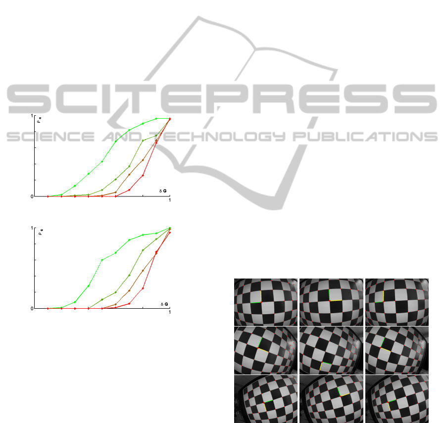
mated. In Fig. 2 the performance measure ρ
e
, given
by the ratio of unsuccessful trials over the total num-
ber of trials, is plotted against the noise intensity level.
The results obtained from simulated data confirm that
the proposed technique provides a reliable mean for
the automatic grid recovery in a multicamera cali-
bration tool. Indeed, in a real scenario a number of
F ≥ 10 captures are typically collected and the error
affecting the camera pose estimates is typically within
the range of a fraction of degree. From the plot shown
in Fig. 2 we can observe that the expected error ratio
in this working conditions is essentially zero and the
grid recovery can be considered fully reliable.
(a)
(b)
Figure 2: Results on the simulated data. The colors light
green, dark green, brown and red identify the error ratio ob-
tained for different size of the image set F = {5, 10, 15, 20}.
The camera pose noise δG
n
is expressed in normalized co-
ordinates with respect to the intensity of the noise variables
T
n
and θ
n
.
We further tested the proposed algorithm as a part
of our stereo calibration tool, which is working with
two types of calibration objects: the standard checker-
board and a color-coded pattern embedding two bun-
dles of orthogonal lines. The calibration pipeline is
invoked according to the chosen pattern. The first one
performs the grid extraction, then the internal calibra-
tion, based on the algorithm (Mei and Rives, 2007),
the multiview grid recovery described in sections 3.1
and 3.2, and the external calibration, based on a mul-
tiview extension of (Lepetit et al., 2009). The second
calibration pipeline performs the line features extrac-
tion, then the internal calibration, based on the algo-
rithm (Kanatani, 2009), the multiview grid recovery
and finally the external calibration, based on our un-
published algorithm.
For each calibration session, 10 stereo frames are
captured using a GOPRO 3D HERO System, a stereo
camera comprised of two GOPRO HERO 2 cameras
equipped with a fisheye lens, rigidly coupled within a
common chassis. This camera system turns out to be
particularly hard to calibrate, mostly due to the diffi-
culty in capturing a robust calibration dataset.
The calibration pattern is detected independently
in each image by means of an automatic detector,
that arbitrary locates the origin of the axis orientation,
without any multiview consistency control. This ini-
tial set of correspondences is used to compute the in-
ternal calibration of each camera. In the third calibra-
tion stage the grid offset is removed from each view.
As it was pointed out in section 3, one can assume,
that the grid extracted from the images of the refer-
ence camera is not affected by an offset, therefore the
algorithm should only correct the offset in the images
of secondary cameras of the multicamera system. In
our test the left camera of the stereo rig is taken as
a cluster reference and the grid of the right images
undergoes the offset correction. The results obtained
from this calibration stage are demonstrated in Fig. 3
and 4, presenting three stereopair samples from each
calibration dataset. The detected grid is shown also
in overlay for the left image and for the right image
(before and after the grid offset removal).
Figure 3: A sample of 3 stereopairs extracted from the
2x10 image set processed according to the first calibration
pipeline, (grid object and metric calibration). Each row
shows the data corresponding to a stereopair. From left to
right are shown the corners and the grid axes extracted from
the left image, from the right image and the corrected grid
of right image.
VISAPP2015-InternationalConferenceonComputerVisionTheoryandApplications
66
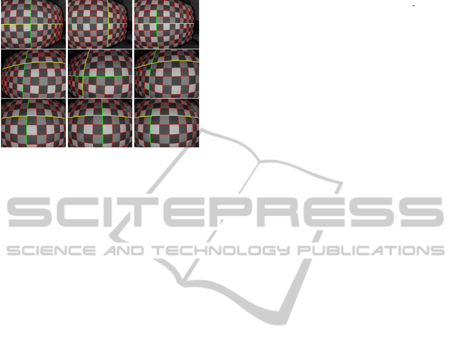
Figure 4: A sample of 3 stereopairs extracted from the
2x10 image set processed according to the second calibra-
tion pipeline, (line bundles object and non-metric calibra-
tion). Each row shows the data corresponding to a stere-
opair. From left to right are shown the grid axis extracted
from the left image, from the right image and the corrected
grid of right image.
The obtained results show that a periodic pattern
can be successfully detected across multiple views
only enforcing the rigidity constraint of the camera
system and the discrete nature of the grid detection
indeterminacy.
5 CONCLUSION
In this paper we derived a new technique, that sim-
plifies the extraction of a symmetric 2D grid pattern
across calibration pattern images obtained using mul-
ticamera systems, under the condition of partial visi-
bility of the calibration object without the use of addi-
tional markers identifying the grid origin and the axis
orientation.
The algorithm effectiveness has been proven on
the simulated muticamera and real stereo camera
datasets. We believe that this work provides a use-
ful solution for a problem that inevitably arises in the
context of multicamera calibration and allows for the
design of a user-friendly camera calibration interface.
REFERENCES
Agisoft Lens (2014). Agisoft lens automatic lens calibration
software. http://www.agisoft.ru/products/lens/. [21
August 2014].
Atcheson, B., Heide, F., and Heidrich, W. (2010). Cal-
tag: High precision fiducial markers for camera cal-
ibration. In Proc. VMV, pages 41–48.
Bouguet, J. (2013). Camera calibration toolbox for matlab.
http://www.vision.caltech.edu/bouguetj/calib doc/.
[21 August 2014].
CAMcal (2014). Camcal camera calibration program.
http://people.scs.carleton.ca/cshu/Research/Projects/
CAMcal/. [8 September 2014].
Datta, A., Kim, J., and Kanade, T. (2009). Accurate camera
calibration using iterative renement of control points.
In ICCV Workshop on Visual Surveillance (VS).
Douskos, V., Grammatikopoulos, L., Kalisperakis, I., Kar-
ras, G., and Petsa, E. (2009). Fauccal: An open source
toolbox for fully automatic camera calibration. In
XXII CIPA Symposium.
Faugeras, O. (1993). Three-Dimensional Computer Vi-
sion: a Geometric Viewpoint. MIT Press, ISBN:
9780262061582.
Fiala, M. and Shu., C. (2008). Self-identifying patterns for
plane-based camera calibration. 19(4):209–216.
Hartley, R. I. and Zisserman, A. (2000). Multiple View Ge-
ometry in Computer Vision. Cambridge University
Press, ISBN: 0521623049.
Heikkila, J. (2000). Geometric camera calibration using cir-
cular control points. 22(10):1066–1077.
Kanatani, K. (1994). Analysis of 3-d rotation fitting. IEEE
T-PAMI, 16(5):543–549.
Kanatani, K. (2009). Calibration of ultrawide fisheye lens
cameras by eigenvalue minimization. IEEE T-PAMI,
35(4):813–822.
Kassir, A. and Peynot, T. (2010). Reliable automatic
camera-laser calibration. In Proc. of ACRA.
Lepetit, V., F.Moreno-Noguer, and P.Fua (2009). Epnp:
An accurate o(n) solution to the pnp problem. IJCV,
81(2).
Mei, C. and Rives, P. (2007). Single view point omnidirec-
tional camera calibration from planar grids. In Proc.
IEEE ICRA, pages 3945–3950.
OpenCV (2014). Open source computer vision library.
http://opencv.org/. [8 September 2014].
Oyamada, Y., Fallavollita, P., and Navab, N. (2012). Single
camera calibration using partially visible calibration
objects based on random dots marker tracking algo-
rithm.
Shu, C., Brunton, A., and Fiala, M. (2003). Automatic grid
finding in calibration patterns using delaunay triangu-
lation. Tech. Rep.
Tsai, Y. R. (1986). An efficient and accurate camera cal-
ibration technique for 3D machine vision. In Proc.
CVPR.
Vaish, V. (2006). The stanford calibration grid de-
tector. http://graphics.stanford.edu/software/findgrid.
[21 August 2014].
Vo, M., Wang, Z., luu, L., and Ma., J. (2011). Advanced
geometric camera calibration for machine vision. Op-
tical Engineering, 50(11).
Wedekind, J., Penders, J., Howarth, M., Lockwood, A. J.,
and Sasada, K. (2013). Using generic image process-
ing operations to detect a calibration grid. Tech. Rep.
Zhang, Z. (2000). A flexible new technique for camera cal-
ibration. IEEE Transactions on Pattern Analysis and
Machine Intelligence, 22(11):1330–1334.
Zhang, Z. (2002). Camera calibration with one-dimensional
objects. volume 4, pages 161–174.
PeriodicPatternsRecoveryforMulticameraCalibration
67
