Fundus Imaging Based Affordable Eye Care
Kolin Paul and Vijay Kumar
Amarnath Khosla School of Information Technology, IIT Delhi, New Delhi, India
Keywords:
Glaucoma, Ophthalmoscope, Fundus, Image Processing, Android, OpenCV, CDR Ratio.
Abstract:
India is a developing country. It has a very low doctor to patient ratio and hence affordabe healthcare has
always been a matter of concern. The high cost of diagnostic devices and unskilled or limited skilled clinicians
exacerbate this problem. The treatment of visually impaired patients is a daunting task in India as it requires
periodic examination of eyesight. Devices meant for this check up are expensive and often require high degree
of expertise to operate. In this paper we propose a low-cost, lightweight, handheld, android phone based
fundus imaging device. The application software makes it user-friendly and also can also provide a limited
automatic screening capability of some retinal problems. In this paper, we report the use of this device for
screening of patients for Glaucoma. The paper presents empirical results using patient data from hospitals.
The results indicate that such a device can effectively scale the operations of screening of many eye related
problems in under served areas.
1 INTRODUCTION
There are more than 285 million people worldwide
suffering from some form of visual impairment. Out
of them, 39 million are victims of preventable blind-
ness caused by cataracts (51%), Glaucoma (8%),
child blindness (5%), trachoma etc. According to
a recent WHO report 90% of these people live in
developing countries that lack specialized medical
services, sophisticated medical equipment and clin-
icians (BlindnessCause1; BlindnessCause2). Many
of these are cases of preventable blindness like glau-
coma. Currently, in India, it is estimated that there
are 12 million people suffer from glaucoma and the
majority of them are undiagnosed (Thomas). This
clearly suggests that many cases of of visual im-
pairment can be mitigated by early stage detection.
For this to be possible a periodic but comprehensive
examination of the eye is mandated. The diagnos-
tic equipment (Optical Coherence Tomography, Hei-
delberger Retinal Tomography, Fundus Camera, Slit
Lamp etc.) employed for eye examination are bulky,
expensive and a trained technician is required to han-
dle them. In under served areas, the large number of
patients and time constraints of available opticians or
ophthalmologists are significant constraints and there
is a need for an innovative solution. To address these
problems we have developed a hand held low cost
fundus imaging device coupled to the smart phone de-
vice that could help in the early detection of the eye
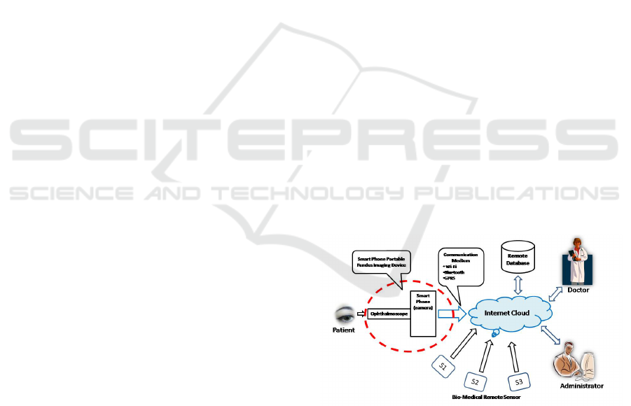
Figure 1: Working of mobile based fundus imaging sensor.
related ailments.
In recent times the smartphone has emerged as a
versatile mobile compute platform. The relative ease
of using a Smartphone based medical devices for var-
ious physiological parameter monitoring can provide
cost effective solutions to the problems of portability.
A Smartphone can be interfaced with a low cost unit
for examining the interior surface of eye, termed as
Fundus which is located opposite to the eye lens and
includes the retina, optic disc, macula and fovea, and
posterior pole. It can be examined using an ophthal-
moscope. Image acquisition of the Fundus is the most
critical aspect of the design — ophthalmologists use
high resolution fundus imaging devices for the same.
The proposed Fundus imaging device integrates the
phone’s inbuilt camera with an ophthalmoscope. A
mobile case has been prototyped for coupling the oph-
634
Paul K. and Kumar V..
Fundus Imaging Based Affordable Eye Care.
DOI: 10.5220/0005285006340641
In Proceedings of the International Conference on Health Informatics (HEALTHINF-2015), pages 634-641
ISBN: 978-989-758-068-0
Copyright
c
2015 SCITEPRESS (Science and Technology Publications, Lda.)
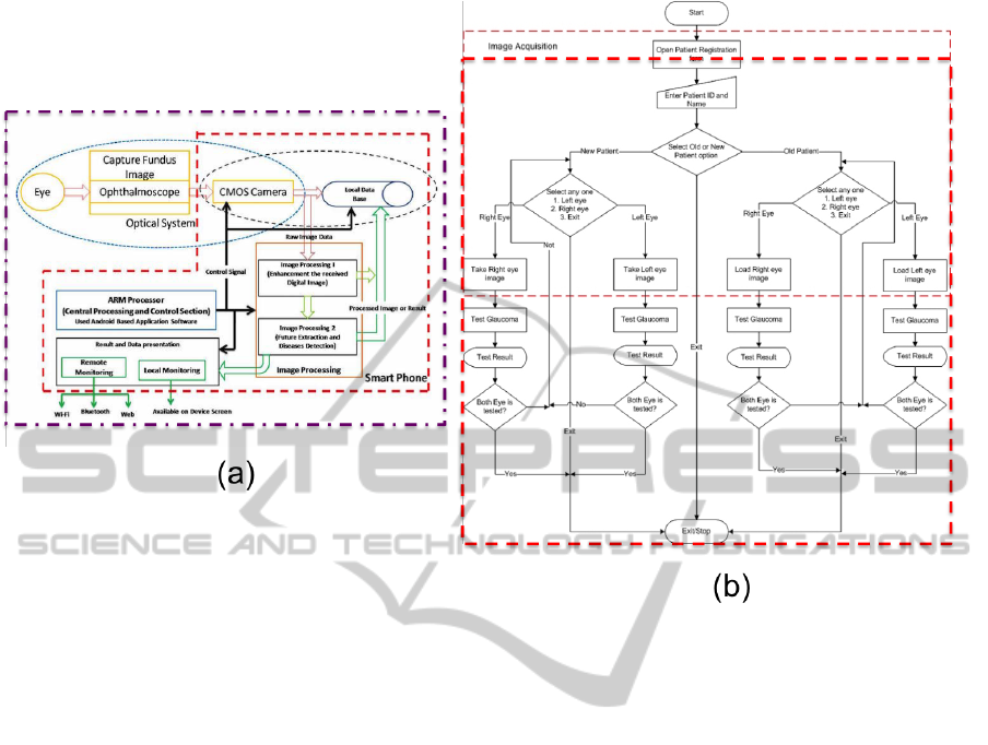
Figure 2: (a)System Architecture and (b) Application software Flow chart.
thalmoscope to the phone. Android based application
software enables the capture of fundus Image/Video.
The application enhances the quality of the captured
image/video and detects the presence of Glaucoma.
The rest of the paper has been organized are fol-
lows. We begin with a high level system overview,
which briefly discusses the system architecture and
its functional sections i.e. image acquisition, storing,
processing and diseases determination. Next, we de-
scribe the hardware and application software of low
cost fundus imaging device. Finally we provide ex-
perimental results of using the device along with vali-
dation results of hospital trials, to illustrate the porta-
bility, scalability and adaptability of the proposed so-
lution.
2 DESIGN OVERVIEW
In this section we outline the design of a Fun-
dus Imaging device subject to constraints of Cost,
Bulkiness, Portability and adaptability. As men-
tioned earlier, the device is based on the Smart-
phone. The Device application software enables a
semi trained/untrained user to operate the system for
detecting certain eye ailments. This has been made
possible by embedding the Optical (image captur-
ing unit), Computing (Microprocessor), Commu-
nication media (Wi-Fi, Bluetooth, Web etc.) and
Database functionalities into a single device shown in
Figure 2a. As illustrated in the figure, the device con-
sists of different function blocks which are described
below:
• Optical System.
This block captures the magnified fundus image
with a camera — typically CMOS in nature. The
key innovation in the solution is to replace the
eye of the ophthalmologist by the smart camera
based CMOS sensor to capture the image of the
patient’s fundus as shown in Figure 4. We use a
smart phone of high resolution (> 5MP) Camera
for the same purpose. We have also designed and
built a custom mobile phone holder Rapid Proto-
type model to attach the Mobile phone camera to
the ophthalmoscope.
• Image Acquisition and Data Management
The Smartphone CMOS camera captures the
magnified fundus image formed by ophthalmo-
scope and saves the image/video in the phone
memory or SD Card. The data is organized in a
hierarchical method. The image is stored along
with meta data like Patient ID and left/right eye
information.
FundusImagingBasedAffordableEyeCare
635
• Image Processing
This functional block does all the image process-
ing related tasks and it is broadly divided into two
units, viz., Processing-I and Image Processing-II
is shown in Figure 2a. To do the image process-
ing, the device uses Android based application
software and the OpenCV library. The first sec-
tion removes helps to minimize/reduce the noise
present in fundus image by applying appropri-
ate median and other filters. After preprocessing
tasks, the next block performs the tasks related to
detection of ocular ailments (like Glaucoma, Dia-
betic retinopathy etc).
• Central Processing and Control Unit
An ARM based processor is used for overall con-
trol of the device. It uses the smart phone’s inbuilt
ARM Cortex processor and runs the application
software written in Java. The ARM based proces-
sor is able to satisfy the computing specifications
required for image processing and responsiveness
of the application software. The ARM processor
that was used for above operations had the follow-
ing specification:
– CPU clock: 0.8 GHz to 2 GHz
– Core: 1-4
– Instruction Set: ARMv7
• Result and Data Representation
This section is responsible for sharing the fundus
data and results with other device or remote user
via different communication media either locally
or using wireless methods.
The Fundus Imaging system consists of smart
phone and an ophthalmoscope. Specifically, a con-
sumer grade (Samsung Galaxy S3/S4 ) cellular phone
is interfaced to a PanOptic’s ophthalmoscope. The
photo-imaging unit of the phone consists of a flash
light as the illumination source to a 8.0 Megapixel
(MP) camera at the centre to centre separation of
around 10 mm. The ophthalmoscope used provides
an easy entry into the eye, together with a wider field
of view to better observe eye conditions.The unit cap-
tures the fundus image in a JPEG format, which gets
stored in the phone. The image is then processed for
detection of its optical disk and cup, after which the
respective areas are calculated to compute the Cup to
Disc Ration (CDR) for setting up the threshold for
the affected eyes. The image processing operations
as discussed above are built into the Android Appli-
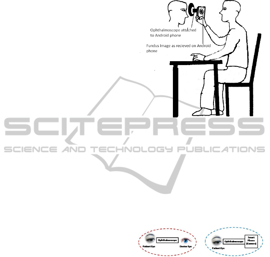
cation. The setup for capturing the fundus image of
a person’s eye using the developed system is shown
in Figure 3. The system is held very close to the per-
son’s eye (for detection of Glaucoma) The real time
application on the phone displays the image. Also,
Figure 3: System Setup for taking Fundus Image,In which
fundus image is appear on mobile phone screen.
it displays the result in a format which can easily be
interpreted.
We now describe the image magnifier system
which is essentially an ophthalmoscope and then de-
scribe the acquisition system which is the smart phone
camera.
Optical System The ophthalmoscope is an optical in-
strument for examining the interior structure of the
eye, especially the back part of eye (fundus), which
includes the retina, optical disk, optical cup, blood
vessel and fovea etc. Ophthalmoscopes are of two
kinds, direct and indirect (Timberlake).
Figure 4: Optical System: Doctor eye is replaced by Cam-
era.
We use PanOptic ophthalmoscope which is very
similar to the traditional ophthalmoscope. However,
there are number of differences – in particular, the
view angle of the PanOptic is 4-5x wider i.e. 25
◦
.
Embedded System. For Image Capturing, Image
processing and Result Sharing we need an advanced
electronic system that has the capabilities described
in the previous section. Modern Smartphones have
many of the required compute capabilities in addition
to having only communication and data sharing capa-
bility. They fulfil the requirements of (a) High res-
olution CMOS camera (b) Centralized Control Sys-
tem to synchronise and control all processes (c) High
computation capability to perform image processing
HEALTHINF2015-InternationalConferenceonHealthInformatics
636

and (d) communication features for sharing result and
data with a potential remote user. The proposed so-
lution has been developed on an Android based Sam-
sung Galaxy S-3 smart phone. The Smart phone cam-
era is able to capture fundus image only when if it is
properly interfaced with hand held portable ophthal-
moscope. In the proposed solution, the physician’s
eye (Figure 4) is replaced by CMOS Camera. For that
we have designed a special type of a phone holder as
shown in Figure 5.
Figure 5: (a) RP model of Case and (b) Ophthalmoscope
attached with mobile phone holder.
The mobile phone case CAD model is shown in
Figure 5, has been designed using SolidWorks soft-
ware. The material used in Rapid Prototype system
for building the case is SLS. Various factors as porta-
bility, light weight, aesthetic looks etc. have been
considered. The round shape on the top centre has
been provided to ensure that the view through the oph-
thalmoscope can be captured on phone’s camera with-
out any obstructions. For a stable fit of the ophthal-
moscope with phone, a holder is built at the bottom.
Also, to ensure easy charging of the phone, a rectan-
gular shape hole is provided at the bottom and one on
the top left for the volume control. The mobile case
when integrated with the Ophthalmoscope is shown
in Figure 5. The mobile can easily be inserted into
the casing.
3 IMAGE ACQUISITION
SOFTWARE
In order to display the fundus image and the results, a
fundus imaging software has been developed. The ap-
plication software works on all Android based Smart-
phones. The application software includes all the
image processing operations needed to calculate the
degree of Glaucoma in the person’s eye. The same
has been achieved using OpenCV Library on Android
platform and performs two major tasks namely (a)
Image Acquisition and (b) Image Processing (Glau-
coma Detection). For all the tasks, application soft-
ware switches to different UI screens thus helping
guide the user at each stage of the application. This
is shown in Figure 2b. As shown in the figure, the
Fundus Image Acquisition step is further divided into
four stages.
• Filling Patient Information. GUI has two text
fields Patient Name and Patient ID. For each
user, patient ID is a must and it must be unique.
Patient ID will help in searching and sorting of
patient data in future.
• Option to use this device as new and old patient.
For both case application will provide separate
GUI windows.
• Separate GUI is provided to select left and Right
eye one by one for taking the fundus image.
• Image capturing GUI provides image retake and
save options. After the capturing operation, the
image is visible on thev GUI so that user can ac-
cept the image quality or redo the entire operation.
All the above four stages of operation in Android
is defined as four different Activities and uses four
different Layouts. Image acquisition is done in four
stages. All stages are defined as Activities in Android
Development environment (ADT). That is described
by the AndroidManifest file and briefly described be-
low:
• BeginActivity: Patient Information Form. This
manages patient related information. User should
enter patient name and Patient ID No in the GUI.
On the basis of patients ID, the application soft-
ware will manage all the related data.
• MidActivity: Select Eye. MidActivity provides
a Menu option to select the eye and patient type
for Fundus imaging. By clicking the button/radio
button, the user makes the choice. The button’s
operation is defined in the Activity Layout file.
• LeftCamActivity/RightCamActivity. In this ac-
tivity application will perform Video/Image aqui-
sition task. In this activity, the application cap-
tures images/video of left and right eye. To cap-
ture Video, application will call native Camera in-
tent. To use intent native Camera again applica-
tion will perform check for all camera permission.
However, in case of old patients, software will au-
tomatically search and select the patient fundus
image.
The next section describes then Android based ap-
plication developed for Glaucoma screening.
4 DETECTING GLAUCOMA
Glaucoma is a neurological disorder that causes dam-
age to optical nerves occurs due to Intra ocular
FundusImagingBasedAffordableEyeCare
637
pressure (IOP). Glaucoma is evaluated by measur-
ing IOP,visual feild and optical disc shape (Cup to
Disc Ratio ‘CDR’ (Narasimhan; Yuji) and ISNT rule
(Harizman)). CDR is one of the main clinical indi-
cations of Glaucoma. In case of glaucomatic eye this
ratio will high as compared to healthy eye.
In the application, we implement the intensity
based segmentation method (Yuji; Wong) to segment
out the optical disk and the cup from the green chan-
nel of ROI. Using the elliptical area formula android
device application software will calculate the area of
the optical disk and cup (Narasimham). After that,
we use the ellipse area formula to find out the area of
segmented region. Finally CDR value is calculated by
taking the ratio of Cup Area and Disc Area. On the
basis of calculating CDR value one can say about the
stage of glaucoma.
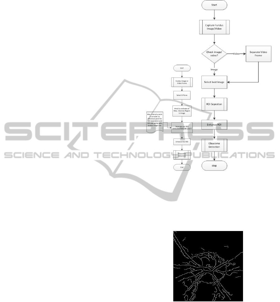
We first discuss the method used to identify the
ROI. We have used OpenCV library to implement im-
age processing operations for the application whose
primary focus to detect the glaucoma in the Fundus
image. The working of this Glaucoma detection soft-
ware is illustrated in the flow chart shown in Figure 6.
The Android application performs image processing
in two stages. In the first stage, image processing soft-
ware performs all the tasks related to ROI separation,
preprocessing and image quality detection. And in the
second stage, the software does Glaucoma detection.
Different algorithms from of Image enhance-
ment (Peli; Paulus) are used to de-noise the captured
image as well as perform operations for detection of a
particular ocular ailment. This includes the following
steps:
1. ROI Extraction. The ROI extraction is shown in
Figure 6. The application software captured fun-
dus image in RGB mode. The extraction of the
optical disk and the cup is done from from the G
plane as it provides better contrast compared to
the other planes.
The centre of the disk will be obtained on the basis
of maximum intensity region in the G plane/Gray
image. The identified maximum intensity point is
considered as a reference point to find out ROI.
Using that value we separate out ROI of pixel
size 300 ×300 pixels or 500 ×500 pixels from the
original image.
2. Preprocessing of Extracted ROI. To differenti-
ate between optical cup and disk, a good qual-
ity of images is desirable. Also, even if the im-
age quality is good but edges are not easily differ-
entiable due to the inappropriate intensity levels,
image improvement is required. To achieve this,
the application performs Histogram Equalization,
Normalization and Filtration of blurred image.
Figure 6: Flow chart for ROI separation and Glaucoma De-
tection.
3. Automatic Image Quality Assignment. Some
time users are not able to differentiate the quality
of images taken by device. We have used tech-
niques described in (Paulus; Giancardo) to check
the image quality.
Figure 7: ROI:Blood Vessel.
• Elliptical Local Vessel Density Measure-
ment. In OpenCV we use different edge func-
tions to find out edges in ROI. On the basis of
density edges in ROI we conclude about the
quality of images. Normally if the image is
good than available edges density is high.
• Histogram Based. The histogram is deter-
mined for the Gray Image. The application then
uses a method described in (Paulus) to find out
the quality of image. Finally the application
HEALTHINF2015-InternationalConferenceonHealthInformatics
638
software applies both methods to find quality
of image.
The application software uses this CDR value to
screen out Glaucoma suspects and health person. In
the proposed solution, one can also capture fundus
video also that will help a clinician to analyse retina in
other ways. The entire process is done on an undilated
eye. The application performs the following tasks one
by one to do the screening:
• Segmentation of Optical Disk and Optical Cup.
Optical disk detection is carried out in the an-
droid application software using the OpenCV li-
brary image processing function. Implementation
is done in following steps:
– RGB Fundus image is converted into a Gray
image: Used OpenCV library function (Fig-
ure 8).
– Histogram equalization of the image pixel in-
tensity: (Figure 8). After equalization, im-
age intensity value lies between 0-255 and it is
helpful in next stage i.e. thresholding.
– Thresholding and Binarization: In the applica-
tion software we used 95% of the maximum in-
tensity as a threshold point for Disk segmenta-
tion. (Figure 8).
The optical cup detection is similar to detection of
optical disk, the only difference being the selec-
tion of the threshold value (here it is 80% of the
maximum intensity gray image). The segmented
Cup is shown in Figure 9.
• Cup to Disk Ratio(CDR). Optical cup size will
increase as compared to optical disk and that will
reflected through Cup to Disk ratio. For a nor-
mal person its value is 0.1-0.3. CDR value plays
key role in our proposed solution for Glaucoma
screening. But in the case of the eye affected with
the disease, the ratio becomes high.
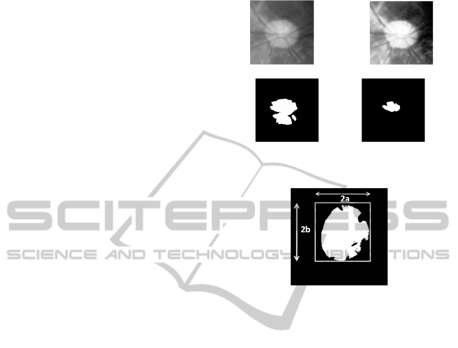
• Segmented Disk/Cup Area To find CDR, firstly
find out the area of Disk and Cup.Used the bina-
rized optical disc and cup to find out correspond-
ing area using the ellipse method (Narasimhan;
Narasimham).
Area = π ∗a ∗ b (1)
Where,
a = half length of major axis ellipse.
b = half length of minor axis of ellipse.
After obtaining the respective areas, the CDR ra-
tio is calculated.
Figure 8: Segmentation: 1. Gray ROI 2. Historarm equal-
ized ROI 3. Segmented optical disc and 4. Segmented opti-
cal cup1.
Figure 9: Elliptical Shape of Segmented disk/cup.
5 EXPERIMENTATION AND
VALIDATION
This section discusses the experimentation conducted
at an Eye Hospital in two stages. In the first stage we
took fundus image of 15 patients to find out a thresh-
old CDR for glaucoma detection. In the second stage
we haved validate the device with more subjects. For
the whole process of experimentation, we have cho-
sen patients randomly and maintain similar test con-
ditions which are enumerated below:
1. Hospital Doctor will first test patient eye for Glau-
coma using Tonometry and Ophthalmoscopy
2. Room Light: Dim room light is used for collecting
fundus image.
3. Patient Condition:
(a) Sitting on a chair in rest position
(b) For Un-dilated eye: Take a fundus image at the
same instant.
(c) For Dilated Eye:Some time patient eye pupil
size is not sufficiently large. In that case doctor
are not able to see larger view of fundus image.
We dilate the eye, so that pupil Diameter will
increase and it will take about 20-30 minutes.
FundusImagingBasedAffordableEyeCare
639
(d) Cataract patient: If a patient is suffering from
cataract than normal fundus imaging is not able
to find clear image of the retina. In that case
this device will be better because of image En-
hancement capability.
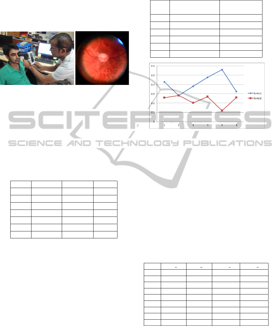
Figure 10: (a) Taking the fundus image colligue in labora-
tory and (b) Fundus image (Cpature by our device from the
hospital).
Repeatability Test
Initially a test was carried out on a healthy participant
in laboratory to verify the repeatability of the device.
In this case we will check segmented cup and disk on
Matlab. Then find its Area and CDR. We got a stable
Table 1: Repeatability Test: Cup and Disc Area for a
healthy person.
S.No. Cup Area Disc Area CDR
1 26829 107980 0.2485
2 23320 107760 0.2165
3 23637 105160 0.2248
4 24014 117780 0.2039
5 28953 118930 0.2434
6 25447 903430 0.2817
7 19195 102310 0.1876
output for the same person repeatedly. Repeatability
test data are shown in Table. 1. From Table 1, mean
and standard deviation obtained from healthy person
is 0.2295 and +/-0.0313 respectively.
Threshold CDR Value for Glaucoma
Screening
After verifying stability of the device, several tests
were performed on participants at the Eye Hospital. It
was observed that the CDR value obtained for the pa-
tients with Glaucoma was always greater than 0.2809.
Whereas, the CDR value obtained for Non Glau-
coma patients was always less than 0.2809 (Table 2
and Figure 11). Hence, a threshold of 0.2809 was
set for screening Glaucoma patients from Non Glau-
coma patients. Also, the mean and standard deviation
obtained for Glaucoma and Non Glaucoma patients
Table 2: CDR values of glaucomatous and health person.
S.No Glaucoma patient Non glaucoma
(CDR) patient(CDR)
1 0.4266 0.2564
2 0.2809 0.2802
3 0.3799 0.2006
4 0.4761 0.2672
5 0.5599 0.1166
6 0.3243 0.2591
Figure 11: Graph: CDR value Curve.
were 0.4080, +/-0.1020 and 0.2300, 0.0619 respec-
tively.
Device Validation
Second stage of device experimentation, device vali-
dation is done in the same eye Hospital with 10 addi-
tional subjects. CDR values for these patient is shown
in Table 3. CDR value 0.2700 is considered as thresh-
old value for this device . In Table 3 result of patient
No 08 is false positive. As for screening device, this
is safer side because in the next stage of retinal diag-
nosis of patient, the problems was identified.
Table 3: Patient diagnosis report using mobile based fundus
imaging device, Here threshold value used for diagonosis is
0.2700.
S.No CDR LE CDR RE Result LE Result RE
1 0.302 +ve
2 0.335 0.522 +ve +ve
3 0.464 0.308 +ve +ve
4 0.0.043 0.168 -ve -ve
5 0.369 +ve
6 0.15 0.195 -ve -ve
7 0.381 0.261 +ve -ve
8 0.263 0.429 -ve False +ve
9 0.205 0.245 -ve -ve
6 CONCLUSION
The mobile phone based low cost, portable fundus
imaging device has been designed and developed to
HEALTHINF2015-InternationalConferenceonHealthInformatics
640

improve accessibility to affordable eyecare. It has
been shown that applications can be built to automati-
cally screen eye related ailments. the paper illustrates
results for screening patients with glaucoma — the
application is being enhanced for detecting other eye
ailments notably diabetic retinopathy. Primary exper-
iments and validation also proves its usability, and
easy handling capability. It has the capability to sup-
port different media of communication to share im-
age/result to remote user. It can be used in primary
health care center, OPD and Health care camp where
fast screening is necessary.
ACKNOWLEDGEMENT
This work was partially supported by Telecommuni-
cation Consultants India Limited (TCIL), DeITY and
IIT Delhi.
REFERENCES
http://www.who.int/blindness/causes/en/index.html
http://www.who.int/mediacentre/factsheets/fs282/en/
index.html
Thomas R.,Glaucoma in India: Current status and the road
ahead. Indian J Ophthalmol.2011.
http://www.ophthalmologyweb.com/Specialty/ Glaucoma/
Darrell M. West,Improving Health Care through Mobile
Medical Devices and Sensors,2013;Center for Tech-
nology Innovation at Brookings.
Timberlake G T, Kennedy M D.The Direct Ophthalmo-
scope:How it Works and How to Use It. 2005.Univer-
sity of Kansas Press.
http://www.aoa.org/
http://www.nei.nih.gov/health/
http://www.android.com/
http://opencv.org/
Peli E., Schwartz B.; Enhancement of fundus photographs
taken through cataracts; Ophthalmology. 1987.
Jan Paulus, Jrg Meier, Rdiger Bock, Joachim Hornegger,
Georg Michelson;Automated quality assessment of
retinal fundus photos;International Journal of Com-
puter Assisted Radiology and Surgery November
2010.
Inoue N., Yanashima K., Magatani K., Kurihara T.; Devel-
opment of a simple diagnostic method for the glau-
coma using ocular Fundus pictures; Conf Proc IEEE
Eng Med Biol Soc. 2005.
K. Narasimhan, K. Vijayarekha, K. A. JogiNarayana, P.
SivaPrasad ,V. SatishKumar; Glaucoma Detection
From Fundus Image Using Opencv; Research Jour-
nal of Applied Sciences, Engineering and Technology
2012.
Harizman N1, Oliveira C., Chiang A., Tello C., Marmor
M., Ritch R., Liebmann J. M.,The ISNT rule and dif-
ferentiation of normal from glaucomatous eyes.,Arch
Ophthalmol. 2006.
Wong DK1, Liu J., Lim J. H., Jia X., Yin F., Li H.,
Wong T. Y.,Level-set based automatic cup-to-disc ra-
tio determination using retinal fundus images in AR-
GALI.,Conf Proc IEEE Eng Med Biol Soc. 2008.
K.Narasimham, K.Vijayarekha; An Efficient Automated
System For GLaucoma Detection using Fundus Im-
age; Journal of Theoretical and Applied Information
Technology, 2011.
Yuji Hatanaka, Atsushi Noudob, Chisako Muramatsuc,
Akira Sawadad, Takeshi Harac, Tetsuya Yamamotod,
Hiroshi Fujitac; Vertical cup-to-disc ratio measure-
ment for diagnosis of glaucoma on fundus images;
Medical Imaging 2010: Computer-Aided Diagnosis,
edited by Nico Karssemeijer, Ronald M. Summers,
Proc. of SPIE Vol. 7624, 76243C.
Ahmed Wasif Reza & C. Eswaran & Subhas Hati, Auto-
matic Tracing of Optic Disc and Exudates from Color
Fundus Images Using Fixed and Variable Thresholds,
Journal of Medical Systems, Feb 2009.
L. Giancardo, F. Meriaudeau, T. Karnowski, E. Chaum, and
K. Tobin, New Developments in Biomedical Engi-
neering. InTech, 2010. Quality Assessment of Retinal
Fundus Images using Elliptical Local Vessel Density.
FundusImagingBasedAffordableEyeCare
641
