WaPT
Surface Normal Estimation for Improved Template Matching in Visual Tracking
Nagore Barrena
1
, Jairo R. S
´
anchez
2
and Alejandro Garc
´
ıa-Alonso
3
1
Interactive Computer Graphics, Vicomtech-Ik4, Donostia, San Sebasti
´
an, Spain
2
Industry and Advanced Manufacturing, Vicomtech-Ik4, Donostia, San Sebasti
´
an, Spain
3
Computer Science and Artificial Intelligent, University of the Basque Country, Donostia, San Sebasti
´
an, Spain
Keywords:
Surface Normal, Template Matching, Markerless Tracking.
Abstract:
This paper presents an algorithm which is an improvement of the template matching technique. The main goal
of the algorithm is to match 3D points with their corresponding 2D points in the images. In the presented
method, each 3D point is enriched with a normal vector that approximates the orientation of the surface where
the 3D point is lying. This normal improves the transfer process of patches providing more precise warped
patches, because perspective deformation is taken into account. The results obtained with the proposed transfer
method confirm that matching is more accurate than traditional approaches.
1 INTRODUCTION
Nowadays, optical tracking methods are used in many
fields like robot navigation or augmented reality. In
essence they establish a relationship between an inter-
nal representation of the real scene (3D point cloud)
and the images which are captured by the camera.
In the case of markerless tracking methods the most
common solutions rely on matching some 3D points
with their corresponding 2D points in each image.
Among the most used techniques are matching us-
ing feature descriptors. These techniques are robust
against illumination, orientation and scale changes.
However, they present some efficiency problems. For
this reason while feature descriptors based methods
are kept for the initial matching, other techniques,
like optical flow, are used to track the 2D correspon-
dences throughout video sequences. As optical flow
estimates iteratively the displacement of each feature
from frame to frame, it is prone to drift. In order
to obtain more accuracy and palliate the drift in the
tracking process, methods like template matching are
normally used.
In these methods, for each 3D point of the point
cloud a patch around its projection from a reference
frame is saved as a reference template. Then template
matching techniques are applied during the tracking.
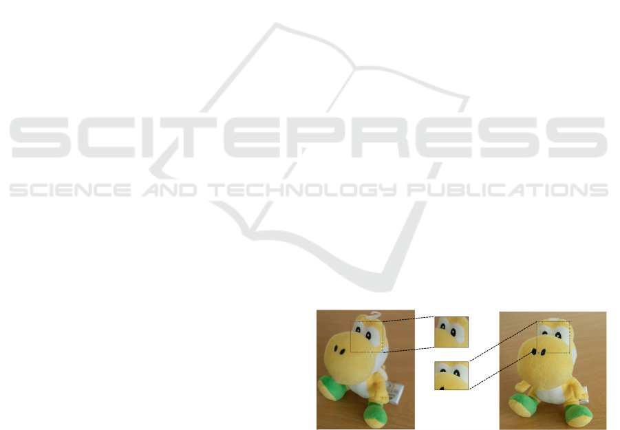
However, due to camera motion and the geometry of
the real scene, the matching with the reference tem-
plate can fail because of perspective deformations, as
can be seen in Figure 1. Nevertheless, in order to
solve the mentioned problems, the reference template
can be warped taking into account the camera position
and the geometry of the real scene.
Figure 1: Perspective deformations.
This paper presents an algorithm denominated
WaPT (Warped Template Patch Tracking). It im-
proves the patch transfer process and generates a more
accurate warped patch. Consequently, the template
matching process is more accurate.
WaPT extends the internal representation of the
real scene: each 3D point will have a normal vector
that approximates the orientation of the real surface
where it is placed on. In this way, the reconstruc-
tion process does not only find 3D points, but it also
approximates their surface normals. WaPT uses this
orientation in order to improve the template matching
process.
The paper is structured as follows. Section 2 re-
views related publications in visual tracking. Section
496
Barrena N., Sánchez J. and García-Alonso A..
WaPT - Surface Normal Estimation for Improved Template Matching in Visual Tracking.
DOI: 10.5220/0005295104960503
In Proceedings of the 10th International Conference on Computer Vision Theory and Applications (VISAPP-2015), pages 496-503
ISBN: 978-989-758-091-8
Copyright
c
2015 SCITEPRESS (Science and Technology Publications, Lda.)

3 describes in detail the WaPT method and the under-
lying template transfer and matching processes. Af-
terwards, Section 4 shows the experiments carried on
to evaluate this proposal, alongside a discussion. The
paper concludes in Section 5 with conclusions and
hints for future work.
2 RELATED WORK
Template matching techniques have been used by sev-
eral authors in order to match 2D features with 3D
points. Markerless tracking methods as visual SLAM
(Davison, 2003) match 3D points of the reconstructed
point cloud with their corresponding 2D points in the
images. In order to achieve this goal, the feature de-
tection and matching is one of the most used meth-
ods. In this way, SIFT (Lowe, 2004), FREAK (Alahi
et al., 2012) and SURF (Bay et al., 2006) are very
robust algorithms thanks to their invariance to illumi-
nation, scale and orientation changes. Consequently
the probability of a correct match is high. However,
the feature detection and matching process requires a
high computational cost.
Some authors like (Barron et al., 1994) use opti-
cal flow techniques to estimate the image velocity, or
the shift of an specific point from frame to frame. Al-
though this method has lower computational cost, the
estimation of the feature displacement is not as accu-
rate as other methods and it is prone to drift.
On the other hand, relatively large image patches
can serve as features. Good examples are provided
by (Davison et al., 2007) and (Klein and Murray,
2007) who use patches as features. In order to match
correctly these patches, they use template matching
methods. The template matching processes use differ-
ent operators to estimate the similarity of the patches.
Sum of absolute difference (from now on SAD) (Wat-
man et al., 2004) is one of them. However, in order to
get better results against changes, for example bright-
ness, there are alternatives like the cross-correlation
coefficient or the normalized cross-correlation coeffi-
cient operators (Szeliski, 2010).
Template matching methods may fail to obtain
the correspondences due to camera motion and per-
spective deformations. Surface orientation can be
used in order to take into account these deforma-
tions. (Molton et al., 2004) suggest a SLAM algo-
rithm which uses a probabilistic method to estimate
the most probable surface orientation in each mea-
surement. Later on, (Davison et al., 2007) make a
simplification: they assume that 3D points always lie
on a planar surface oriented to the camera where they
were first seen. They assume that the appearance of
the patch will not change at all.
However, (Furukawa and Ponce, 2010) obtain
very effective model reconstructions of statues and ar-
chitectural elements. The work emphasizes that the
use of surface orientation helped a lot to obtain such
good results.
For this reason WaPT extends the approach
proposing an analytic method to estimate the real ori-
entation of the 3D point in pre-process, in order to
warp the template patch better and to obtain more ac-
curacy in the matching process.
3 WaPT METHOD
Based on the work by (Davison et al., 2007), 3D
points are considered features that will be projected
into the query images to get the localisation of the
camera in real-time. In order to make this process ac-
curately WaPT follows two main stages:
3D Reconstruction Stage
A 3D reconstruction of the environment is done
and the estimation of a normal vector is calculated
for each 3D point. This normal defines the orien-
tation of the surface where the 3D point is placed
on. This process is run off-line and the main goal
is to get the point cloud of the environment and
the orientation of each 3D point to make the patch
transfer procedure more accurate in the next stage.
Tracking Stage
For each input frame the following steps are done
on-line:
1. Using the normal estimations calculated in the
3D Reconstruction stage the reference template
is warped, i.e a fixed size patch is transferred
from the current image to the reference image
(where the point was first seen during the 3D
reconstruction). Then, using a similarity mea-
surement the transferred patch is located in the
current image, and the center of this patch is
treated as a feature.
2. Then, the vector of features obtained in the pre-
vious step is used to calculate the pose of the
camera.
The following sections are devoted to describe in
detail the two stages of the WaPT algorithm.
3.1 3D Reconstruction Stage
The objective of the 3D Reconstruction Stage (pre-
process) is to generate a 3D representation of the en-
vironment. This representation should be the most
WaPT-SurfaceNormalEstimationforImprovedTemplateMatchinginVisualTracking
497

appropriate for the Tracking stage. The output of this
phase is a point cloud where a normal vector is as-
sociated to each 3D point. Each 3D point lies on a
surface of the environment and its associated vector
approximates the surface normal. To the best of our
knowledge previous work does not address the normal
estimation problem and only computes the 3D points.
The point cloud is obtained using the Structure
from Motion method (Dellaert et al., 2000), which
will be named from now on SfM. SfM combines
multi-view techniques with a Bundle Adjustment pro-
cess (Triggs et al., 2000). Its input is a sequence of
images of the environment. The images used in the
SfM process are denominated keyFrames. The goal
of our work in this paper is to estimate the normal for
each 3D point of the point cloud obtained by SfM.
To achieve this objective a minimization process has
been designed and implemented.
Consider the case shown in Figure 2. There are
two keyFrames where the same point is visible. The
keyFrame where the point was first seen is denom-
inated Reference keyframe. A normal vector is as-
sociated to the 3D point defining a plane. The fig-
ure shows the projections of the 3D point on each
keyFrame. It also shows two patches around the pro-
jected 3D point and the plane defined by the 3D point
and the normal.
Assume the following definitions:
Transferred Patch. A square patch defined around
the projected 3D point in every keyFrame where the
3D point is visible, except the Reference keyFrame.
Reference Patch. The patch obtained when a given
Transferred patch is transferred to the Reference
keyFrame: the warped patch.
The process to obtain a Reference patch is the fol-
lowing one: given any 3D point, its projection onto
the keyFrame is used to define a Transferred patch.
Then, this Transferred patch is back-projected onto
the plane associated to the 3D point. This new poly-
gon is projected onto the Reference keyFrame gener-
ating the Reference patch (see Figure 2).
The objective of the minimization algorithm is to
find the normal that minimizes the image difference
between the two image patches.
This work uses the Levenberg-Marquardt mini-
mization algorithm (Mor
´
e, 1978). This algorithm is
an iterative process, where a random normal is taken
as the initial guess. The plane defined by the normal
is then used to transfer the Transferred patches to the
Reference keyFrame. Afterwards the algorithm eval-
uates the difference between the Transferred patch
and the Reference patch. The minimization algorithm
adjusts the normal so that the difference between all
the Transferred patches with the Reference patch is
the smallest. The algorithm exits when the difference
between the last iteration and the current one does not
exceed a fixed threshold.
Let us explain in detail the enumerated steps:
3.1.1 Feature Plane
In the projective space a plane is defined as shown
in equation (1) (Hartley and Zisserman, 2003). In
order to get it, three points (
~
X
1
,
~
X
2
,
~
X
3
) lying on the
plane are needed.
~
X
1
is used to represent the given
3D point. The other two points (
~
X
2
and
~
X
3
) are cal-
culated using the normal vector and the restriction
imposed by equation (2), where (a,b,c)
T
is the nor-
mal and (x, y, z)
T
the 3D point in the euclidean space.
Take into account that d is defined by equation (3).
This equation presents singularities when the normal
is aligned with one of the main axis.
~
π =
(
~
ˆ
X
1
−
~
ˆ
X
2
) × (
~
ˆ
X
2
−
~
ˆ
X
3
)
−
~
ˆ
X
T
3
(
~
ˆ
X
1
×
~
ˆ
X
2
)
!
(1)
ax + by +cz +d = 0 (2)
d = −(ax
1
+ by
1
+ cz
1
) (3)
3.1.2 Transfer the Patch
Each pixel of the Transferred patch is back-projected
onto the plane, i.e. each pixel of the Transferred patch
defines a point as the intersection of its back-projected
ray and the plane. Then, these points are projected to
the Reference keyFrame. The process can be seen in
Figure 2.
The back-projection of the point in the im-
age is defined by equation (4), where P
+
is the
Moore-Penrose pseudo-inverse projection matrix of
the keyFrame and
~
C is the center of the camera in the
global reference system. In addition, a point which
lies in a plane must fulfil equation (5). Solving this
equation system the points are obtained. Then, the
projections of these points in the Reference keyFrame
are done, in order to obtain the Reference patch.
~
X = P
+
∗~x + λ ∗
~
C (4)
π
T
∗
~
X = 0 (5)
3.1.3 Evaluate Difference between Patches
In order to evaluate the difference between the im-
ages of the Transferred patch and Reference patch
the cross-correlation coefficient is used. The cross-
correlation coefficient is a measure of similarity of
VISAPP2015-InternationalConferenceonComputerVisionTheoryandApplications
498
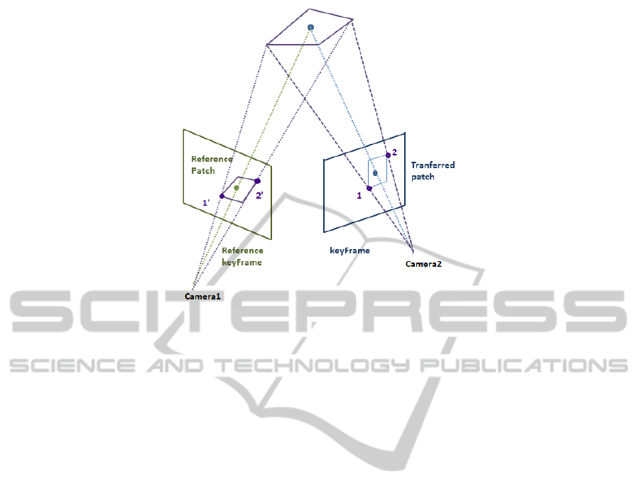
Figure 2: Transfer process: back-projection of two points from the Transferred patch onto the Reference keyFrame using a
plane associated to a 3D point.
two images, where a perfect match will be 1 and
a perfect mismatch will be −1. WaPT algorithm
looks for the highest similarity between Reference
and Transferred patches. So, the value of the cross-
correlation coefficient has to be as high as possible.
However, notice that this value is used in a minimiza-
tion process. For this reason the objective function
shown in equation (6) is used to evaluate the differ-
ence between patches, being crossCorrelation
i
the
normalized cross-correlation coefficient of the patch
applied in frame i, and α,β the two angles used in the
parametrization of a normal.
min(α,β)
∑
i
(1 − crossCorrelation
i
(α,β)) (6)
3.2 Tracking Stage
As in all tracking processes the main goal of this one
is to obtain the camera extrinsic parameters for each
input frame. In this case the input data used for this
purpose is:
1. ReferenceImage set: A set of images and their
extrinsic parameters. They are the Reference
keyFrames. Recall that a Reference keyFrame is
where a 3D point was visible the first time in the
3D Reconstruction stage.
2. PointCloud: a set with all the 3D points that build
a 3D reconstruction of the environment and their
normals. This set was obtained in the 3D Recon-
struction stage. Each 3D point stores the index
of its Reference keyFrame in the ReferenceImage
set.
The goal is to find the projections of the 3D points
in the current image in order to localise the image.
With this purpose, n points from the PointCloud are
randomly chosen as features for the current image.
Through empiric processes, n = 50 has been chosen
for the experiments presented in this paper. These
points are projected onto the current frame. As it is
assumed that the shift between frames is small the ex-
trinsic parameters of the previous frame are used.
An adjustment has to be done in order to obtain the
position of the 3D points in the current image more
accurately. For each approximated projection of a 3D
point we define a patch. Then, two main steps are
performed to make the adjustment correctly:
1. Transfer the patch from the current image to the
Reference keyFrame of the 3D point. In this way,
a Reference patch is obtained.
2. A search process is performed, i.e. look for the
most similar patch to the Reference patch within
the current frame (similarity measurement).
3.2.1 Patch Transfer
The patch transfer is done using the same process as in
the 3D Reconstruction stage. Firstly, the projection of
the 3D point on the current image is used as the center
of the Transferred patch. Using the normal of the 3D
point the plane is obtained. Then, using this plane
the back-projection for each Transferred patch pixel is
done. The intensity of the pixel in the Reference patch
is obtained using bilinear intensity interpolation. In
this way, the image of the Reference patch is obtained.
WaPT-SurfaceNormalEstimationforImprovedTemplateMatchinginVisualTracking
499

3.2.2 Find Adjusted Projected Point
The goal of this step is to find the patch in the cur-
rent image with the highest similarity to the Reference
patch. With this purpose the cross-correlation coeffi-
cient is applied into an established search area. The
search area is a fixed size window W within the cur-
rent image. The projection of the 3D point is its cen-
ter. Experimentally we found that a 128 × 128 search
area gives good results in 720 ×480 images.
In order to achieve more accuracy in the search
process a three level pyramidal reduction is applied.
In this way:
• The three level reduction of W is calculated ob-
taining W
L0
, W
L1
and W
L2
where W = W
L0
.
• I is the original image, i.e the current image.
• In addition, a three level pyramidal reduction is
also calculated for the Reference patch R obtain-
ing R
L0
, R
L1
and R
L2
where R = R
L0
.
Notice that R
L0
, R
L1
and R
L2
are the same im-
age with different resolutions. In order to get robust-
ness against noise the patches that will be used in the
search process are fixed size regions placed in the cen-
ter of R
L0
, R
L1
and R
L2
. Through empiric processes,
8 × 8 regions have been chosen for the experiments
presented in this paper.
Once the pyramidal levels are defined an iter-
ative process is run. In this iterative process the
match uses firstly the lowest pyramidal levels (W
L2
and R
L2
).Then, the result is propagated to the higher
levels (seen Figure 3).
Figure 3: Iterative process where the similarity of the refer-
ence patches in different pyramidal levels is calculated. The
propagation of the adjusted feature from the lowest pyrami-
dal level to the current image can be seen as a result of the
process.
So, firstly R
L2
is found in W
L2
using the cross-
correlation coefficient and the 8 × 8 region places in
the center of R
L2
. The function returns a position in
W
L2
of the region with the highest similarity to R
L2
.
This position is propagated to the next level, i.e W
L1
.
The search area of W
L1
is redefined taking into ac-
count the position calculated in the previous step, ob-
taining W
L1
0
, which is smaller than W
L1
. The pro-
cesses are repeated and R
L1
is found in W
L1
0
.
This iteration process is repeated until the position
is propagated to the final level, W
L0
, and finally to the
original image I. In Figure 3 the propagation of the
point from different levels can be seen.
This process is done for the n points, obtaining a
set with n features that will be used to find the extrin-
sic parameters of the current camera.
4 EXPERIMENTAL RESULTS
This section evaluates the performance and precision
of the proposed algorithm. To measure the accuracy
of the algorithm, the similarity between the Reference
patch and the current patch is measured. The results
of our algorithm are compared to the approach em-
ployed by MonoSLAM (Davison et al., 2007), which
assumes that the orientation of the 3D points always
faces the camera.
With this purpose, an indoor video sequence was
recorded where a camera motion around the same
work place is visualized. The video sequence is built
by approximately 70 frames with 720 × 480 resolu-
tion.
As mentioned previously, in order to evaluate the
WaPT algorithm the similarity between patches is cal-
culated. The normalized cross-correlation coefficient
is used for this purpose. The value ranges between
[−1,1], where 1 indicates that the patches are the
same and −1 perfect mismatch.
In the first experiment, the similarity of the Ref-
erence patch and the current patch is calculated for
n = 50 points. The average of the normalized cross-
correlation coefficient of all the points for each frame
is calculated. Figure 4 shows the evolution of these
averages during the video sequence: the WaPT al-
gorithm is represented with a red line whereas the
approach used by MonoSLAM is represented with a
blue line.
The average cross-correlation coefficient value for
WaPT algorithm is 0.639 and in the case of the ap-
proach used by MonoSLAM algorithm is 0.574, i.e
the similarity of the patches is higher with the WaPT
algorithm.
On the other hand, for each frame the median and
the quartiles of the cross-correlation coefficient val-
ues are calculated. These statistics are used to mea-
sure the stability of both algorithms. Figure 5 shows
the box-plots for the first 10 frames for the WaPT
algorithm and Figure 6 depicts the same informa-
tion for the approach sued by MonoSLAM algorithm.
With the aim of making the comparison visually sim-
VISAPP2015-InternationalConferenceonComputerVisionTheoryandApplications
500
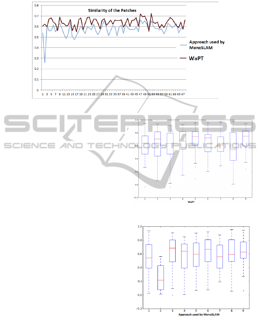
Figure 4: Evolution of the cross-correlation coefficient average values.
pler, only the first 10 frames are provided. These 10
frames are representative of the performance of the
algorithms.
4.1 Discussion
The first discussion point is the difference between
the average normalized cross-correlation coefficient
values appreciated in Figure 4. As it can be seen in
the figure, the WaPT algorithm obtains higher cross-
correlation coefficient values during the video se-
quence. These values define the similarity between
images, and have to be as close as possible to 1.
Therefore, applying WaPT algorithm the template
matching process is more accurate due to the similar-
ity of the patches, i.e. WaPT algorithm obtains more
similar patches than approach used by MonoSLAM.
Furthermore, the average of cross-correlation co-
efficient values in both algorithms confirms that state-
ment. The average value for WaPT algorithm (0.639)
is 11% higher than the value obtained for the ap-
proach used by MonoSLAM (0.574). It means that
taking into account that similarity is measured in
range [−1, 1], WaPT lacks a 18% to achieve a perfect
match while approach used by MonoSLAM lacks a
29%.
The graphics shown in Figures 5 and 6 repre-
sent the distribution of a continuous variable (cross-
correlation coefficient) for both algorithms respec-
tively. The 3rd quartiles in the WaPT algorithm
are higher than in the case of approach used by
MonoSLAM.
Regarding the median values, the same trend is
observed. The median values in WaPT algorithm are
higher than in approach used by MonoSLAM. As a
general trend, it is appreciated that the WaPT algo-
rithm gets more similar patches than the approach
Figure 5: Box-plots of the cross-correlation coefficient val-
ues in the first 10 frames. WaPT algorithm.
Figure 6: Box-plots of the cross-correlation coefficient val-
ues in the first 10 frames. Approach used by MonoSLAM
algorithm.
used by MonoSLAM.
The box-plots graphics demonstrate it; the 3rd
quartiles, the median values and even the minimum
WaPT-SurfaceNormalEstimationforImprovedTemplateMatchinginVisualTracking
501

values are higher in the case of WaPT.
All exposed data confirms that, in this test, the
WaPT algorithm improves the accuracy in the tem-
plate matching process, getting consequently more
accurate feature positions. In autonomous navigation
systems the tracking process has to be done in large
environments where the data from sensors help to im-
prove the tracking process. So, matching improve-
ments are not critical.
Nevertheless, in augmented reality applications,
the accuracy is very important to visualize the vir-
tual elements correctly, that is, drift and jitter must
be reduced as much as possible. In augmented reality
applications this contribution might provide a valu-
able improvement. It is more accurately than template
matching algorithms used in traditional methods.
5 CONCLUSIONS AND FUTURE
WORK
The work presented in this paper proposes a new in-
ternal representation of the environment for marker-
less tracking. Besides the point cloud, a normal vector
for each point is also stored.
In the 3D reconstruction process, not only the 3D
points of the environment are calculated. A minimiza-
tion process is also run in order to estimate the best
normal for each point.
In the tracking process these normals are used to
obtain an improved warped template in order to obtain
a more precise matching.
Perspective deformations are reduced when tem-
plate matching techniques and patches as features are
used.
The results obtained in Section 4 are a first vali-
dation. In this validation, the similarity of the patches
are calculated in order to know the matching process
precision. The results have been favourable to WaPT,
proving its higher accuracy. This approach provides
more precision than traditional methods, which as-
sume that the points are facing the camera.
When more experiments confirm the results pro-
vided by this paper, new research should be done in
order to find methods that accelerate the reconstruc-
tion process for surface normals. One possible ap-
proach could be to start assuming that all surfaces
face the camera as (Davison et al., 2007) and, on-line,
perform a progressive improvement. These normals
might be also useful for surface illumination com-
pensation when comparing images taken in different
lighting conditions.
As future work more validations are planed. Se-
quences with different perspectives, where points do
not face the camera, will be used. In this kind of se-
quences, the traditional methods should be even more
compromised.
In WaPT, the Reference patch is located in the
Reference keyFrame, which is the keyFrame where
the point was first seen. In order to improve more the
precision and the patch similarities, it is planed to use
as the Reference keyframe the one where the point is
visible and it is more similar to the current image.
ACKNOWLEDGEMENTS
Work partially funded by the Spanish Ministry of
Economy and Competitiveness. Project ELAS-
TRACK (TIN2012-33879).
REFERENCES
Alahi, A., Ortiz, R., and Vandergheynst, P. (2012). Freak:
Fast retina keypoint. In Computer Vision and Pat-
tern Recognition (CVPR), 2012 IEEE Conference on,
pages 510–517. Ieee.
Barron, J. L., Fleet, D. J., and Beauchemin, S. S. (1994).
Performance of optical flow techniques. 12:43–77.
Bay, H., Tuytelaars, T., and Van Gool, L. (2006). Surf:
Speeded up robust features. In Computer Vision–
ECCV 2006, pages 404–417. Springer.
Davison, A. J. (2003). Real-time simultaneous localisa-
tion and mapping with a single camera. In Computer
Vision, 2003. Proceedings. Ninth IEEE International
Conference on, pages 1403–1410. IEEE.
Davison, A. J., Reid, I. D., Molton, N. D., and Stasse, O.
(2007). Monoslam: Real-time single camera slam.
In Pattern Analysis and Machine Intelligence, IEEE
Transactions on, volume 29, pages 1052–1067. IEEE.
Dellaert, F., Seitz, S. M., Thorpe, C. E., and Thrun, S.
(2000). Structure from motion without correspon-
dence. In Computer Vision and Pattern Recognition,
2000. Proceedings. IEEE Conference on, volume 2,
pages 557–564. IEEE.
Furukawa, Y. and Ponce, J. (2010). Accurate, dense, and
robust multiview stereopsis. 32(8):1362–1376.
Hartley, R. and Zisserman, A. (2003). Multiple view geom-
etry in computer vision. Cambridge university press.
Klein, G. and Murray, D. (2007). Parallel tracking and map-
ping for small ar workspaces. In Mixed and Aug-
mented Reality, 2007. ISMAR 2007. 6th IEEE and
ACM International Symposium on, pages 225–234.
IEEE.
Lowe, D. G. (2004). Distinctive image features from scale-
invariant keypoints. 60:91–110.
Molton, N., Davison, A. J., and Reid, I. (2004). Locally pla-
nar patch features for real-time structure from motion.
In BMVC, pages 1–10.
VISAPP2015-InternationalConferenceonComputerVisionTheoryandApplications
502

Mor
´
e, J. J. (1978). The levenberg-marquardt algorithm: im-
plementation and theory. In Numerical analysis, pages
105–116. Springer.
Szeliski, R. (2010). Computer vision: algorithms and ap-
plications. Springer.
Triggs, B., McLauchlan, P. F., Hartley, R. I., and Fitzgibbon,
A. W. (2000). Bundle adjustmenta modern synthesis.
In Vision algorithms: theory and practice, pages 298–
372. Springer.
Watman, C., Austin, D., Barnes, N., Overett, G., and
Thompson, S. (2004). Fast sum of absolute differ-
ences visual landmark detector. In Robotics and Au-
tomation, 2004. Proceedings. ICRA’04. 2004 IEEE
International Conference on, volume 5, pages 4827–
4832. IEEE.
WaPT-SurfaceNormalEstimationforImprovedTemplateMatchinginVisualTracking
503
