
Illumination Estimation and Relighting using an RGB-D Camera
Yohei Ogura, Takuya Ikeda, Francois de Sorbier and Hideo Saito
Graduate School of Science and Technology, Keio University,
3-14-1, Hiyoshi, Kohoku, Yokohama, Kanagawa, 223-0061, Japan
Keywords:
Illumination Estimation, Relighting, RGB-D Camera.
Abstract:
In this paper, we propose a relighting system combined with an illumination estimation method using RGB-
D camera. Relighting techniques can achieve the photometric registration of composite images. They often
need illumination environments of the scene which include a target object and the background scene. Some
relighting methods obtain the illumination environments beforehand. In this case, they cannot be used under
the unknown dynamic illumination environment. Some on-line illumination estimation methods need light
probes which can be invade the scene geometry. In our method, the illumination environment is estimated
from pixel intensity, normal map and surface reflectance based on inverse rendering in on-line processing.
The normal map of the arbitrary object which is used in the illumination estimation part and the relighting part
is calculated from the denoised depth image on each frame. Relighting is achieved by calculating the ratio for
the estimated Illumination environment of the each scene. Thus our implementation can be used for dynamic
illumination or a dynamic object.
1 INTRODUCTION
Relighting technique is to change the target object’s
lighting and shadowing to fit another scene which
have different illumination environment. Photomet-
ric registration is one of the important factor of com-
posite images and should be achieved to make them
more realistic. If not, we may feel that something
is wrong. Users can change the illumination envi-
ronment to the object like rendering computer graph-
ics(CG) objects in augmented reality(AR) by using
the relighting technique. Therefore, we consider that
it can be applied for the entertainment experience. For
example, users can see how they look like at a place
where they have never gone and that illumination is
different from that of current place.
Relighting technique generally requires the shape
of the object, the surface reflectance and the illumina-
tion environment of the scene which includes target
object and background scene. Each properties must
be obtained before the relighting process. There are
some relighting research with off-line processing or
on-line processing with known geometry owing to the
difficulty of exacting the object’s shape and the sur-
face reflectance. Therefore, these methods generally
handle a single image or a static object in a movie.
Not only object’s shape and surface reflectance, but
also illumination environment is indispensable to re-
lighting. Illumination estimation has been a topic of
the computer vision field and there are many types
of methods. Off-line illumination estimation cannot
adapt to the dynamic illumination scene which chang-
ing pattern is unknown. Being interested in on-line
relighting in this paper, we focus on on-line illumina-
tion estimation. Illumination environment can be ob-
tained from light probes such as a mirror ball which
is put in the scene or fish eye lens camera. However,
these light probes can cause invasion of geometry or
we have to set another extra camera with fisheye lens.
In this paper, we propose a new relighting ap-
proach which is combined with an illumination es-
timation method. The properties for the illumina-
tion estimation and the relighting are obtained from
a RGB color image and a depth image from an RGB-
D camera. Our goal is to relight an unknown shape
object under the unknown illumination environment
and to realize photometric registration on composite
images. Therefore, object’s shape and illumination
environment should be obtained before the relighting
process.
Normal map significantly affects the illumination
estimation and relighting result. Denoising input
depth image and normal estimation method proposed
by Holzer et al. are helpful to get a good quality
normal map (Holzer et al., 2012). Illumination envi-
305
Ogura Y., Ikeda T., de Sorbier F. and Saito H..
Illumination Estimation and Relighting using an RGB-D Camera.
DOI: 10.5220/0005295403050312
In Proceedings of the 10th International Conference on Computer Vision Theory and Applications (VISAPP-2015), pages 305-312
ISBN: 978-989-758-090-1
Copyright
c
2015 SCITEPRESS (Science and Technology Publications, Lda.)

ronment is estimated on-line based on inverse render-
ing on each frame. We don’t use light probes or fish
eye lens for on-line illumination estimation section,
so that our method can be used under the dynamically
changing illumination. This process is performed on
the scene with target object to be relit, and the scene
to be background. These estimated data are used in
relighting section. Relighting the object is performed
with two estimated illumination data and normal map
of the target object. Finally, the relit object is super-
posed into the background image and a composite im-
age with photometric registration is generated.
2 PREVIOUS WORK
Our goal is to realize the photometric registration for
composite images by relighting, which is combined
with illumination estimation. There are few works
which combine illumination estimation and relight-
ing. So, we discuss previous works of illumination
estimation and relighting individually in this section.
2.1 Illumination Estimation
There are some previous work for the illumination es-
timation with different approaches. Nowrouzezahrai
et al. proposed a method which obtains the illumina-
tion environment from mirror ball (Nowrouzezahrai
et al., 2011). Mirror ball can reflect the surrounding
illumination environment. They set the mirror ball on
known position relative to a AR marker and capture it
to obtain the illumination environment. This approach
causes the restriction of geometry. We have to capture
a mirror ball in the real scene when the illumination
or camera pose has been changed.
Another approach for the illumination estimation
is using cast shadow. Panagopoulos et al. proposed
a estimation method using cast shadow on the ground
and rough 3D geometry (Panagopoulos et al., 2011).
This method can exclude mirror balls, but, of course,
the cast shadow must be in the image. That can be
another scene restriction.
Gruber et al. estimated a illumination environ-
ment by using 3D reconstruction (Gruber et al., 2011).
The main idea is based on inverse rendering, so they
don’t use light probes, such as mirro balls or a fish
eye lens. They estimate the illumination environment
from a normal map, pixel intensity and surface re-
flectance. The normal map of the scene is obtained
from 3D reconstruction data. The restriction of this
method is that light source color must be white. Us-
ing 3D reconstruction, users have to make an effort
to scan the object before the illumination estimation
process.
2.2 Relighting
Zhen et al. proposed a relighting technique for hu-
man faces (Zhen et al., 2003). This builds on a ratio-
image based technique. The advantage of this method
is that it requires only one input face images, but this
technique can handle stationary human face images,
and the normal map is estimated from generic human
face model. Aldrian et al. proposed a face relighting
method considering not only diffuse component but
also specular component so that more natural relight-
ing results are obtained (Aldrian and Smith, 2011).
Debevec et al. proposed a method to acquire the
reflectance field of a object with Light Stage (Debevec
et al., 2000). They take 2048 images under the differ-
ent light conditions and estimate the reflectance func-
tion of the object. Not only they can get relighting
result, but also they can change the viewpoint from
the reflectance function. Wenger et al. implement
newer Light Stage and high speed cameras to take
more larger number of images (Wenger et al., 2005).
Using their Light Stage and high speed cameras, their
method can be applied to the moving object. These
technique can obtain high quality relighting results
thanks to their special recording equipment.
3 PROPOSED SYSTEM
The purpose of our method is illumination estimation
and relighting to realize the photometric registration
for composite images. Our system consists from two
parts: illumination estimation part and relighting part.
Input data are color image and depth image of two
scenes. One is the scene which contain the object to
be relit, and the other is background scene. The illu-
mination Estimation part builds on the work by Gru-
ber et al.(Gruber et al., 2011). In this paper, we don’t
take account of geometric registration.
In advance, surface reflectance is estimated un-
der known illumination environment off-line. This is
done only once. Next, we obtain normal map from a
depth image. This normal map is also used in relight-
ing part. Illumination environment is estimated from
pixel intensity, normal map and surface reflectance
based on inverse rendering, without light probes.
After estimating two illumination environment,
we relight the object to fit the illumination to the back-
ground scene. Relighting process is done with pixel
intensity, normal map and two estimated illumination
VISAPP2015-InternationalConferenceonComputerVisionTheoryandApplications
306
environment. We calculate the ratio of the inverse ren-
dering equation of the both scene to get the relighting
result. Finally, the target object is superposed to the
composite image to get the final result.
3.1 Normal Map Estimation
The accuracy of the normal map is very important for
illumination estimation and relighting. Simply calcu-
lating the normal map from depth images, we may not
get a good result because of noises on depth images.
Before the normal map estimation, we apply bilateral
filter and temporal filter to depth images. The bilat-
eral filtered depth map D
b
is obtained from raw depth
mapD by using following equation:
D
b
(u) =
1
k
′
(u)
∑
v∈Ω
g
′
g
s
′
(u, v)g
d
(D(u), D(v))D(v)
(1)
Note that g
s
′
(u, v) is the spatial Gaussian weight
and g
d
(I(u), I(v))D is the color similarity Gaussian
weight. k
′
(u) is a normalize factor and Ω
g
′
is a square
window whose center is u. After applying bilateral
filter, we also apply the temporal filter (Matsumoto
et al., 2014). In our method, a current depth image
is denoised by using a current frame and a previous
frame.
D
t f
(u) =
(D
b
(u)(w+ 1) + D
b−1
(u)w)
2w+ 1
(2)
w is a constant weight term. After denoising the depth
image, we can obtain a vertex map corresponding to a
camera coordinate since we assume that the camera’s
intrinsic parameters are known. We estimate the nor-
mal map based on the work by Holzer et al. (Holzer
et al., 2012). This method can obtain the smooth nor-
mal map. However, this method cannot estimate the
normal vector where the difference of the depth value
is too large such as the boundary of the object. On
these areas, we obtain the normal vector by calculat-
ing a cross product of two vectors from the neighbor
points. Normal vector N (u) at a point u = (u, v)
N (u) = (V(u+1, v)−V(u, v))×(V(u, v+1)−V(u, v))
(3)
V(u, v) is a vertex map corresponding to a camera co-
ordinate. Combining these two method, the normal
map is obtained.
3.2 Spherical Harmonics Lighting
The purpose of this section is to explain the illumi-
nation estimation theory. Relationship between color
pixel intensity, normal vector and surface reflectance
is presented by Ramamoorthi et al. (Ramamoorthi
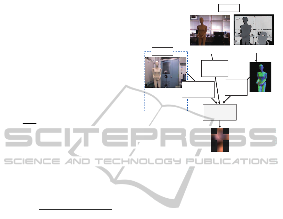
Color Image
Depth Image
Illuminaon
Environment
Surface
Reflectance
Esmaon
Normal
Map
Illuminaon
Esmaon
Offline
Online
Pixel
Intensity
Surface
Reflectance
Normal
Vector
Figure 1: Illumination Estimation Flow.
and Hanrahan, 2001b). We assume that the light
source is distant and objects in the scene have lam-
bertian surfaces.
The irradiance E(x) observed at a point x is given
by an integral on the distant sphere Ω
E(x) =
Z
Ω
L(ω)max((ω · n(x)), 0)dω (4)
L(ω) is incoming light intensity along the direction
vector ω = (θ, ϕ) and n(x) is normal vector at a point
x. max((ω · n(x)), 0) shows a dot product of a nor-
mal vector and incoming light direction. This means
that if a normal vector and incoming light vector has
the same direction, the light from that direction is
fully considered, but if the angle of these two vec-
tor is more than 90 degree, we don’t take care of the
light from that direction.
We are interested in estimating the incoming light
L(ω). It takes too much cost to estimate the illumina-
tion as a aggregate of point sources. The illumination
is approximated with Spherical Harmonics(SH) to re-
duce the calculating cost. The illumination is shown
with SH basis function y and the coefficients c The
equation 4 will be represented in the following equa-
tion.
E(x) =
∞
∑
l=0
l
∑
m=−l
A
l
(θ)L
l,m
Y
l,m
(ω) (5)
l denotes the SH band. There are 2l + 1 functions
in band l, and m denotes the index in a band. A
l
(θ)
IlluminationEstimationandRelightingusinganRGB-DCamera
307
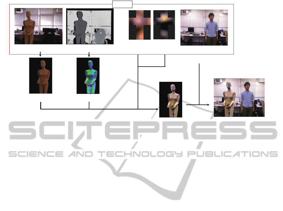
Depth Image(Src)
Normal Map
Color Image(Src)
Segmented Image
Illumina•on
(Src)
Illumina•on
(Dst)
Color Image(Dst)
Output Image
Religh•ng Result
Input
Figure 2: Relighting Flow.
is the SH projection of max((ω · n(x)), 0). It is ob-
tained by rotating the standard cosine term A
std
l
which
is equal to A
l
(0) (Nowrouzezahrai et al., 2012). Y
l,m
is the basis function of SH and L
l,m
is the coefficient
of each SH basis function. In this paper, we consider
equation(5) in RGB color space to apply it to color il-
lumination estimation. The color pixel intensity I(x)
is written as
I(x) = R
d
∞
∑
l=0
l
∑
m=−l
A
l
(θ)L
l,m
Y
l,m
(ω) (6)
R
d
represents surface reflectance. Since we consider
lambertian surface uniformly reflects the incoming
light to all direction, R
d
is set to constant values cor-
responds to RGB color space.
3.3 Surface Reflectance Estimation
In our method, we estimate the surface reflectance in
advance. Only surface reflectance estimation is off-
line process. Here, we consider that the illumination
environment is known only in this section since the
estimation of the illumination environment and sur-
face reflectance at the same time is ill-posed prob-
lem. Surface reflectance is calculated from illumina-
tion environment data, pixel intensity and normal map
from selected sample points. We assume that the re-
gion with the same color and the same material have
uniform reflectance value. Thus, we estimate the sur-
face reflectance of one arbitrary region. The pixel in-
tensity and the normal vector which will be used in
the illumination estimation are selected from that re-
gion. Considering color illumination estimation, sur-
face reflectance has 3 values corresponding to RGB
color space. We select sample points and make mul-
tiple equation(6). Surface reflectance is finally calcu-
lated from average value of each sample points.
3.4 Illumination Estimation
Since we obtained pixel intensity, normal map and
surface reflectance, we can estimate the illumination
environment of the scene. Illumination is estimated
by using equation(6). As shown in Fig.1, this pro-
cess is done with pixel intensity, normal vector and
surface reflectance. These properties are obtained
from the sample points which selected from the re-
gion where the reflectance is estimated. We can get
multiple equation(6) so we can estimate L(ω) by us-
ing liner least square method. Illumination environ-
ments of both two input scenes are estimated and they
will be used in relighting part.
3.5 Selecting Sample Points
In the illumination estimation part, pixel intensity and
normal vector to be used are obtained from sample
points. We select these sample points from the largest
segmented area by kmeans clustering on first frame.
Clustering is applied to color phase because both a
bright area and a dark area on the same material(same
color) are needed for illumination estimation. On
second frame and after, we check all sample points
whether they are in the segmented region. If some
of them are out of region, these sample points are
re-selected from segmented region on corresponding
frame.
VISAPP2015-InternationalConferenceonComputerVisionTheoryandApplications
308

3.6 Relighting
In this part, we explain the relighting method. At first,
we define the name of each scene. Src is the scene
which has the object to be relit and Dst is the scene
to be the background image of the relit object. Fig.2
shows the flow of relighting section. The object to be
relit in Src scene is segmented by thresholding depth
value. We can calculate the pixel intensity of the re-
lit object fitting to Dst illumination environment by
the ratio of equation(6) (Zhen et al., 2003). Thus re-
lighting result is obtained from pixel intensity, normal
map which is the same one as estimated in illumina-
tion estimation part, and illumination environment of
Src and Dst scenes.
I
Dst
(x) = I
Src
(x)
∑
2
l=0
∑
l
m=−l
A
l
(θ)L
Dst
l,m
Y
l,m
(ω)
∑
2
l=0
∑
l
m=−l
A
l
(θ)L
Src
l,m
Y
l,m
(ω)
(7)
I
Dst
(x) is a pixel intensity of the relit object and
I
Src
(x) is an original pixel intensity of the object to
be relit. Note that surface reflectance R
d
is canceled
by computing the ratio in this equation. Therefore, we
don’t have to estimate all surface reflectance in Src
scene. We can get the final result image by superpos-
ing the relit target object on Dst background image.
4 IMPLEMENTATION
The quality of illumination estimation depends on
the number of spherical harmonics coefficients. The
more SH coefficients are increased, the more detailed
illumination environment is obtained, but also in-
crease the processing cost. Ramamoorthi and Han-
rahan showed that 9 SH coefficients are enough to
approximate the illumination when assuming Lam-
bertian surface (Ramamoorthi and Hanrahan, 2001a).
Based on this work, we obtain the illumination en-
vironment by estimating 9 SH coefficients. We use
Kinect(Microsoft Corporation, 2012) as the RGB-D
camera and assume that camera intrinsic parameters
for converting depth image to vertex map is known.
5 EXPERIMENTS
In this section, experiments were performed under
different illumination condition or targetobject to ver-
ify the performance of our system.
5.1 Experiment Condition
We estimate the illumination and relight under 2 types
of patterns. Pattern 1 consists from Src having dy-
namic illumination and static object and Dst having
static illumination and static object (Fig. 3). Pattern
2 consists from Src having static illumination and dy-
namic object and the same Dst as Pattern 1 (Fig. 4).
The pattern 1’s illumination of Src is mainly a spot
light. We light a target object(a mannequin) with a
spot light which illuminate a ceiling of the room as a
indirect lighting. It moves from the left side through
the upper side to the right side of the camera. The
illumination of Src on Pattern 2 consists from lights
on the ceiling, but the target twists his body. The tar-
get of Dst is lit by the light from the rooms and flu-
orescent lamps in the corridor, but there is no lamps
just right above the target. The target to be relit is
the mannequin in Pattern 1 and the person wearing
blue shirt in Pattern 2. The person in Dst scene is for
obtaining properties of illumination estimation. Esti-
mated illumination is shown as a cube map (Debevec,
2008). It’s a development view of a cube to which
the illumination is projected. Cube map coordinate is
corresponding to camera coordinate.
(a) Src scene (b) Dst scene
Figure 3: Src and Dst scenes of Pattern 1.
(a) Src scene (b) Dst scene
Figure 4: Src and Dst scenes of Pattern 2.
5.2 Experiment Result: Pattern 1
First, we discuss the result of Pattern 1. The man-
nequin is lit indirectly by a spot light. The color
of the mannequin is beige but it is observed as am-
ber because the light has amber color a little. Mean-
while in Dst scene, the light color is white. There-
fore, color illumination estimation is important in this
case. Properties for the illumination estimation are
IlluminationEstimationandRelightingusinganRGB-DCamera
309
1
st
frame 200
th
frame 400
th
frame
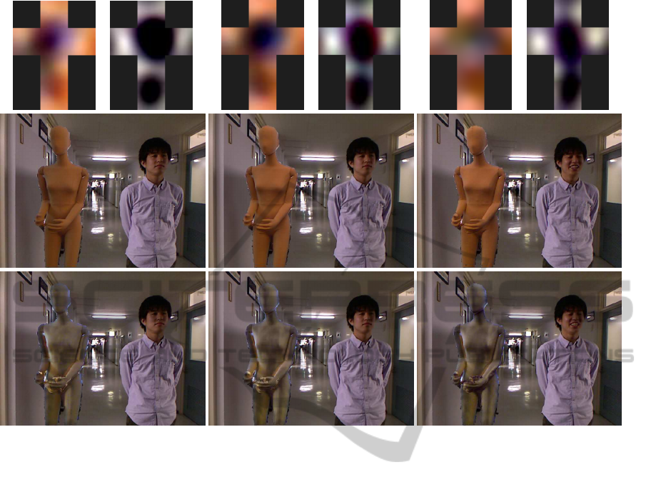
Figure 5: Relighting results of Pattern 1. Each caption shows frame number. First column shows estimated illumination
environment. Upper left side on each frame is Src illumination and upper right side is Dst illumination. Second column shows
composite images without relighting. Third column show relighting result with estimated illumination data.
obtained from sample points which are randomly se-
lected from segmented regions. They are selected
from Mannequin body on Src scene, and from light
purple shirt what the person wears on Dst scene.
Result images are shown in Fig. 5. Focusing on
illumination estimation, the results of Src shows that
we could accurately estimate the incoming light di-
rection: left side on 1st frame, upper side on 200th
frame, and right side on 400th frame. The results
of Dst is mainly highlighted around x axis on cube
map images on each frame. The illumination of Dst
is static, so the illumination environment can be esti-
mated from the clothes observed in images.
With these estimated illumination data, the man-
nequin is relit fitting to Dst illumination environment.
We could change the shadowing on the mannequin
even incoming light direction of Dst is opposite to that
of Src. However, due to object segmentation, there
is a few confusing area around the boundary of the
object. We need to improve the object segmentation
method to get more accurate result.
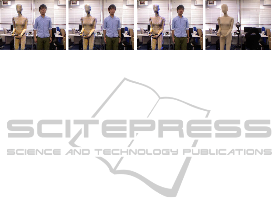
5.3 Experiment Result: Pattern 2
Next, we discuss the result of Pattern 2. The target
person is not static but moving in Src scene. Unlike
pattern 1, the light source is fluorescent lamps so it
has no specific color and incoming light is from up-
per side of the target. Dst scene is the same one as
Pattern 1.
Result images are shown in Fig. 6. The illumina-
tion in Src is mainly from lamps on the ceiling. Fo-
cusing on estimated illumination of Src, around y+
axis of cube map images is highlighted. Obtaining
the normal map of the target object on each frame, we
could estimate the illumination environment even the
target is moving.
Comparing to no relit image, the target in relight-
ing result image with our method is naturally super-
posed to the background image. Brightness of front
side of the blue shirt changes in proportion to the
angle of the target person. We could also relight
the moving target by obtaining target shape on each
frame. Non static target like this pattern can confuse
the illumination estimation. That process is sensitive
VISAPP2015-InternationalConferenceonComputerVisionTheoryandApplications
310
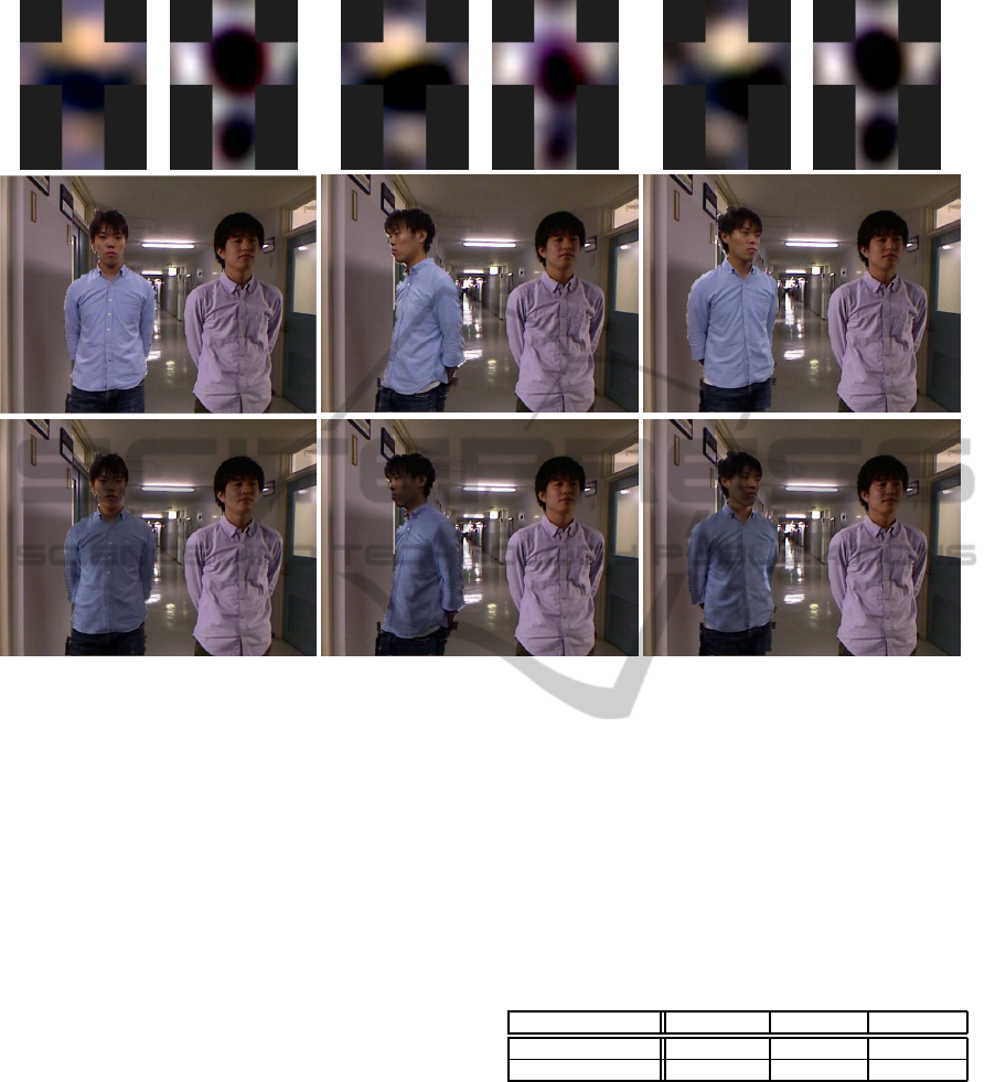
1
st
frame 150
th
frame 260
th
frame
Figure 6: Relighting results of Pattern 2. Each caption shows frame number. First column shows estimated illumination
environment. Upper left side on each frame is Src illumination and upper right side is Dst illumination. Second column shows
composite images without relighting. Third column show relighting result with estimated illumination data.
to noise of the normal map, so noise reduction of a
depth image and a normal map is very helpful for
steady illumination estimation.
5.4 Comparing with Ground Truth
To evaluate our method, we compare the results with
ground truth data. We calculate root mean square er-
ror value between relit target and ground truth. The
ground truth image is captured with the same position
with Src data, but different illumination condition by
changing the lamps on the ceiling. Root mean square
error values are shown in Table 1 with the case of the
result without relighting for comparison. Images are
shown in Fig. 7.
Each error value with relighting is reduced com-
paring to the result without relighting. Src is the same
as Pattern 1 so the illumination is changing dynam-
ically. Error values with relighting varies less than
that without relighting. From this result, we can say
that our method could estimate the dynamic illumi-
nation accurately. The accuracy of normal map is
very important in our system. Illumination estima-
tion needs more normal vector with various direc-
tion, but the accuracy of normal vectors of the area
around the boundary is not good. It is caused by diffi-
culty of estimating the normal vectors which direction
is nearly right-angled to camera and obtaining depth
values around those area.
Table 1: Root Mean Square error value comparing with
Ground Truth(pixel value).
frame: 001 frame:350 frame:700
with relighting 17.04 16.87 19.11
without relighting 25.01 21.46 24.48
5.5 Limitation
Our method can be applied for arbitrary shape objects
and illumination environment. However, we assume
that the object’s surface is Lambertian. Therefore,
it is difficult to apply our method to specular object.
We also consider that the incoming lights are distant.
Therefore, the weak incoming lights may not be esti-
mated accurately. To solve these problems, we need
to improve the lighting model and estimate the object
BRDF.
IlluminationEstimationandRelightingusinganRGB-DCamera
311
(a) frame: 001 (b) frame: 350 (c) frame: 700 (d) Ground Truth
Figure 7: Comparison with Ground Truth.
6 CONCLUSION
In this paper, we proposed a relighting method which
combined with illumination estimation using RGB-D
camera. Before illumination estimation, we denoise
depth images by bilateral filter and temporal filter to
get smooth normal map. Based on inverse rendering,
Illumination environment is estimated from a color
image, normal map from a denoised depth image and
surface reflectance. After that, Relighting process is
done with estimated illumination data. Our method
estimates the illumination on each frame, and also ob-
tain normal map of the target object on each frame.
Therefore, our method can be applied to dynamic illu-
mination or dynamic target. In experiment, we tested
our method on two types of situation. We will im-
proveour method more robust, and also apply to spec-
ular objects.
ACKNOWLEDGEMENTS
This work was partially supported by MEXT/JSPS
Grant-in-Aid for Scientific Research(S) 24220004,
and JST CREST ”Intelligent Information Process-
ing Systems Creating Co-Experience Knowledge and
Wisdom with Human-Machine Harmonious Collabo-
ration”.
REFERENCES
Aldrian, O. and Smith, W. (2011). Inverse rendering with a
morphable model: A multilinear approach. In Pro-
ceedings of the British Machine Vision Conference.
BMVA Press.
Debevec, P. (2008). Rendering synthetic objects into real
scenes: Bridging traditional and image-based graph-
ics with global illumination and high dynamic range
photography. In ACM SIGGRAPH. ACM.
Debevec, P., Hawkins, T., Tchou, C., Duiker, H. P., Sarokin,
W., and Sagar, M. (2000). Acquiring the reflectance
field of a human face. In ACM SIGGRAPH. ACM.
Gruber, L., Richter-Trummer, T., and Schmalstieg, D.
(2011). Real-time photometric registration from ar-
bitrary geometry. In IEEE Int’l Symposium on Mixed
and Augmented Reality. IEEE.
Holzer, S., Rusu, R. B., Dixon, M., Gedikli, S., and Navab,
N. (2012). Adaptive neighborhood selection for real-
time surface normal estimation from organized point
cloud data using integral images. In IEEE/RSJ Int’l
Conference on Intelligent Robots and Systems. IEEE.
Matsumoto, K., Song, C., de Sorbier, F., and Saito, H.
(2014). Joint upsampling and noise reduction for
real-time depth map enhancement. In Proceedings of
IS&T/SPIE Electronic Imaging. SPIE.
Microsoft Corporation (2012). Kinect for Windows. Mi-
crosoft.
Nowrouzezahrai, D., Geiger, S., Mitchell, K., Sumner, R.,
Jarosz, W., and Gross, M. (2011). Light factorization
for mixed-frequency shadows in augmented reality. In
IEEE Int’l Symposium on Mixed and Augmented Re-
ality. IEEE.
Nowrouzezahrai, D., Simari, P., and Fiume, E. (2012).
Sparse zonal harmonic factorization for efficient sh ro-
tation. ACM Transactionson Graphic.
Panagopoulos, A., Wang, C., Samaras, D., and Paragios,
N. (2011). Illumination estimation and cast shadow
detection through a higher-order graphical model. In
IEEE Conference on Computer Vision and Pattern
Recognition. IEEE.
Ramamoorthi, R. and Hanrahan, P. (2001a). An efficient
representation for irradiance environment maps. In
ACM SIGGRAPH. ACM.
Ramamoorthi, R. and Hanrahan, P. (2001b). A signal-
processing framework for inverse rendering. In Pro-
ceedings of the 28th annual conference on Computer
graphics and interactive techniques. ACM.
Wenger, A., Gardner, A., Tchou, C., Unger, J., Hawkins,
T., and Debevec, P. (2005). Performance relighting
and reflectance transformation with time-multiplexed
illumination. ACM Transactions on Graphics.
Zhen, W., Liu, Z., and Huang, T. S. (2003). Face relighting
with radiance environment maps. In IEEE Conference
on Computer Vision and Pattern Recognition. IEEE.
VISAPP2015-InternationalConferenceonComputerVisionTheoryandApplications
312
