
Synthesizing Realistic Shadows with Bumpy Surface and Object Model
Estimated by Shadows in Single Image
Jung-Hsuan Wu
1
and Suguru Saito
1,2
1
Department of Computer Science, Tokyo Institute of Technology, Tokyo, Japan
2
Department of Informance Sciences, Ochanomizu University, Tokyo, Japan
Keywords:
Image-based Modeling, Image-based Rendering.
Abstract:
Shadows play an important role in the human perception of 3D geometry in photographs, and properly syn-
thesized shadows produce a realistic rendering result. Shadows, especially hard shadows, define powerful
constraints between a light source, occluders, and the surfaces onto which shadows are cast. We aim to create
a pseudo 3D scene in which the light produces shadows that are the same as those in the input image by taking
the shadow constraints into account. Our method requires only a few user annotations and an input image,
with the objects and their cast-shadows segmented in advance. The segmentation and the user annotations are
used to create a shadow-free texture and a 3D scene, and users can then interactively edit the image by mov-
ing the objects and changing the lighting. Our system produces realistic shadows in real-time while enabling
interactive editing.
1 INTRODUCTION
Shadow, as one of the most common lighting ef-
fects, is very important in computer graphics, com-
puter vision, image processing, and many other fields.
Shadow provides appropriate cues for reconstructing
the 3D geometry of a scene, and there has been much
research focusing on estimation with shadow.
In general, shadows can be classified into cast-
shadows and self-shadows. A cast-shadow is cast
by a light source, and there is always an object be-
tween the light source and the shadow. The shape
of a cast-shadow is related to the shape of the object
that occludes light rays from the light source, so the
cast-shadow also indicates the shape of the object that
casts it. Much research had focused on estimating,
rendering, and removing cast-shadows in images.
Self-shadow, in contrast, is less frequently dis-
cussed than cast-shadow, although it is also impor-
tant in the human perception of 3D geometry. The
difference between a self-shadow and a cast-shadow
is that, with a self-shadow, the object occluding light
rays from a light source is part of the surface on which
the shadow appears, rather than another object. Self-
shadows are often observed on bumpy surfaces such
as grass or folded clothes.
Our objective in this work is to estimate and re-
cover the 3D geometry of scenes in which the same
shadow as that seen in the input image is cast. We
have developed a method to recover the bumpy sur-
face with the self-shadow on it, and we also propose
a method to estimate the 3D model of object with the
shadow it casts. Our method requires only a single
input image and a small number of user annotations,
and can be applied to images containing hard shad-
ows such as photographs of sunny outdoor scenes or
night scenes illuminated by streetlamps.
2 RELATED WORK
Estimation of Shadows
Wu, Tang, Brown, and Shum (2007) modeled the
cast-shadow using a Gaussian mixture model. Their
method removes the cast-shadow from an image and
then synthesizes it onto another image. Bousseau,
Paris, and Durand (2009) estimated the shading and
self-shadows of objects and separated the image into
shading and albedo components. The user can then
change the textures and a realistic result is synthe-
sized. Both methods extract and allow limited ma-
nipulation of the shadows in an image, but the shape
of the shadows is not changeable because the object
that casts the shadow is not taken into account.
Kee, O’Brien, and Farid (2013) proposed a
35
Wu J. and Saito S..
Synthesizing Realistic Shadows with Bumpy Surface and Object Model Estimated by Shadows in Single Image.
DOI: 10.5220/0005298200350045
In Proceedings of the 10th International Conference on Computer Graphics Theory and Applications (GRAPP-2015), pages 35-45
ISBN: 978-989-758-087-1
Copyright
c
2015 SCITEPRESS (Science and Technology Publications, Lda.)
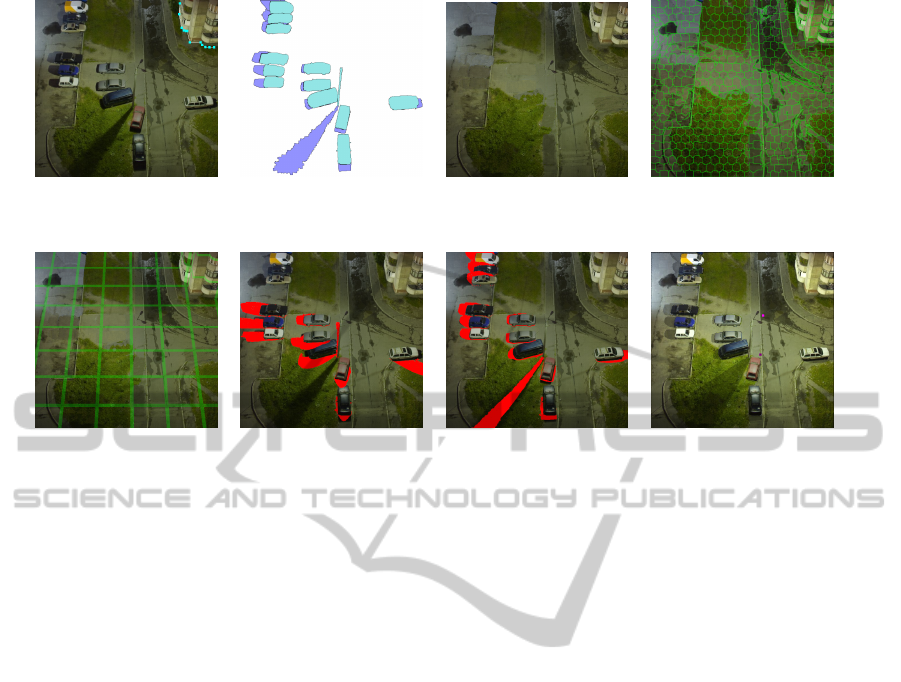
(a) Input image and user- (b) Segmentation of objects (c) The shadow-free texture, (d) Superpixels established
marked edges between and cast-shadows. T, obtained by PatchMatch. by VCells.
ground and wall.
(e) 3D geometry of ground (f) Shadows cast by 3D (g) Shadows cast by (h) Scene synthesized with
and walls. model of objects before optimized 3D model of recovered 3D models.
optimization. objects.
Figure 1: System overview. Our method requires an input image (a) and segmentation of the objects and the cast-shadows
(b). A shadow-free texture (c) is generated by removing cast-shadows and objects using the PatchMatch algorithm. User
annotations, self-shadows, and superpixels (d) are used to reconstruct the 3D geometry of the ground and walls (e), and the
shape of the objects are recovered with their cast-shadows (f)(g). The final result (h) is synthesized with the shadow-free
texture and reconstructed 3D models and the user is able to edit the image by moving the objects and the light source. An
example image synthesized after editing is shown in Figure 6.
method to reconstruct the relationship between
shadow, object, and light source from a single image
with user input. The user specifies the shadow, and
the position of the object that casts the user-specified
shadow is then accurately computed with the recon-
structed relationship. This method aims to determine
the position of the object in an image from its cast-
shadow. Different from this method, we want to gen-
erate a 3D model for the object with its cast-shadow,
so the user is required to specify the object region in
an image.
Shadow Carving
Savarese, Andreetto, Rushmeier, Bernardini, and Per-
ona (2007) built a device to automatically reconstruct
the geometry of an object by self-shadows. In their
method, an object is placed on a rotatable plate and
a camera surrounded by several lights is aimed at the
object. By alternately turning on different lights and
capturing pictures of the object from different views, a
3D model of the object is created by the self-shadows
observed in the image. However, since this method re-
quires images from multiple views and lighting from
different directions, it is difficult to apply it to an or-
dinary single photograph. In contrast, our method es-
timates the shape of an object with a single input im-
age and a small number of user annotations that can
be specified in just minutes.
User-assisted Image-based Modeling
Horry, Anjyo, and Arai (1997) proposed an efficient
method to create a simplified 3D scene with one in-
put image and a small amount of user input. Al-
though this method allows rendering from different
viewpoints in a scene, the scene itself is not editable.
Karsch, Hedau, Forsyth, and Hoiem (2011) presented
a method to estimate the scene and illumination con-
dition in an image, and a realistic result of inserting
synthetic objects into the image is synthesized with
the estimated 3D model and illumination condition.
However, this method also does not support editing
of the scene or the lighting.
The method proposed by Zheng, Chen, Cheng,
Zhou, Hu, and Mitra (2012) allows users to interac-
tively edit the scene. This method effectively extracts
the object by minimizing the error, which is computed
according to the user annotations, and provides an in-
terface for the user to modify the objects. However,
their assumption that the objects are combinations of
cuboids means their method can not be applied to ob-
jects with curved surfaces such as cars or trash cans.
Our method, in contrast, assumes that objects have a
GRAPP2015-InternationalConferenceonComputerGraphicsTheoryandApplications
36

smooth surface but still allows sharp edges, so it can
generate a 3D model for objects of different shapes.
Kholgade, Simon, Efros, and Sheikh (2014) pro-
posed a method to manipulate the 3D object in a sin-
gle image. This method supports full 3D operations,
including translation, rotation, and scaling, but it as-
sumes that the 3D model and the texture of the object
in the image is known. This assumption limits the ap-
plication of their method to objects whose 3D model
is available. With our method, we aim to create a 3D
model with constraints provided by the user and do
not require the original 3D model of the object.
3 ALGORITHM
The appearance of the scene in an image I is deter-
mined by its geometry X, texture T, and light source
L.
I = v(L, X) lam(L,X) T (1)
where v(·) denotes the visibility of light source L at
scene X and lam(·) is the Lambertian cosine function.
Since I is the only known variable in Equation 1, and
because estimating X, T, and L from I is highly ill-
posed, we ask the user to specify the light source L
and to label the background, the object, and its cast-
shadow pixels, as shown in Figure 1(b), in which pix-
els labeled as the object are cyan, shadow-labeled pix-
els are blue, and the background is white. One object
region must have one shadow region. This user input
provides powerful cues to solve X and T. The texture
of the scene, T, is obtained by inpainting the user-
labeled object regions and shadow regions with the
PatchMatch algorithm proposed by Barnes, Shecht-
man, Finkelstein, and Goldman (2009). Figure 1(c)
shows the scene texture T, in which the objects and
their cast-shadows are removed. Typical shadow re-
moval methods, e.g., Wu et al. (2007), can be applied
to generate T, too, but these may require a greater
number of user annotations.
We separate the 3D geometry of the scene into
the ground and walls, denoted as X
S
, and several 3D
models for the objects, denoted as X
i
. The 3D model
X
i
corresponds to the i-th object region, O
i
, labeled
by the user. Different approaches are used to create
X
S
and X
i
.
For X
S
, we assume that the walls are perpendic-
ular to the horizontal ground and that the camera is
at the origin and has no yaw or roll rotation. We
first generate a rough 3D geometry of the ground and
walls, X
0
S
, using the approach proposed by Iizuka,
Kanamori, Mitani, and Fukui (2011). This method
automatically generates 3D geometry for the ground
and walls as well as camera parameters with edges
Figure 2: The bumpy surface derived by using superpixels
(left) and bilateral filter (right).
between the ground and walls marked by the user, as
illustrated in Figure 1(a). The rough 3D geometry X
0
S
is refined to X
S
with self-shadows using the method
presented in Section 3.1.
For X
i
, our method processes one object at a time.
We first generate a rough 3D model for the current
object and then refine the 3D model by the relation-
ships between the light source, the object, and its cast-
shadow using the method presented in Section 3.2.
After deriving X
S
and all X
i
, the final 3D geome-
try X is constructed by inserting all X
i
into X
S
. The
user is allowed to modify X and L by moving the
foreground objects and the light source, and the re-
sulting image is then synthesized by Equation 1. In
our implementation, the shadow mapping algorithm
proposed by Williams (1978) is used to generate the
visibility term v(·) in Equation 1.
3.1 Bumpy Surface Recovery
In general, self-shadows appear at the concaves of a
bumpy surface, while convexes are usually brighter
than the other parts of the surface. Khan, Reinhard,
Fleming, and B
¨
ulthoff (2006) proposed a method to
derive bump heights for the surface by intensity. In
that method, bilateral filter is applied to obtain the
albedo component and the intensity of albedo com-
ponent is then directly used as the bump heights of
the surface. However, if a surface has multiple colors,
this approach tends to separate the surface into mul-
tiple pieces with different altitudes according to the
color (see Figure 14).
We overcame this problem by considering local
texture, which is obtained by superpixels. A super-
pixel is a set of pixels containing pixels of similar
color, and thus we assume that all pixels in a super-
pixel have the same albedo and variation in intensity
mostly caused by lighting. We chose not to use bi-
lateral filter to recover the albedo because it might
slightly blur the edges between different colors, and
produce an uneven surface like the one in Figure 2
(right). The advantage of using superpixels is that
they do not cross the edge between different textures,
SynthesizingRealisticShadowswithBumpySurfaceandObjectModelEstimatedbyShadowsinSingleImage
37
so flat surfaces can be derived even on the edge be-
tween different colors, as shown in Figure 2 (left).
Our method first segments the shadow-free image
T, which is derived by the PatchMatch algorithm, into
superpixels by using the VCell method proposed by
Wang and Wang (2012). The mean color of the pixels
in each superpixel is then used as the albedo of the
pixels in that superpixel. The concaves and convexes
of a bumpy surface often directly relate to the illumi-
nation distribution on the surface, so the bump heights
are derived according to the difference between the
intensity of each pixel and its albedo. Denoting the
bump height as b and the albedo by ρ, we compute
the bump height by
b(x,y) = σ
int
T(x,y)
− int
ρ(x,y)
(2)
where int(·) returns the intensity of the given color
and σ is the constant control, adjustable by the user,
of the bumpiness of the surface. We set σ to 0.01 in
all our experiments.
We derive the normal map, N, of the rough scene
geometry X
0
S
by a cross-product of tangent vectors,
which we denote as U and V.
N(x,y) = U(x,y) × V(x, y) (3)
These U and V tangent vectors are obtained by com-
puting the gradient of X
0
S
along the x- and y-axes of
the image.
U(x,y) = X
0
S
(x,y) − X
0
S
(x − 1, y)
V(x,y) = X
0
S
(x,y) − X
0
S
(x,y − 1)
The 3D geometry of the ground and walls is then
refined with the bump height, b, and the normal map,
N.
X
S
(x,y) = X
0
S
(x,y) + b(x,y)N(x,y) (4)
After deriving X
S
, the normal map N is computed
again with Equation 3 but using the refined 3D geom-
etry X
S
rather than X
0
S
.
3.2 Object Model Creation
Our method creates a 3D model X
i
by generating ver-
tices that correspond to the pixels inside the i-th object
region O
i
labeled by the user, i.e., ∀ pixel p ∈ O
i
, p
corresponds to one x
p
, where x
p
is a vertex of X
i
, and
the inflation method introduced by Johnston (2002) is
applied to determine the initial position of each vertex
x
p
. Denoting the 3D model created by the inflation
method as X
0
i
, it casts a shadow S
0
Oi
, which is cal-
culated by a common shadow mapping with the light
specified by the user. The pixels that are labeled as
’object’ are excluded from the cast-shadow since we
do not know what the shadow looks like behind the
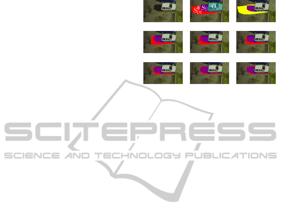
(a) (b) (c)
(d) k = 1. (e) k = 2. (f) k = 3.
(g) k = 10. (h) k = 20. (i) k = 40.
Figure 3: (a) Input image. (b) O
i
(cyan), the i-th object re-
gion labeled by user, S
0
Oi
(red), the shadow cast by initial
3D model X
0
i
, and S
U
(blue), the shadow region labeled
by user. (c) The symmetric difference (yellow) of S
0
Oi
and
S
U
, i.e., S
0
Oi
4S
U
≡ (S
0
Oi
S
S
U
)−(S
0
Oi
T
S
U
). (d) to (i) The
shadow S
k
Oi
(red), which is cast by the 3D model X
k
i
ob-
tained after k iterations, becomes more consistent with the
user-specified shadow region S
U
when the number of itera-
tions, k, grows.
object. Figure 3(b) shows the synthesized shadow re-
gion S
0
Oi
(red) and the shadow region labeled by the
user (blue), denoted as S
U
. The symmetric differ-
ence of S
0
Oi
and S
U
, i.e., S
0
Oi
4 S
U
≡ (S
0
Oi
S
S
U
) −
(S
0
Oi
T
S
U
) (yellow region in Figure 3(c)), indicates
the difference between X
0
i
and the real 3D model of
the object. Note that 4 denotes the symmetric differ-
ence operator.
On the basis of this observation, the initial 3D
model X
0
i
is refined with three constraints. First, the
projection of the 3D model on the image plane fits the
region of the object labeled by the user (the cyan re-
gion in Figure 3(b)). Second, the 3D model casts a
shadow that has the same shape as the shadow region
labeled by the user (the blue region in Figure 3(b)).
Third, it is assumed that the object does not float in
the air, i.e., that it is located either on the ground or
on the wall.
Our objective function is designed in accordance
with these constraints. It consists of a modeling term
E
model
, an anchor term E
anchor
, a projection constraint
E
pro ject
, and a shadow constraint E
shadow
.
X
k+1
i
= argmin
X
i
E
model
(X
i
,X
k
i
) + E
anchor
(X
i
)
+E
pro ject
(X
i
) + E
shadow
(X
i
,S
k
Oi
)
(5)
The modeling term E
model
controls the overall
shape of the created 3D model by maintaining its lo-
cal smoothness and consistency. Denoting N(·) as the
adjacent neighbor of a given pixel, and X
i
(p) as the
corresponding vertex in X
i
to pixel p, E
model
is com-
GRAPP2015-InternationalConferenceonComputerGraphicsTheoryandApplications
38

puted by
E
model
(X
i
,X
k
i
) =
∑
p∈O
i
∑
p
j
∈N(p)
kX
i
(p) − X
i
(p
j
)k
2
+ w(p, p
j
)·
k
X
i
(p) − X
i
(p
j
)
−
X
k
i
(p) − X
k
i
(p
j
)
k
2
(6)
w(·) is the weight that returns a large value if pix-
els p and p
j
have a similar color and a small value
otherwise. The first term in E
model
evaluates the lo-
cal smoothness of the model X
i
, and the second term
maintains the local consistency between X
i
and X
k
i
by
comparing their gradients. Note that large differences
are allowed across the edge of different textures with
w(·), which is defined by the inverse of color distance
between p and p
j
.
w(p, p
j
) =
ε
kI(p) − I(p
j
)k + ε
(7)
where I denotes the input image represented in RGB
color space, and each color channel is from zero to
one. ε is a small value (1/255 in our implementation)
to prevent from division by zero.
The anchor term E
anchor
literally anchors the ob-
ject by indicating where it should be placed in the
scene. The user has to specify the boundaries U
G
where the object comes into contact with the ground
or walls. E
anchor
is defined as
E
anchor
(X
i
) =
∑
p∈U
G
kX
i
(p) − X
S
(p)k
2
(8)
E
pro ject
forces the projection of the 3D model
X
i
onto the image plane to be as similar to the ob-
ject region O
i
labeled by user as possible. Denoting
the ray emitted from the camera and passing pixel p
on image plane as v
p
, the projection consistency is
evaluated with the distance between vertex X
i
(p) and
v
p
.
E
pro ject
(X
i
) =
∑
p∈O
i
kX
i
(p) −
X
i
(p) · v
p
kv
p
k
2
v
p
k
2
(9)
where v
p
= X
S
(p) since the camera is assumed to be
located at the origin.
The shadow constraint E
shadow
evaluates the con-
sistency between S
k
Oi
and S
U
. For a pixel p ∈ S
k
Oi
4
S
U
, our method finds the nearest pixel p
U
in S
U
and
the nearest pixel p
O
in S
k
Oi
. Pixel p
U
indicates where
the object’s cast-shadow should appear, so we achieve
the consistency between S
k
Oi
and S
U
by modifying the
shape of the 3D model X
k
i
to move the shadow from
p
O
to p
U
. Denoting the vertex in X
k
i
that casts a
shadow on X
S
(p
O
) as x
O
, the ray v
L
from X
S
(p
U
)
to light source L indicates where x
O
should be lo-
cated. The shadow consistency is kept by minimizing
Figure 4: For a pixel p ∈ S
k
Oi
4 S
U
, our method finds the
nearest pixel p
U
in S
U
, and the nearest pixel p
O
in S
k
Oi
.
Note that if p ∈ S
k
Oi
, p ≡ p
O
, and if p ∈ S
U
, p ≡ p
U
. The
vertex x
O
∈ X
k
i
that casts its shadow on p
O
is found by
back-tracking from shadow mapping. The ray v
L
from pixel
p
U
to light source L indicates where the vertex x
O
should
be located. E
shadow
preserves the shadow consistency by
minimizing the distance between x
O
and the ray v
L
.
the distance between vertex x
O
and the ray v
L
.
E
shadow
(X
i
,S
k
Oi
) =
∑
p∈S
k
Oi
4S
U
kx
0
O
−
x
0
O
· v
L
kv
L
k
2
v
L
k
2
(10)
where v
L
= L − X
S
(p
U
), and x
0
O
is the vector from
X
S
(p
U
) to x
O
, i.e., x
0
O
= x
O
− X
S
(p
U
).
Figure 4 visualizes the relationship between p,
p
U
, p
O
, x
O
, and v
L
used in Equation10. The ver-
tex x
O
is found by back-tracking from shadow map-
ping (Williams (1978)). If there are multiple vertices
casting a shadow on the same pixel, only the vertex
that is closest to the light source is reserved for back-
tracking.
Since Equation 5 is a quadratic function of X
i
,
it can be solved by deriving the first-order derivative
with respect to X
i
and then applying a linear solver
(Sorkine and Alexa, 2007). The 3D model X
i
is re-
fined iteratively until the difference of shadow, which
is evaluated by |S
k
Oi
4 S
U
|, is less than a threshold.
In our implementation, we selected 0.05× |S
U
| as the
threshold. Figure 3(d)-(i) shows the results after dif-
ferent numbers of iterations.
4 RESULTS
We implemented our algorithm using Java on an In-
tel i7 16GB RAM machine with a GeForce GTX 660
graphics card. We used standard LUD implementa-
tion provided by Abeles (2013) to solve Equation 5.
It took about 20 seconds to recover the bumpy surface
with a 700k-pixel image, and about 10-15 minutes to
estimate the shape of an object of about 4k pixels.
Our method can be applied to a variety of objects.
We generated synthetic images with the 3D scene es-
timated by our method from the input images shown
in Figure 5. Figure 6 shows the relighting results by
SynthesizingRealisticShadowswithBumpySurfaceandObjectModelEstimatedbyShadowsinSingleImage
39
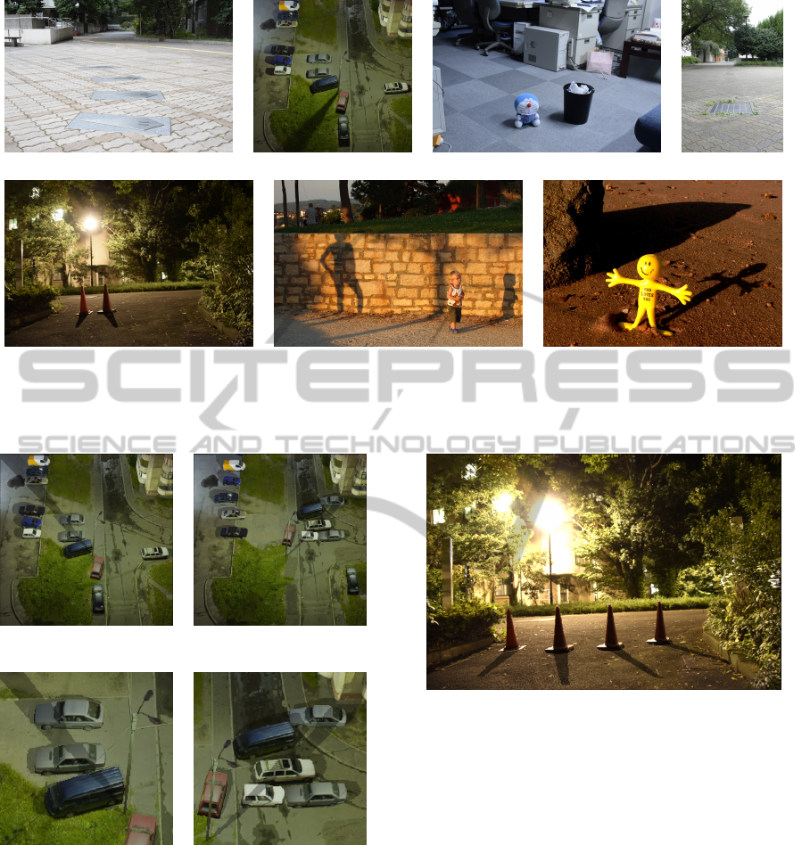
(a) (b) themactep (2005) (c) (d)
(e) (f) Sidorenko (2010) (g) Matthews (2010)
Figure 5: The images used in our experiments. (a), (c), (d), and (e) were taken by the authors. (b), (f) and (g) are from
Flickr and fall under the Attribution-NonCommercial-ShareAlike 2.0 Generic License released by Creative Commons (CC
BY-NC-SA 2.0).
(a) Relighting by moving the (b) Relighting by moving the
light. light and the cars.
(c) Zoom-in on the center (d) Zoom-in on the top-right
of (a). of (b).
Figure 6: The relighted results synthesized with 3D models
of cars and scene estimated from input image in Figure 5(b).
moving the light and cars. Obviously, the shadow of
the streetlamp in Figure 6 changes according to the
3D geometry.
Our system also allows the user to copy the es-
timated 3D models. Figure 7 shows the result af-
ter removing the traffic cone on the right in Figure
5(e), where the one on the left is duplicated multiple
Figure 7: Multiple traffic cones are synthesized at different
locations and cast shadows.
times and the duplicates are placed at different loca-
tions. We can see that the traffic cones cast visually
plausible shadows. In Figure 8, the multiple Dorae-
mon dolls from Figure 5(c) are put into the scene in
Figure 5(a), and each doll casts a shadow onto the
one on its right side. The 3D geometry of the dolls
can be perceived from the shadows on their feet and
faces. Figure 9 shows the result after moving the boy
from Figure 5(f) forward and inserting the Doraemon
doll from Figure 5(c) and the yellow doll from Fig-
ure 5(g) into the image. We can see that the boy casts
a shadow on the yellow doll and that the yellow doll
casts a shadow on the Doraemon doll. Note that the
shadow on the Doraemon doll’s face is cast by the
yellow doll’s hand.
Because it is extremely difficult to accurately es-
timate the back-face of an object, which is obviously
GRAPP2015-InternationalConferenceonComputerGraphicsTheoryandApplications
40
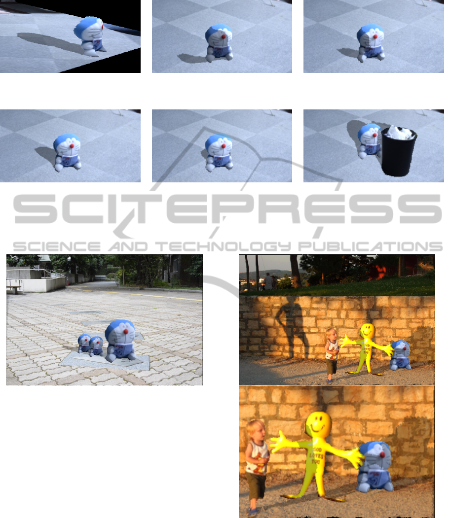
(a) Side-view of 3D model of Doraemon (b) Doraemon doll and its shadow cast by (c) The light in (b) is rotated clockwise.
doll estimated by our method. light coming from the right.
(d) The light in (c) is rotated clockwise (e) The light in (d) is rotated to the front of (f) The trash can casts a shadow on the doll,
again and the shadow seems more plausible. the doll and the shadow seems realistic. with which we can perceive the 3D
geometry of the doll.
Figure 10: The 3D model of the Doraemon doll recovered by our method (a) and the shadows cast by the light source placed
at different locations (b)-(e). The trash can casts realistic shadow on the doll in (f).
Figure 8: Inserting multiple Doraemon dolls from Figure
5(c) into Figure 5(a).
invisible in a single image, our method recovers only
the 3D geometry of the part of an object that is visi-
ble in the input image. Figure 10(a) shows the side-
view of the 3D model of the Doraemon doll estimated
by our method. Figure 10(b)-(e) shows its shadow
cast by light coming from different directions. Al-
though its cast-shadow seems incomplete when the
light comes from the side (Figure 10(b) and (c)), the
synthesized shadow is fine when the light comes from
the front of the doll (Figure 10(d) and (e)). Moreover,
in Figure 10(f), the shadow on the Doraemon doll cast
by the trash can also seems plausible. The results
of these experiments demonstrate that the 3D model
generated by our method produces realistic shadows
as long as the light is not coming from the side of the
objects.
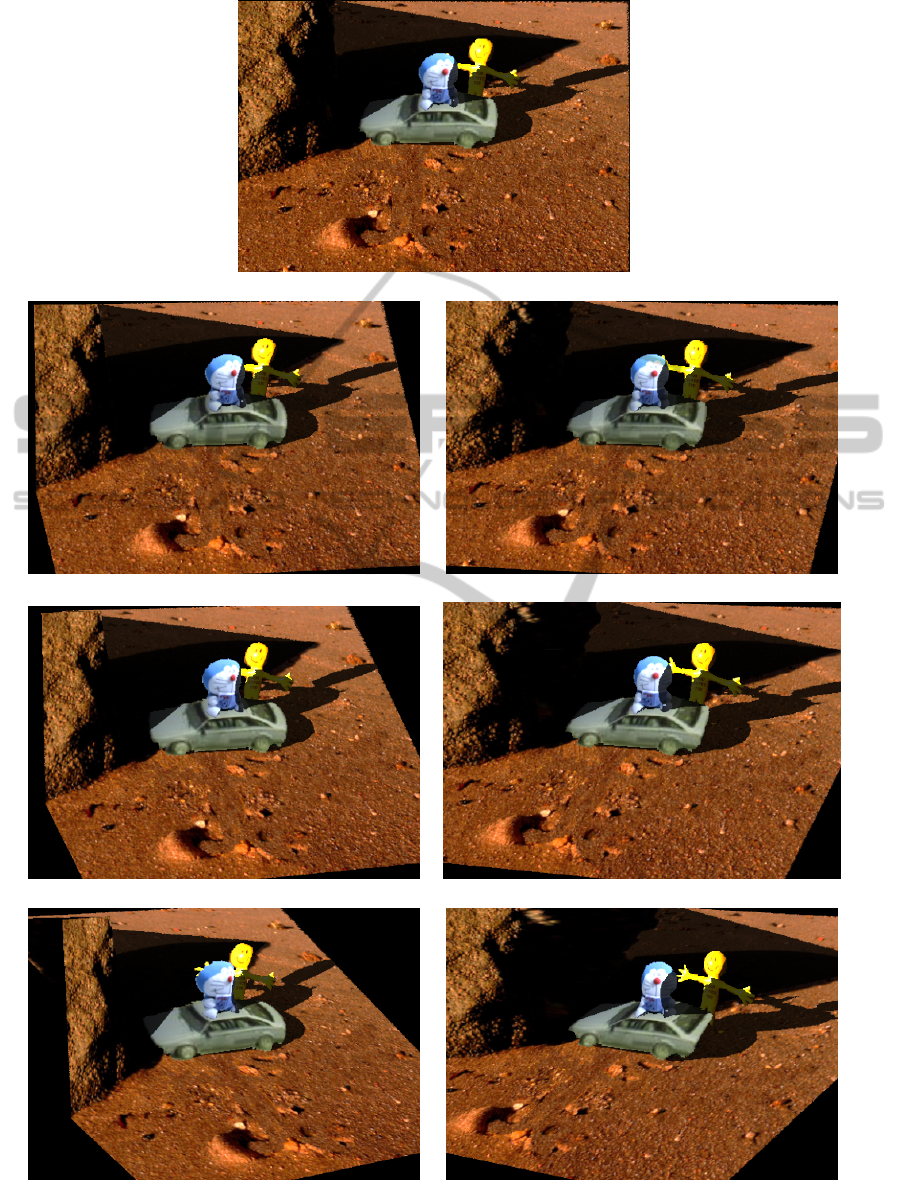
The 3D models generated by our method were
Figure 9: Top: Inserting doll from Figure 5(g) and Dorae-
mon doll from Figure 5(c) into Figure 5(f). Bottom: zoom-
in to see the shadows cast by the boy, and the dolls.
able to produce a visually plausible result even if
the viewing direction was slightly changed. Figure
11 shows the 3D models and scene estimated by our
method from different viewpoints, from which we can
see that the scene still seems plausible when the roll
SynthesizingRealisticShadowswithBumpySurfaceandObjectModelEstimatedbyShadowsinSingleImage
41
(a) Default viewpoint.
(b) Roll angle = -5
◦
. (c) Roll angle = 5
◦
.
(d) Roll angle = -10
◦
. (e) Roll angle = 10
◦
.
(f) Roll angle = -20
◦
. (g) Roll angle = 20
◦
.
Figure 11: Viewing the 3D models and scene estimated by our method from different viewpoints. The camera is aimed at the
center of the scene and roll rotation with different angles is then applied.
GRAPP2015-InternationalConferenceonComputerGraphicsTheoryandApplications
42
angle is about ten degrees (Figure 11(b)(c)). How-
ever, due to lack of back-face, when the roll angle
becomes twenty degrees, we clearly see that the trunk
of the car in Figure 11(g) does not exist.
(a) The shadow rendered on a (b) The shadow rendered on a
plane. bumpy surface.
(c) Zoom-in to see the shadow (d) Zoom-in to see the shadow
in (a). in (b).
Figure 12: The shadow rendered onto a plane (a)(c) and
onto a bumpy surface recovered by our method (b)(d).
Figure 13: The 3D geometry of a brick paver with metal
panel decoration retrieved by approach of Khan et al. (2006)
(left) and our method (right).
In addition to the 3D model of an object, we tested
our bumpy surface recovery method on surfaces made
of different materials. Figure 12 shows the shadow
rendered onto plain (a)(c) and bumpy surfaces recov-
ered by our method (b)(d). Obviously, the widths of
the shadows in Figure 12(c) are almost the same. In
contrast, the shadow in Figure 12(d) seems to be cast
on waves, and its width evidently changes accord-
ing to the concaves and convexes of the surface, from
which the 3D geometry is easily perceived.
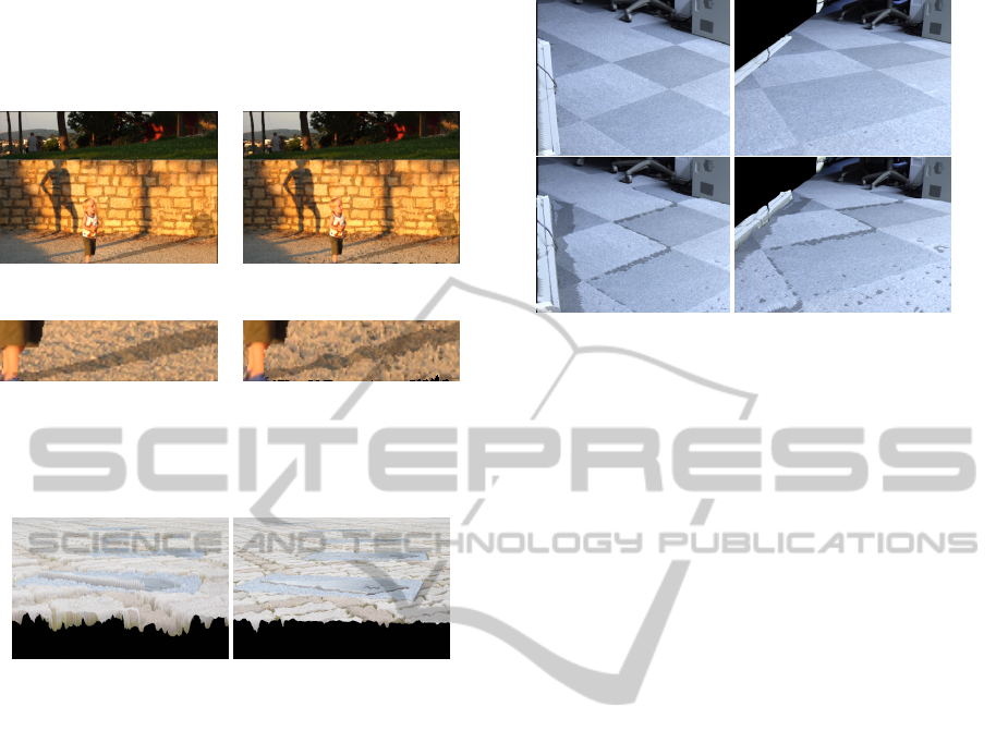
We compared our bumpy surface recovery method
with Khan et al. (2006), which uses the intensity of
pixel color as depth. As indicated in Figure 13, we
found that while both methods recover the gaps be-
tween bricks, their method tends to generate blocks
with different altitudes, e.g., the metal panel in Fig-
ure 13 seems to have sunk into the ground. Figure 14
shows this problem more clearly. The shadows in Fig-
ure 14(bottom), in which the scene is reconstructed
by Khan et al. (2006), imply that the carpet is sep-
arated into several blocks with different altitudes, so
that shadows appear at the boundary between blocks
of different colors. In contrast, our method recon-
structs the 3D geometry of the carpet as a plane, so
Figure 14: The 3D geometry of carpet retrieved by our
method (top row) and by the approach of Khan et al. (2006)
(bottom row). We show the scene viewed from a different
direction in the column on the right.
there is no shadow in Figure 14(top).
Our method generates a smooth surface even on
the edge between different colors by considering lo-
cal albedo. However, since local albedo is obtained by
superpixels, the size of the superpixels plays an im-
portant role in the computation of bump height. Fig-
ure 15 shows the 3D geometry of the scene in Fig-
ure 5(d) obtained with superpixels of different sizes.
If the size of the superpixels is too small, most of
the convexes and concaves are not generated (Figure
15(a)) because the superpixels are too small to gather
enough pixels and the correct albedo might not there-
fore be obtained. On the other hand, if the size of
the superpixels is too large, the superpixels can no
longer keep local information. Figure 15(c) and (d)
shows the results obtained with over-sized superpix-
els, where we can clearly see that the bars of the drain
ditch and the bricks protrude into the air. Figure 15(b)
shows the result obtained with superpixels of an ap-
propriate size, where the weeds cast self-shadows and
the bricks do not seem to be protruding. This indicates
that the size of the superpixels must be carefully cho-
sen to generate proper 3D geometry for bumpy sur-
faces.
5 CONCLUSION
We proposed a method to compute the bump heights
for a bumpy surface and a method to create 3D models
for the objects, ground, and walls that requires only
a single input image and a small amount of user an-
notation. The generated 3D models are sufficient for
rendering realistic shadows and the recovered bumpy
surface is useful to synthesize visually plausible im-
ages.
SynthesizingRealisticShadowswithBumpySurfaceandObjectModelEstimatedbyShadowsinSingleImage
43
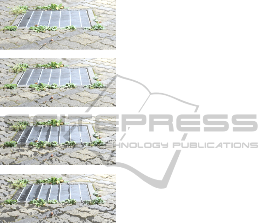
(a) 3 × 3 pixels.
(b) 40 × 40 pixels.
(c) 100 × 100 pixels.
(d) 160 × 160 pixels.
Figure 15: The 3D geometry of brick paver and drain ditch
cover recovered by our method with superpixels of different
sizes.
Experimental results show that our method can
recover 3D models for a variety of objects, includ-
ing dolls, humans, and cars, and that our bumpy sur-
face recovery method is more robust than the previous
work. Although our method only estimates the 3D ge-
ometry of the part of a scene that is visible in the input
image, a realistic synthetic image is still visible even
with a little bit of change in the viewing direction.
In future work, we wish to recover the hidden part
of an object by considering the symmetry of the ob-
ject or by different user annotations so that more op-
erations (e.g., object rotation) are allowed.
We also want to improve our current method to
the point where it is applicable to soft shadows. Un-
like hard shadows, a soft shadow does not specifically
indicate the shape of the 3D model that casts it. The
method proposed by Kee et al. (2013) may help solve
this problem.
REFERENCES
Abeles, P. (2013). Ejml: Efficient java matrix li-
brary. Retrieved July 2, 2013, from https://code.
google.com/p/efficient-java-matrix-library.
Barnes, C., Shechtman, E., Finkelstein, A., and Gold-
man, D. B. (2009). Patchmatch: a randomized cor-
respondence algorithm for structural image editing.
In ACM SIGGRAPH 2009 papers, SIGGRAPH ’09,
pages 24:1–24:11, New York, NY, USA. ACM.
Bousseau, A., Paris, S., and Durand, F. (2009). User-
assisted intrinsic images. ACM Trans. Graph.,
28(5):130:1–130:10.
Horry, Y., Anjyo, K.-I., and Arai, K. (1997). Tour into
the picture: Using a spidery mesh interface to make
animation from a single image. In Proceedings of
the 24th Annual Conference on Computer Graphics
and Interactive Techniques, SIGGRAPH ’97, pages
225–232, New York, NY, USA. ACM Press/Addison-
Wesley Publishing Co.
Iizuka, S., Kanamori, Y., Mitani, J., and Fukui, Y. (2011).
An efficient modeling system for 3d scenes from a
single image. IEEE Computer Graphics and Appli-
cations, 99.
Johnston, S. F. (2002). Lumo: Illumination for cel anima-
tion. In Proceedings of the 2Nd International Sympo-
sium on Non-photorealistic Animation and Rendering,
NPAR ’02, pages 45–ff, New York, NY, USA. ACM.
Karsch, K., Hedau, V., Forsyth, D., and Hoiem, D. (2011).
Rendering synthetic objects into legacy photographs.
In Proceedings of the 2011 SIGGRAPH Asia Confer-
ence, SA ’11, pages 157:1–157:12, New York, NY,
USA. ACM.
Kee, E., O’Brien, J. F., and Farid, H. (2013). Exposing
photo manipulation with inconsistent shadows. ACM
Trans. Graph., 32(3):28:1–28:12.
Khan, E. A., Reinhard, E., Fleming, R. W., and B
¨
ulthoff,
H. H. (2006). Image-based material editing. In ACM
SIGGRAPH 2006 Papers, SIGGRAPH ’06, pages
654–663, New York, NY, USA. ACM.
Kholgade, N., Simon, T., Efros, A., and Sheikh, Y. (2014).
3d object manipulation in a single photograph using
stock 3d models. ACM Trans. Graph., 33(4):127:1–
127:12.
Matthews, L. (2010). long shadows on 21 december 2010 -
day 355. From flickr https://www.flickr.com/photos/
mythoto/5279547375/. Attribution-NonCommercial-
ShareAlike 2.0 Generic license released by Creative
Commons (CC BY-NC-SA 2.0).
Savarese, S., Andreetto, M., Rushmeier, H. E., Bernardini,
F., and Perona, P. (2007). 3d reconstruction by shadow
carving: Theory and practical evaluation. Interna-
tional Journal of Computer Vision, 71(3):305–336.
Sidorenko, O. (2010). Luka, ira and their long shad-
ows. From flickr https://www.flickr.com/photos/
GRAPP2015-InternationalConferenceonComputerGraphicsTheoryandApplications
44

oksidor/5083256263/. Attribution 2.0 Generic license
released by Creative Commons (CC BY 2.0).
Sorkine, O. and Alexa, M. (2007). As-rigid-as-possible
surface modeling. In Proceedings of EUROGRAPH-
ICS/ACM SIGGRAPH Symposium on Geometry Pro-
cessing, pages 109–116.
themactep (2005). Kaliningrad night lights. From flickr
https://www.flickr.com/photos/themactep/42854712/.
Attribution-NonCommercial-ShareAlike 2.0 Generic
license released by Creative Commons (CC BY-NC-
SA 2.0).
Wang, J. and Wang, X. (2012). Vcells: Simple and efficient
superpixels using edge-weighted centroidal voronoi
tessellations. IEEE Trans. PAMI, 34(6): pp. 1241-
1247.
Williams, L. (1978). Casting curved shadows on curved sur-
faces. In Proceedings of the 5th Annual Conference on
Computer Graphics and Interactive Techniques, SIG-
GRAPH ’78, pages 270–274, New York, NY, USA.
ACM.
Wu, T.-P., Tang, C.-K., Brown, M. S., and Shum, H.-Y.
(2007). Natural shadow matting. ACM Trans. Graph.,
26(2).
Zheng, Y., Chen, X., Cheng, M.-M., Zhou, K., Hu, S.-M.,
and Mitra, N. J. (2012). Interactive images: cuboid
proxies for smart image manipulation. ACM Trans.
Graph., 31(4):99:1–99:11.
SynthesizingRealisticShadowswithBumpySurfaceandObjectModelEstimatedbyShadowsinSingleImage
45
