
In-plane Rotational Alignment of Faces by Eye and Eye-pair Detection
M. F. Karaaba, O. Surinta, L. R. B. Schomaker and M. A. Wiering
Institute of Artificial Intelligence and Cognitive Engineering (ALICE), University of Groningen,
Nijenborgh 9, Groningen 9747AG, The Netherlands
Keywords:
Eye-pair Detection, Eye Detection, Face Alignment, Face Recognition, Support Vector Machine.
Abstract:
In face recognition, face rotation alignment is an important part of the recognition process. In this paper, we
present a hierarchical detector system using eye and eye-pair detectors combined with a geometrical method
for calculating the in-plane angle of a face image. Two feature extraction methods, the restricted Boltzmann
machine and the histogram of oriented gradients, are compared to extract feature vectors from a sliding win-
dow. Then a support vector machine is used to accurately localize the eyes. After the eye coordinates are
obtained through our eye detector, the in-plane angle is estimated by calculating the arc-tangent of horizontal
and vertical parts of the distance between left and right eye center points. By using this calculated in-plane
angle, the face is subsequently rotationally aligned. We tested our approach on three different face datasets:
IMM, Labeled Faces in the Wild (LFW) and FERET. Moreover, to compare the effect of rotational aligning on
face recognition performance, we performed experiments using a face recognition method using rotationally
aligned and non-aligned face images from the IMM dataset. The results show that our method calculates the
in-plane rotation angle with high precision and this leads to a significant gain in face recognition performance.
1 INTRODUCTION
Alignment of a face after the detection from a still im-
age has crucial importance before the image is given
to any face recognition algorithm to obtain accurate
results. In particular, rotational alignment is neces-
sary after locating the face, since in unstructured en-
vironments the face can appear in any angle rather
than frontal. There are three types of rotation angle
parameters which determine the pose of a face: roll
(in-plane), yaw and pitch. Since the roll angle exists
in 2D (hence it is also called in-plane), aligning of it
is easier than the other angle parameters. Yaw and
pitch angles exist in 3D, and aligning faces which are
transformedby such rotations is much harder,because
the aligning method has to deal with invisible or de-
formed parts of the face. We here propose an in-plane
alignment of a face using eye coordinates that are au-
tomatically found in a face image. In this way we aim
to obtain in future work high recognition results with
a face recognition algorithm, without the need to use
full 3D modeling techniques.
Related Work. For aligning a face image, three gen-
eral methods have been used: statistical appearance
modeling methods, local features methods and geo-
metric calculation methods.
In the first approach, two related methods called
Active Shape Models (ASM) (Cootes et al., 1995)
and Active Appearance Models (AAM) (Cootes et al.,
1998) are popular where statistical information ob-
tained from sample training data is used. The sim-
plest of these methods is ASM. In the ASM method,
one manually labels a number of facial landmarks as
salient points on example faces used for training the
system. These landmark points are then used to model
the facial shape. Since positions of these points are
correlated, the PCA method is further applied to ob-
tain principal components describing the variances of
the point distributions and to make the further calcu-
lations computationally more efficient. Since shape
information is not sufficient for modeling some com-
plex face data, the AAM method, which is an exten-
sion of ASM, has been proposed. AAM combines the
shape model with texture information for improving
the face recognition system. With both approaches,
especially with the latter one, promising results have
been obtained. Nevertheless, an intensive labeling ef-
fort to obtain all salient points in the training images
is required to train these systems.
In the second approach, one uses local features by
implementing a local feature extractor without exam-
ining global information. An example method for this
392
Karaaba M., Surinta O., Schomaker L. and Wiering M..
In-plane Rotational Alignment of Faces by Eye and Eye-pair Detection.
DOI: 10.5220/0005308303920399
In Proceedings of the 10th International Conference on Computer Vision Theory and Applications (VISAPP-2015), pages 392-399
ISBN: 978-989-758-090-1
Copyright
c
2015 SCITEPRESS (Science and Technology Publications, Lda.)

approach, proposed recently in (Anvar et al., 2013),
utilizes the Scale Invariant Feature Transform (SIFT)
(Lowe, 2004) algorithm as a local feature detector.
Here, only one face is labeled with two reference
points (the mid-point between two eyes and the tip
of the nose) and using the reference information, the
rest of the training face images are described automat-
ically using SIFT features. Then a Bayesian classifier
is trained on the patches, which are composed of face
and non-face SIFT patches, to eliminate non-face fea-
tures. Since SIFT features include orientation infor-
mation for each facial feature found, this information
is used to estimate the rotation angle. However, high-
quality face images, which are not available for every
application field, are generally a prerequisite for the
SIFT algorithm to perform accurately.
In the third approach, some landmark points lo-
calized by detectors are used to determine the cor-
rect alignment position of a face. The points used to
align a face are usually central points of the eyes, and
sometimes the mouth and tip of the nose. After locat-
ing these points by a corresponding detector, the face
rotation angle can be estimated and the face can be
rotated geometrically. In this approach, because the
performance of the aligner will depend on the per-
formance of the detectors, detector design becomes
an important part of the method. There are two dif-
ferent approaches for detectors: the ones which are
implemented using mathematical operators describ-
ing object specific information and the others which
learn object specific information from sample images.
While the methods using the former approach are also
called shape-based models, the methods which are
based on the latter approach are called appearance-
based models. While the former one is faster, its per-
formance strictly depends on the specification of the
object to be found. The latter one is slower but more
robust to illumination and other noise sources that ex-
ist in real-world data (Hansen and Ji, 2010).
To localize an object, using two or more layered
systems has been shown to obtain a performance im-
provement. In (Li et al., 2010), such an approach
has been used to align faces. In that paper, a two-
layered eye localization method is adopted such that
in the first layer a mathematical operator named Fast
Radial Symmetry Transform is implemented to find
the points with high radial symmetry in a given im-
age. After locating eye candidate points by this opera-
tor, the eye classifier of Castrillon (Castrill´on-Santana
et al., 2008) is applied to eliminate false candidate
points and to finally locate the eyes in a face image.
After the localization, the in-plane rotation angle is
estimated by using the central points of the left and
right eye. In (Monzo et al., 2011), another hierarchi-
cal method is implemented. Here, in the first layer
the Adaboost classifier using Haar-like features sup-
plies many promising eye candidates to the second
layer. Then the second layer implementing the his-
togram of oriented gradients (Dalal and Triggs, 2005)
and a Support Vector Machine (SVM) is used to lo-
calize eyes.
Contributions. In this paper, we propose a simple
yet robust automatic face rotational alignment method
in which the in-plane rotation angle of a face is esti-
mated using the eye locations found by eye and eye-
pair detector systems. Eyes are localized by the eye
detector that searches for eyes in an eye-pair patch
obtained with our previously proposed eye-pair de-
tector (Karaaba et al., 2014). The eye detector is im-
plemented by using a feature extractor and a clas-
sifier. The method for each detector is based on a
sliding window approach. We make use of the re-
stricted Boltzmann machine (RBM) (Hinton, 2002)
and the histogram of oriented gradients (HOG) (Dalal
and Triggs, 2005) to extract features from the patches
belonging to the sliding window. Then the extracted
features and presented to a support vector machine
classifier (SVM) (Vapnik, 1998). The eye-pair detec-
tor is implemented by using an RBM and an SVM. In
this paper, we compare the effects of the HOG and the
RBM to study their utility for eye detection.
After locating the eyes in a face image, the in-
plane angle is calculated geometrically with the arc-
tangent formula using x and y distances between the
two detected eyes. Finally, the face is rotated by us-
ing that angle. We have tested our method on (subsets
of) three different face datasets, namely IMM (Nord-
strøm et al., 2004), FERET (Phillips et al., 1998) and
LFW (Huang et al., 2007). Our datasets contain 240,
230 and 450 face images, respectively. We have cho-
sen to use subsets in order to save time on prepara-
tion of the datasets and on testing of the methods. We
evaluate the performance of our method based on two
different evaluation criteria: eye localization error and
rotation error. The results show that the RBM feature
extraction method performs slightly better than the
HOG method on in-plane angle estimations. More-
over, we have also compared the use of rotationally
aligned faces to non-aligned faces using a simple but
robust face recognition system. The results of that ex-
periment prove that rotational alignment of a face has
a high impact on the recognition performance.
Paper Outline. The rest of the paper is organized
as follows: In Section 2, the feature extraction tech-
niques are described in detail. In Section 3, the eye-
pair and eye detectors are described together with the
method used for computing the rotation angle. In
Section 4, the experimental platform, the evaluation
In-planeRotationalAlignmentofFacesbyEyeandEye-pairDetection
393

methods, and the results of the experiments are pre-
sented. In Section 5, we conclude this paper.
2 FEATURE EXTRACTION
We will explain in this section the Restricted Boltz-
mann Machine (RBM) (Hinton, 2002) and the his-
togram of oriented gradients (HOG) (Dalal and
Triggs, 2005), which are used as feature extraction
methods.
2.1 Restricted Boltzmann Machines
An RBM is an energy-based neural network model
used for suppression of noise and reducing the dimen-
sionality of the input data. It is composed of two lay-
ers: an input layer and a hidden layer, which are con-
nected to each other through (symmetric) weighted
connections. There are many possible implementa-
tion methods of these layers depending on the struc-
ture of the data to be modeled. While the two layers
can be implemented with the same layer type, differ-
ent activation functions in different layers can also be
used. The binary stochastic layer is the most prevalent
implementation. We adopted in this paper, however, a
linear layer for the input units and a logistic layer for
the hidden units as this obtained the best performance
in our experiments. The mathematical description of
the RBM is briefly given below.
Let v
i
be the value of input unit i and h
j
be the ac-
tivity value of hidden unit j that models the input data
and ˆv
i
,
ˆ
h
j
are reconstructed input and hidden values.
h
j
is computed from the input vector by:
h
j
= f(b
j
+
∑
i
v
i
w
ij
) (1)
ˆv
i
and
ˆ
h
j
are computed as:
ˆv
j
= f(a
j
+
∑
i
h
i
w
ji
),
ˆ
h
j
= f(b
j
+
∑
i
ˆv
i
w
ij
) (2)
where f(·) is the activation function, a
j
is the bias for
input unit j, b
j
is the bias value for hidden unit j and
w
ij
’s are weights connecting input and hidden units.
For the linear function f(x) = x and for the logistic
function f(x) =
1
1+exp(−x)
.
To build a model using RBMs, the weight vector
w is to be optimized. The most often used method to
find the best weight vector, proposed by Hinton (Hin-
ton, 2002), is the contrastive divergence algorithm. In
this algorithm, the weight vector w is optimized ac-
cording to the following update rule:
∆w
ij
= η(hv
i
h
j
i − h ˆv
i
ˆ
h
j
i) (3)
where η is the learning rate, ˆv are reconstructed values
of the input data and
ˆ
h are reconstructed values of the
hidden units. The angle brackets denote the expected
value of any v
i
, h
j
pair, which are computed using a
batch of training examples. Biases are updated by:
∆a
i
= η(hv
i
i − h ˆv
i
i), ∆b
j
= η(hh
i
i − h
ˆ
h
i
i) (4)
After the optimization process, values of h
j
are
computed with the RBM given the input vector and
then given to a classifier as a feature vector.
2.2 Histograms of Oriented Gradients
The histogram of oriented gradients, proposed first by
(Dalal and Triggs, 2005) for pedestrian detection, is a
feature extraction technique which computes the ori-
ented gradients of an image using gradient detectors.
It has been applied since then in many other object de-
tection systems such as for faces (Zhu and Ramanan,
2012) and on-road vehicles (Arr´ospide et al., 2013),
as well as for object recognition like for recognizing
faces (D´eniz et al., 2011), emotions (Dahmane and
Meunier, 2011) and even actions (Wang et al., 2011).
The mathematical description of the HOG is
briefly presented below:
G
x
= I(x+ 1, y) − I(x− 1, y) (5)
G
y
= I(x, y + 1) − I(x, y− 1) (6)
where I(x, y) is the intensity of the pixel at position
(x, y), and G
x
and G
y
are the horizontal and vertical
components of the gradients, respectively.
M(x, y) =
q
G
2
x
+ G
2
y
(7)
θ
x,y
= tan
−1
G
y
G
x
(8)
While M(x, y) is the magnitude of gradients, θ
x,y
is
the angle of the gradient at the given location. There
are mainly two HOG descriptor calculation methods:
Circular HOG (C-HOG) and Rectangular HOG (R-
HOG). In this paper, we used the R-HOG method. In
the R-HOG method, the image to be processed is di-
vided into blocks which are composed of pixels. For
each block a separate histogram is constructed after
which all histograms are concatenated to form the fea-
ture vector.
As seen from the equations, angles and magni-
tudes are calculated from the gradients. In the HOG
descriptor angles are grouped using orientation bins.
The orientation bins are used to select angles for
which magnitudes of gradients are collected. The ap-
propriate bin b
θ
for some angle θ
x,y
is computed by:
b
θ
= ⌈
θ
x,y
B
2π
⌉, 0 ≤ θ ≤ 2π, 0 ≤ b
θ
≤ B (9)
VISAPP2015-InternationalConferenceonComputerVisionTheoryandApplications
394

where B is the bin size.
The calculated contributions of each pixel to the
appropriate bin are weighted using the magnitudes
and summed up in the final histogram.
3 EYE AND EYE-PAIR
DETECTION
Here, our novel hierarchical detector system based on
eye-pair and eye detectors is explained. In this sys-
tem, it is assumed that a face is detected in a picture
by a face detector, therefore we focus only on the eye-
pair and eye detection process before the alignment.
The system is comprised of two detection layers. In
the first layer, the eye-pair detector searches for an
eye-pair in an image containing a face. After the eye-
pair is found, the eye detector, which is in the second
layer, looks for the eyes in the eye-pair region. So,
the eye detector assumes its input image is an eye-pair
image rather than a face image. Decreasing the search
space hierarchically like described above has as ad-
vantage that false positives can be greatly reduced in
number. Both detectors use a sliding window method
to locate the object of their interest and use a detector
frame of fixed resolution. On the other hand, an input
image is rescaled in a predefined range of resolutions
preserving the aspect ratio of the detector frame.
3.1 Training Set Construction
To train the eye-pair and eye detector, we first created
a face image dataset manually by collecting images
containing human faces from the Internet. Although
the faces in the images we collected are in different
zoom levels, we kept the face-to-image zoom ratio al-
ways bigger than 0.5 during cropping. In addition,
the collected faces are in various positions and illu-
mination levels making them useful for eye-pair and
eye detection purposes in uncontrolled environments
(Karaaba et al., 2014). We will now present details
about the training dataset collection for the eye detec-
tor and additional dataset collection for the eye-pair
detector to make it more robust to rotated faces.
Eye Detector Dataset. To construct the eye dataset,
we first cropped eye regions of the faces which are
around 400 in number. We then added mirrored ver-
sions of them to the eye dataset. To obtain nega-
tives, we have used two different methods. The first
one is automatic non-eye image collection using ini-
tial eye ground truth information and the second one
is obtaining the negatives by testing the system with
our initially trained detector. We used approximately
two times more image patches (for both the positive
and negative set) than for the eye-pair dataset used in
(Karaaba et al., 2014).
Further Additions. To make the system more ro-
bust to rotated faces, we have rotated the face sam-
ples in the training sets using angles of ±5
◦
, ±10
◦
,
±15
◦
, ±20
◦
using the initial in-plane angle of the
faces computed from the manually selected eye co-
ordinates. After this automatically cropped eye-pair
and eye regions using the ground truth information of
original cropped patches are added to the training set.
After we aggregated around 1,200 new eye-pairs, we
tested the systems (eye and eye-pair detector) on the
training set of face images and collected more nega-
tives. The final amount of images in the eye-pair and
eye detector datasets increased to 7,000 and 13,500,
respectively.
Sample eye-pair pictures used to train the eye-pair
detector (in original resolution) are shown in Figure 1.
Sample eye and non-eye pictures (in original resolu-
tion) are shown in Figure 2.
To locate the eyes, the SVM is invoked on all win-
dows of the sliding window with the appropriate fea-
ture vector extracted from the window patch, and fi-
nally the highest outputs of the SVM are selected as
the locations of the eyes.
Figure 1: Sample eye-pair regions for training the eye-pair
detector.
(a) (b)
Figure 2: Sample eye (a) and non-eye (b) regions cropped
from eye-pair image patches. Note that the non-eye regions
may still contain eyes, but they are not very precisely lo-
cated in the center.
In-planeRotationalAlignmentofFacesbyEyeandEye-pairDetection
395
3.2 Calculating the Roll Angle
After locating the two eyes, the arctangent formula is
used for roll angle calculation:
angle = arctan(
y
x
) (10)
Where
y = eye(left)
y
− eye(right)
y
(11)
x = eye(left)
x
− eye(right)
x
(12)
Where eye(left) and eye(right) denote the central
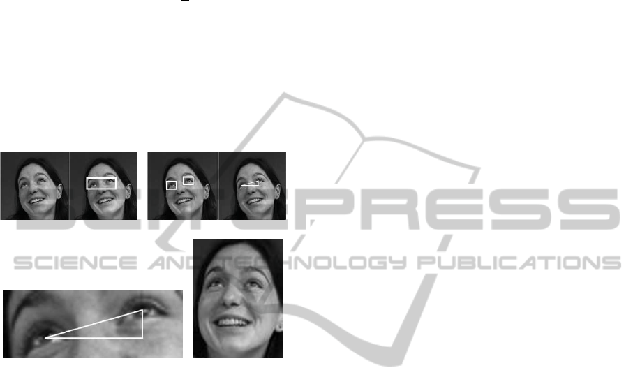
points of the two eyes. In Figure 3 a graphical rep-
resentation of the roll angle estimation and the face
alignment method can be seen.
(a) (b)
(c) (d)
Figure 3: Rotation angle estimation stages: (a) finding eye-
pair, (b) finding eyes from eye-pair, (c) computing the angle
from central coordinates of eyes (17.5
◦
in this example), (d)
rotationally aligned face.
4 EXPERIMENTAL SETUP AND
RESULTS
In this section general experimental parameters, the
face datasets which are used in the experiments, the
formulas used for evaluation, and finally the eye de-
tection and in-plane rotation angle estimation results
are given. In our experiments, an SVM classifier
(Vapnik, 1998) has been employed and the RBF ker-
nel is used as non-linear kernel due to its separability
power and suitability to the datasets we used.
4.1 Experimental Parameters
For the eye-pair detector we used the same aspect ra-
tio as in (Karaaba et al., 2014). For the eye detector
the ratio of a frame is selected as 1.38. The resolu-
tion used in the eye detector which uses the RBM as
the feature extractor is 18×13 and it is 36×27 for the
eye detector which uses HOG. We use 50 hidden units
for the RBM and around 100 epochs are employed to
train the model. We use a starting learning rate as
0.03 and normalized the input data between 0 to 1 be-
fore giving them to the RBM. As for HOG, we chose
4×3×6 (4×3 as block partitioning and 6 bins). Ac-
cording to our observations, while higher feature di-
mensions for HOG gaveslightly better accuracy at the
expense of increased computation time, lower feature
dimensions gave poorer performance in comparison
to the current HOG parameters.
4.2 Datasets
For the tests, the IMM (Nordstrøm et al., 2004), the
FERET (Phillips et al., 1998) and the Labeled Faces
in the Wild (LFW) (Huang et al., 2007) face datasets
are used. We note that the images in these datasets
were only used in the testing stage. The IMM face
dataset belongs to the Technical University of Den-
mark and is composed of 240 images with 40 individ-
uals. The FERET dataset was created by the Defense
Advanced Research Projects Agency (DARPA) and
the National Institute of Standards and Technology
(NIST) for the purpose of testing face recognition al-
gorithms. The full dataset is composed of 2,413 facial
images with 856 individuals. We use 230 facial sam-
ples of the full dataset selected from the first 100 indi-
vidual folders for our experiments. The LFW dataset
is known for containing face images collected in to-
tally unconstrained environments. It contains approx-
imately 13,000 images of around 6,000 people. We
selected alphabetically the first 450 images from this
dataset. For all the selected images, we determined
the rotation angles using the manually established eye
coordinates. For some sample face pictures of these
test datasets, see Figure 4.
Pose differences caused by yaw and roll angle
changes are more prevalent in the IMM than in the
FERET dataset. The LFW dataset, on the other hand,
includes high variability of illumination and pose dif-
ferences which makes it very challenging for com-
puter vision algorithms.
4.3 Evaluation Methods
We have used two evaluation methods for our face
alignment method. The first one is the eye localiza-
tion error which is calculated by dividing the pixel
localization error by the eye-pair distance. The eye-
pair distance is here the Euclidean distance between
the central points of the two eyes. The localization
VISAPP2015-InternationalConferenceonComputerVisionTheoryandApplications
396
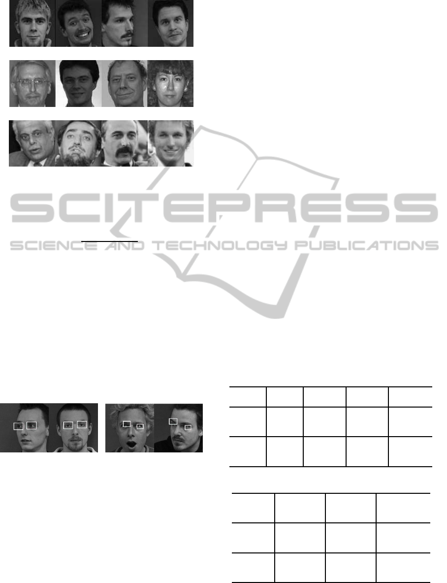
(a)
(b)
(c)
Figure 4: Sample face images of the test datasets (a) IMM,
(b) FERET and (c) LFW.
error is calculated as follows:
e =
d(d
eye
, m
eye
)
d(m
eye
l
, m
eye
r
)
(13)
where d(·, ·) in (13) denotes the Euclidean distance in
2D and in pixel units, d
eye
denotes the (center) coordi-
nates of the detected eye, m
eye
are the coordinates of
the manually cropped eye, m
eye
l
represents the coordi-
nates of the left eye, and m
eye
r
is the same for the right
eye. Some examples of face images where eyes are lo-
calized with an error lower or higher than a threshold
of 0.2 are depicted as rectangles in Figure 5.
The second evaluation method is the angle estima-
tion error which is calculated as the absolute value of
the difference between manually obtained and auto-
matically estimated angles (in degrees).
(a) (b)
Figure 5: Eyes localized with less (a) and more (b) than a
localization error of 0.2.
4.4 Results
In this section we will showthe results using the RBM
and HOG feature extraction methods with the SVM as
classifier.
We first show the eye localization errors in Table 1
and the rotation angle estimation errors in Table 2.
The average localization errors and rotation estima-
tion errors were computed on the natural data with-
out doing any additional artificial rotation. Instead
we computed the average errors from all the images
we selected for the datasets.
Table 1 shows the results for localizing the eyes.
The two feature extraction methods perform similarly.
The average localization errors are very small (much
smaller than the threshold of 0.2 shown in Figure 5).
This also makes the angle estimation errors in Table 2
very small, although the rotation errors are quite sen-
sitive to small errors in eye localization.
Table 1 also shows that, while we obtain the low-
est localization errors for the IMM dataset, the perfor-
mance of the method deteriorates when the method is
applied to the FERET and LFW datasets. Another
point is that error results on FERET are close to LFW
which is known as one of the hardest datasets due to
its realistic nature. The main reason for this is that al-
though LFW possesses complex backgroundsand rel-
atively low contrasted images, the images of FERET
vary much more in illumination than the images of the
other datasets (see Figure 4).
When we examine Table 2, the average rotation
errors are quite small. Meanwhile, although a corre-
lation can be seen between Table 1 and Table 2, lower
position errors do not directly imply lower rotation er-
rors. For instance, although average position error re-
sults of RBM are a bit higher than HOG results, aver-
age rotation estimation results look the opposite. This
observation suggests that calculation of rotation an-
gles are sensitive to stability of position information.
In this way, we can say that the RBM feature extrac-
tion method gives more stable position information
than the HOG method.
Table 1: Average Localization Error±Standard Error.
Method Dataset left eye right eye average
IMM .046±.002 .043±.002 .044±.002
RBM
LFW .071±.004 .069±.005 .070±.004
FERET .069±.009 .079±.011 .074±.01
IMM .044±.006 .041±.004 .042±.005
HOG
LFW .066±.003 .071±.005 .069±.004
FERET .064±.009 .071±.01 .067±.009
Table 2: Average Rotation Error ±Standard Error.
Method Dataset average er-
ror
successful
rotations
<2.5
◦
(%)
IMM 1.35±.066 90.0±1.9
RBM
LFW 2.30±.083 65.5±2.3
FERET 2.38±.118 80.9±2.6
IMM 1.47±.082 80.0±2.6
HOG
LFW 2.46±.096 63.4±2.3
FERET 2.64±.12 76.5±2.8
The results on the LFW dataset are quite promis-
ing when compared to previous results. We only
In-planeRotationalAlignmentofFacesbyEyeandEye-pairDetection
397
found one paper describing localization errors on
LFW, in (Hasan and Pal, 2011) average eye localiza-
tion errors on LFW are 0.081 for the left and 0.084
for the right eye. In this study, we obtained lower er-
ror rates as can be seen in Table 1.
As for a general comparison with other works, the
survey paper (Song et al., 2013) presents a lot of eye
detection results obtained with many other possible
methods. Our methods (using HOG and RBM fea-
ture extraction methods) outperform some of these
methods, although the results of the best methods pre-
sented in (Song et al., 2013) are better than the results
obtained with our method. To compare to those re-
sults, we want to mention that our best method ob-
tained 95% (96.9%) correctly detected eyes on Feret
with a eye localization threshold of 0.1 (0.25), and
85.4% (99%) on LFW with a threshold of 0.1 (0.25).
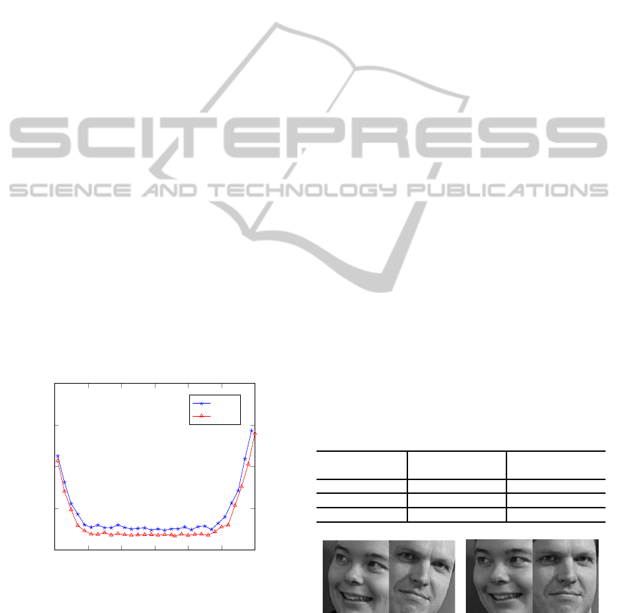
We also show the plot of the average angle esti-
mation errors in Figure 6. To construct the plot in
Figure 6, we first rotated every single face image in
one of the experimental datasets (IMM) to 0
◦
degrees
using the manually annotated coordinates of the eye
centers. Then, we rotated every image from -30
◦
to
30
◦
in steps of 2
◦
and for each angle we computed
the average rotation estimation error.
The error rates of the method are lowest between -
20
◦
and 20
◦
which corresponds to the range of angles
encountered in the training set for the eye detector.
Besides, a similar observation already seen in Table 1
and Table 2 about the performance of the two feature
extraction methods can also be noticed here. To con-
clude from all of these observations, the RBM seems
to better handle angle estimations than HOG.
−30 −20 −10 0 10 20 30
0
5
10
15
20
In-Plane Angles (Degree)
Error Between Actual and Estimated Angle
HOG
RBM
Figure 6: Angle estimation errors on the artificially rotated
IMM dataset, as a function of artificial face rotation angles
from -30
◦
to 30
◦
in steps of 2
◦
.
Face Recognition. We also show the effect of rota-
tional alignment on the performance of a face recog-
nition system. To make this comparison, we cropped
all face images in the IMM dataset according to the
eye coordinates. First, we created the Non-Rotated
dataset, see Figure 7(a), by cropping using detected
eye positions, without using angle information from
eye positions to rotationally align the faces. In this
way, the eye detection systems using HOG or RBM
still operate in a slightly different way.
Second, we made an Automatically Rotated
dataset, see Figure 7(b), by cropping after rotating by
using the angle information using the found eye posi-
tions.
Then, we used HOG with 3×3×9 parameter set-
tings (3× 3 as block resolution and 9 bins) and 60x66
pixels resolution as the input dimension to train the
face recognition system. As the IMM dataset con-
tains 6 images per person (6×40 = 240), we selected
4 images for each class as training data and 2 for
testing. Then we have in total 160 images for train-
ing and 80 images for testing. We subsequently gave
the computed HOG features to an SVM 1-to-All ap-
proach and used grid search to find the best meta-
parameters to train the model. We selected HOG
for this face recognition experiment particularly due
to its easy training properties and its relative robust-
ness to illumination variations. These results, how-
ever, should not be interpreted as results of an opti-
mally working face recognition system. With this ex-
periment, we aim to show the influence of rotational
alignment. Additionally, we examine the individual
effect of each feature extraction technique used in eye
detection. Table 3 shows that using automatically ro-
tated faces gives around 6 to 8 percent improvement
in recognition performance. If rotated faces are com-
pared by eye detection technique, the use of RBM in
the eye detection system gives a slightly better perfor-
mance than HOG and also gives the highest overall
performance.
Table 3: Face Recognition Results on IMM Dataset.
detected by detected by
RBM+SVM (%) HOG+SVM (%)
Non-Rotated 74.50 75.50
Auto. Rotated 82.75 81.75
Improvement 8.25 6.25
(a) (b)
Figure 7: (a) faces in original angle and (b) faces rotated
using the eye coordinates found by our best performing
method.
VISAPP2015-InternationalConferenceonComputerVisionTheoryandApplications
398

5 CONCLUSION
Face alignment is an important step to obtain good re-
sults with a face recognition system. In this paper, we
have presented a novel face alignment method based
on two detectors that operate hierarchically. In this
method, first the eye-pair location is found in the face
image by the eye-pair detector. Then an eye detector
uses the search region, which the eye-pair detector re-
turned, to find the locations of the eyes. This location
information is subsequently used to align faces by us-
ing a simple geometrical formula. For the eye detec-
tor, we also compared results of two feature extraction
techniques in eye localization and rotation angle esti-
mation. The results on three different datasets show
that the RBM feature extraction technique is better at
handling rotation angle estimation than HOG. This is
also supported by the angle estimation error plot cre-
ated by using artificially created angles. We finally
examined the effect of rotational alignment in a face
recognition experiment in which we compare the use
of rotationally aligned and non-aligned faces in a sim-
ple face recognition system. The results show that the
RBM feature extraction method gives the best angle
estimation performance and this in-turn results in bet-
ter performance in a face recognition system. In fu-
ture work we will primarily focus on optimizing the
face recognition algorithm, which will make use of
the rotation alignment method presented in this paper.
REFERENCES
Anvar, S., Yau, W.-Y., Nandakumar, K., and Teoh, E. K.
(2013). Estimating In-Plane Rotation Angle for
Face Images from Multi-Poses. In Computational
Intelligence in Biometrics and Identity Management
(CIBIM), 2013 IEEE Workshop on, pages 52–57.
Arr´ospide, J., Salgado, L., and Camplani, M. (2013).
Image-based on-road vehicle detection using cost-
effective histograms of oriented gradients. Journal
of Visual Communication and Image Representation,
24(7):1182–1190.
Castrill´on-Santana, M., D´eniz-Su´arez, O., Ant´on-Canal´ıs,
L., and Lorenzo-Navarro, J. (2008). Face and Facial
Feature Detection Evaluation. In Third International
Conference on Computer Vision Theory and Applica-
tions, VISAPP08, pages 167–172.
Cootes, T. F., Edwards, G. J., and Taylor, C. J. (1998).
Active Appearance Models. In IEEE Transactions
on Pattern Analysis and Machine Intelligence, pages
484–498. Springer.
Cootes, T. F., Taylor, C. J., Cooper, D. H., and Graham, J.
(1995). Active Shape Models - Their Training and Ap-
plication. Computer Vision and Image Understanding,
61(1):38–59.
Dahmane, M. and Meunier, J. (2011). Emotion recognition
using dynamic grid-based HoG features. In Automatic
Face Gesture Recognition and Workshops (FG 2011),
2011 IEEE International Conference on, pages 884–
888.
Dalal, N. and Triggs, B. (2005). Histograms of oriented gra-
dients for human detection. In Computer Vision and
Pattern Recognition, 2005. CVPR 2005. IEEE Com-
puter Society Conference on, volume 1, pages 886–
893.
D´eniz, O., Bueno, G., Salido, J., and la Torre, F. D. (2011).
Face recognition using histograms of oriented gradi-
ents. Pattern Recognition Letters, 32(12):1598–1603.
Hansen, D. W. and Ji, Q. (2010). In the Eye of the Beholder:
A Survey of Models for Eyes and Gaze. IEEE Trans-
actions on Pattern Analysis & Machine Intelligence,
32(3):478–500.
Hasan, M. K. and Pal, C. J. (2011). Improving Alignment
of Faces for Recognition. In Robotic and Sensors En-
vironments, pages 249–254. IEEE.
Hinton, G. E. (2002). Training Products of Experts by Mini-
mizing Contrastive Divergence. Neural Computation,
14(8):1771–1800.
Huang, G. B., Ramesh, M., Berg, T., and Learned-Miller,
E. (2007). Labeled faces in the wild: A database for
studying face recognition in unconstrained environ-
ments. Technical Report 07-49, University of Mas-
sachusetts, Amherst.
Karaaba, M. F., Wiering, M. A., and Schomaker, L. (2014).
Machine Learning for Multi-View Eye-Pair Detec-
tion. Engineering Applications of Artificial Intelli-
gence, 33(0):69 – 79.
Li, H., Wang, P., and Shen, C. (2010). Robust face recogni-
tion via accurate face alignment and sparse represen-
tation. In Digital Image Computing: Techniques and
Applications (DICTA), 2010 International Conference
on, pages 262–269.
Lowe, D. G. (2004). Distinctive Image Features from Scale-
Invariant Keypoints. International Journal of Com-
puter Vision, 60:91–110.
Monzo, D., Albiol, A., Sastre, J., and Albiol, A. (2011).
Precise eye localization using HOG descriptors. Ma-
chine Vision and Applications, 22(3):471–480.
Nordstrøm, M. M., Larsen, M., Sierakowski, J., and
Stegmann, M. B. (2004). The IMM face database - an
annotated dataset of 240 face images. Technical re-
port, Informatics and Mathematical Modelling, Tech-
nical University of Denmark, DTU.
Phillips, P. J., Wechsler, H., Huang, J., and Rauss, P. (1998).
The FERET database and evaluation procedure for
face recognition algorithms. Image and Vision Com-
puting, 16(5):295–306.
Song, F., Tan, X., Chen, S., and Zhou, Z.-H. (2013). A liter-
ature survey on robust and efficient eye localization in
real-life scenarios. Pattern Recognition, 46(12):3157
– 3173.
Vapnik, V. (1998). Statistical Learning Theory. Wiley.
Wang, H., Klaser, A., Schmid, C., and Liu, C.-L. (2011).
Action recognition by dense trajectories. In Computer
Vision and Pattern Recognition (CVPR), 2011 IEEE
Conference on, pages 3169–3176.
Zhu, X. and Ramanan, D. (2012). Face detection, pose es-
timation, and landmark localization in the wild. In
Computer Vision and Pattern Recognition (CVPR),
2012 IEEE Conference on, pages 2879–2886.
In-planeRotationalAlignmentofFacesbyEyeandEye-pairDetection
399
