
Real-time Human Pose Estimation from Body-scanned Point Clouds
Jilliam Mar
´
ıa D
´
ıaz Barros
1,2
, Frederic Garcia
2
and D
´
esir
´
e Sidib
´
e
1
1
Le2i - UMR CNRS 6306, Universit
´
e de Bourgogne, 12 rue de la Fonderie, Le Creusot, France
2
SnT, University of Luxembourg, 4 rue Alphonse Weicker, Luxembourg, Luxembourg
Keywords:
Human Pose Estimation, Point Cloud, Skeleton Model.
Abstract:
This paper presents a novel approach to estimate the human pose from a body-scanned point cloud. To do
so, a predefined skeleton model is first initialized according to both the skeleton base point and its torso
limb obtained by Principal Component Analysis (PCA). Then, the body parts are iteratively clustered and the
skeleton limb fitting is performed, based on Expectation Maximization (EM). The human pose is given by the
location of each skeletal node in the fitted skeleton model. Experimental results show the ability of the method
to estimate the human pose from multiple point cloud video sequences representing the external surface of
a scanned human body; being robust, precise and handling large portions of missing data due to occlusions,
acquisition hindrances or registration inaccuracies.
1 INTRODUCTION
Human pose estimation is indispensable in very active
research areas such as scene understanding, human-
computer interaction and action or gesture recogni-
tion. Among the vast literature on this fundamental
research topic, many authors have considered prede-
fined human models to simplify the pose estimation
task when using conventional 2-D cameras. For in-
stance, Ke et al. in (Ke et al., 2011) retrieve the human
pose from a monocular camera, using downhill sim-
plex algorithm to match 2-D feature points to a pre-
defined 3-D human model. Other approaches specif-
ically parameterize the pose in a lower dimensional
space, using skeleton models. An example is the work
of Li et al. in (Li et al., 2009), where the authors esti-
mate the 2-D human pose in a video sequence using a
predefined human skeleton model to fit the silhouette
of a body shape. Distance Transform (DT) and Prin-
cipal Component Analysis (PCA) are used to identify
the skeleton base point and to initialize the skeleton.
Then, they perform an iterative process to cluster the
body parts to which they fit the predefined skeleton
model. However, a renewed interest has arisen as a
side-effect of the recent advances in 3-D sensing tech-
nologies. Indeed, recent consumer-accessible depth
cameras such as the Kinect or the Xtion Pro Live pro-
vide remarkable advantages, such as easily overcom-
ing the background matting problem, i.e., segment-
ing foreground objects from the scene background.
Although recent approaches based on depth cameras
provide very promising human pose estimates, most
of them are intended for mono-view systems and thus
limited to applications in which the user is facing to
the camera. Approaches intended for multi-view sys-
tems and thus to estimate the human pose from a full
body scan, usually extract a curve-skeleton represen-
tation of the shape to which the skeleton model can
be fitted and hence, estimate the pose. However, these
approaches are impractical for applications in which
the human pose must be estimated in real-time.
In this paper, the problem of human pose estima-
tion is addressed in the context of 3-D scenes scanned
by multi-view systems composed of multiple depth
cameras. To enable for real-time applications, prior
knowledge such as a predefined human body skele-
ton model is also incorporated, from which its skele-
tal joints will define the configuration and thus the
pose of the scanned body. The remainder of this pa-
per is organized as follows: Section 2 presents a re-
view of human pose estimation based on depth sens-
ing. In Section 3 a detailed description of the current
approach is presented. Section 4 evaluates the pro-
posed approach on both synthetic and real data. Fi-
nally, concluding remarks are given in Section 5.
2 RELATED WORK
Related to single-depth-image pose estimation, Ye et
553
Díaz Barros J., Garcia F. and Sidibé D..
Real-time Human Pose Estimation from Body-scanned Point Clouds.
DOI: 10.5220/0005309005530560
In Proceedings of the 10th International Conference on Computer Vision Theory and Applications (VISAPP-2015), pages 553-560
ISBN: 978-989-758-089-5
Copyright
c
2015 SCITEPRESS (Science and Technology Publications, Lda.)

al. (Ye et al., 2011) proposed a pipeline to com-
bine pose detection with pose refinement. To do so,
the depth map is used to find a similar pose within
a database of prior full-body surface mesh models.
Lehment et al. (Lehment et al., 2010) considered 3-D
point clouds extracted from depth maps to fit a mesh
of a cylinder-based stickman model using Annealing
Particle Filters (APF). However, the aforementioned
methods require a GPU-based implementation. Shot-
ton et al. (Shotton et al., 2013) introduced two super-
real-time approaches to predict the positions of body
joints using a large and varied synthetic set of training
images. Decision forests and simple depth-invariant
image features are implemented. In (Zhang et al.,
2012), Zhang et al. considered a multi-view setup
with depth cameras to perform human pose estima-
tion and tracking. The method employs APF and par-
tition sampling in point cloud models, handles occlu-
sions and reduces ambiguities. The initial pose is esti-
mated using a coarse-to-fine search paradigm. To the
best of our knowledge, this is the only method using a
multiple-depth-camera setup for human pose estima-
tion. Curve-skeleton-extraction approaches have been
successfully used for different kind of shapes besides
human models. Since they preserve the geometry and
topological information of the object, they can be im-
plemented in human pose estimation by approximat-
ing the underlying skeletal structure (Garcia and Ot-
tersten, 2014b). Au et al. at (Au et al., 2008) proposed
a Laplacian-based contraction method intended only
for watertight mesh surfaces. An extension of this
work was proposed by Cao et al. (Cao et al., 2010)
to handle surfaces with boundaries, polygon soups
and point clouds. Although both methods are robust
against noise and moderate miss of data, they are not
optimized for real-time applications. Tagliasacchi et
al. presented in (Tagliasacchi et al., 2009) a method
to extract curve skeletons based on a generalized ro-
tational symmetry axis (ROSA) of an oriented point
cloud. A similar approach was proposed by Sam et al.
(Sam et al., 2012) using the antipodes as a reference.
Both methods can handle significant missing data, but
require parameter tuning. A real-time curve-skeleton
extraction method was proposed by Garcia and Otter-
sten (Garcia and Ottersten, 2014b) in which, inspired
from (Sam et al., 2012), the skeletal candidates are
extracted in the 2-D space and then back-projected to
the 3-D space. The algorithm is robust against signif-
icant portions of missing data. Limitations are related
to occluded body parts and limbs located very close
to each other.
(a) (b)
Figure 1: Predefined human skeleton model. (a) Skeleton
limbs and nodes. (b) Human body proportions, with hu the
height of the head (head units).
3 PROPOSED APPROACH
A novel approach to estimate the human pose from a
body-scanned point cloud P describing a set of 3-D
points p
i
= (p
x
, p
y
, p
z
) representing the underlying
external surface of a human body is outlined below.
Similarly to (Li et al., 2009), the current approach
has considered an articulated human skeleton model
composed of 15 nodes and 14 edges, presented in
Fig. 1 (a). By doing so, the complexity and flexibil-
ity of the human body as well as the high dimension-
ality of the pose space are reduced. The predefined
skeleton model represents a simplified version of the
geometry and topology of the human skeleton. Al-
though there are subtle differences between people,
human body proportions fit within a fairly standard
range and thus, prior knowledge can be considered.
Indeed, an average person uses to measure 7.5 times
the height of his head (including the head). This in
turn allowed to initialize the length of each skeleton
limb as shown in Fig. 1 (b) (Hum, 2014).
In this work, P describes any possible body con-
figuration of an upright person. Hence, the height of
a person (7.5 ×hu) is given by the difference between
the maximum and minimum z coordinates within P .
That is, hu = (p
z
max
− p
z
min
)/7.5, being the head the
highest body part.
The human pose estimation results from the con-
figuration of the skeletal joints after approximating
the aforementioned skeleton model. This is achieved
with a four-steps framework. First, both the base
point of the skeleton model and the torso orientation
are extracted. These two parameters allow the initial-
ization of the torso whereas the remaining skeleton
limbs are initialized by an iterative process in which
the best initial skeleton limb configuration is selected.
Next step concerns the clustering of the body parts,
VISAPP2015-InternationalConferenceonComputerVisionTheoryandApplications
554

to which finally, their respective skeleton limbs are
progressively approximated. The clustering and fit-
ting are performed under a framework based on the
theory of Expectation Maximization. Note that the
3-D point clustering to find the torso orientation (Sec-
tion 3.1) and the initialization of the skeleton model
using a predefined set of limb configurations (Sec-
tion 3.2) are solely performed for the first frame. In-
deed, the resulting fitted skeleton corresponds to the
initial skeleton for the consecutive frame. By doing
so, the time consumed during both stages is reduced,
ensuring a better initial skeleton estimate for the fol-
lowing frames.
3.1 Torso and Base Point Extraction
The node A = (A
x
,A
y
,A
z
) in Fig. 1 (a) corresponds
to the base point of the skeleton model whereas the
segment between nodes A and B, skeleton limb l
1
=
B − A, to the torso. The direction of the torso re-
sults from the Principal Component Analysis (PCA)
on P . Indeed, the direction of the principal compo-
nent v = (v
x
,v
y
,v
z
) coincides with the direction of the
torso, assuming that P describes an upright person.
The equation of the 3-D line in which the base point
A lies is thus defined from the centroid of P , i.e.,
¯
p =
1
k
·
∑
k
i=1
p
i
, ∀p
i
∈ P and the normalized vector v.
The third coordinate of A, i.e., A
z
, is retrieved from
the human body proportions denoted in Fig. 1 (b),
whereas the two missing coordinates result from:
A
x
= v
x
·t + ¯p
x
,
A
y
= v
y
·t + ¯p
y
,
(1)
with t = (A
z
− ¯p
z
)/(v
z
− ¯p
z
). Note that the initializa-
tion of the skeleton model and hence, the body clus-
tering, are strongly dependent on these two parame-
ters. Indeed, a wrong direction of the torso entails to
a wrong initialization of the model and thus to an erro-
neous pose in space. To increase the accuracy and ro-
bustness of the torso direction, only those 3-D points
that belong to the torso are considered. To do so, the
torso 3-D points are classified by fitting a cylinder,
a simplified geometric model that can be quickly fit-
ted to the dataset using Random Sample Consensus
(RANSAC) (Fischler and Bolles, 1981). Alternative
fitting algorithms with embedded heuristic hypothe-
ses generators can be also considered.
3.2 Initialization of the Skeleton Model
The initial skeleton model results from the skeleton
limb’s configuration that minimizes the distances be-
tween the 3-D points and the set of skeleton limbs,
(a) (b) (c) (d)
(e) (f) (g)
Figure 2: Considered skeleton limb and node configurations
to initialize the skeleton model (only right body side config-
urations are shown).
i.e., the best matching between the predefined skele-
ton model configuration and the given point cloud P .
However, in contrast to alternative approaches to es-
timate the human pose from 2-D images (Li et al.,
2009), this task is far from trivial when considering
the additional degree of freedom in a 3-D space. First,
the skeleton model is aligned to the estimated base
point and torso directions. Then, the locations of the
remaining skeleton nodes are progressively computed
from the set of skeleton limb configurations, pre-
sented in Fig. 2, and using incorporated prior knowl-
edge such as the radii of the skeleton limbs and the
initial angles of the skeleton joints. Fig. 2 only shows
the selected configurations to initialize the right body
side. Nevertheless, as can be inferred, the mirrored
versions correspond to the configurations of the left
body side. Given a skeleton limb l
i
with radius r
i
,
azimuthal angle θ
i
, and polar angle φ
i
, the 3-D coor-
dinates of the end node w = (w
x
,w
y
,w
z
) result from:
w
x
= u
x
+ r
i
· cos θ
i
· cos φ
i
,
w
y
= u
y
+ r
i
· sin θ
i
· cos φ
i
,
w
z
= u
z
+ r
i
· sin φ
i
,
(2)
with u = (u
x
,u
y
,u
z
) the 3-D coordinates of the initial
node. The spherical coordinate system and the right-
hand rule are used to define the initial angles that gen-
erate the coordinates of each skeleton node. The an-
gles θ and φ are fixed within the range of [0,π] and
[0,2π), respectively. First, the location of the skele-
ton nodes that are directly connected to the base point
A are computed, i.e., B, C, D and E. From them, the
location of F, G, H and I, followed by J, K, L and M
are computed. Finally, nodes N and O are computed.
When considering 3-D models that are differently
oriented with respect to the z-axis, the 2
nd
principal
component is used to rotate the initialized skeleton
Real-timeHumanPoseEstimationfromBody-scannedPointClouds
555
model. In the current system configuration, the eigen-
vector of the 1
st
component corresponds to the z-axis
whereas the eigenvector of the 2
nd
one corresponds to
the x-axis. Thereby, a 3 × 3 rotation matrix R is com-
puted by rearranging the eigenvectors obtained from
PCA. The new location of the skeleton nodes is given
by w = R · u.
3.3 Body Parts Clustering
After initializing the skeleton model, the cluster-
ing of the body parts to which each skeleton limb
will be further approximated is performed. To do
so, each 3-D point p
i
is assigned to the skeleton
limb l
k
to which the distance is minimum, i.e., l
k
=
argmin
k∈[1,14]
(d(p
i
,l
k
)) ∀p
i
∈ P .
Nevertheless, close distances between a 3-D point
and two or more skeleton limbs may induce to ambi-
guity in the clustering. Hence, these 3-D points are
not considered within the clustering process.
3.4 Skeleton Limb Fitting
Next step concerns the medial axis estimation of each
clustered body part, to which their corresponding
skeleton limb will be fitted. It is important to recall
that the nodes of the torso, A and B, are fixed in this
step, and the remaining nodes to be computed are only
connected to two limbs. From each cluster, the mean
point and the three principal components are extracted
using PCA. Note that the length of each skeleton limb
is known from Fig. 1 (b). To decide which of the three
eigenvectors corresponds to the medial axis, they are
stretched from both sides starting from the mean point
of the cluster and by half of their known length. As
a result, three potential medial axes that are not con-
nected to each other, but oriented towards the direc-
tions of the principal components, are obtained. The
connectivity between the skeleton limbs is ensured by
selecting the medial axis candidates of adjacent clus-
ters with the shortest distances between the end node
of the previously fitted limb and the initial node of
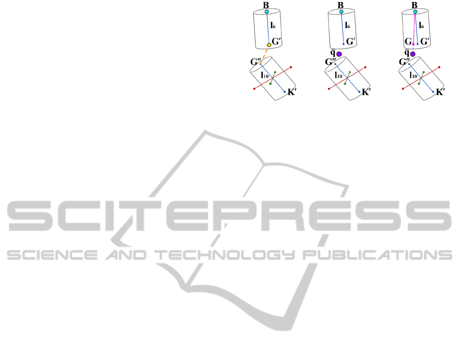
the limb to be fitted. Fig. 3 details the fitting pro-
cess between the left hip and left thigh skeleton limbs.
Red, blue and green segments are the candidate me-
dial axes of each cluster, depicted as cylinders. The
three candidates of each cluster have exactly the same
length, which corresponds to the length of their re-
spective skeleton limb. The yellow point in Fig. 3 (a)
denotes the end node of the hip limb G
0
, whereas
the orange dashed line is the shortest distance to the
skeletal node candidates of the adjacent cluster, i.e.,
G
00
. Next, the centroid
¯
q between G
0
and G
00
is cal-
culated, shown in purple color in Fig. 3 (b), and the
(a) (b) (c)
Figure 3: Fitting process of the hip limb. The medial axis
candidates corresponding to the first, second and third prin-
cipal components (in blue, red and green colors, respec-
tively).
fitting of l
6
is refined by reorienting it towards
¯
q, as
shown in Fig. 3 (c). The new 3-D coordinates of G
result from:
G = B + λ, (3)
with λ = d(B, G)·(
¯
q−B)/||
¯
q−B||. Note that node G
corresponds to the initial node of the adjacent skele-
ton limb, i.e., the thigh. Therefore, the skeleton limb
l
10
is translated to its respective location, which gives
an initial location for the node K, to be refined when
fitting its adjacent skeleton limb, i.e., l
14
.
3.5 Skeleton Refinement
Similarly to (Li et al., 2009), the fitting of the skeleton
model is performed through an iterative process based
on Expectation Maximization (EM). The Expectation
(E) step comprises Section 3.3 and the first part of
Section 3.4, where the expected human skeleton is
calculated for the current pose. The Maximization
(M) step corresponds to the last part of Section 3.3,
where the parameters that maximize the expectation
of the skeleton model during the fitting process are
computed. From the experiments, the fitting process
converges to a good pose estimation in only one or
two iterations.
4 EXPERIMENTAL RESULTS
The proposed human pose estimation approach is
evaluated on both real and synthetic data. All re-
ported results have been obtained using a Mobile
Intel
R
QM67 Express Chipset with an integrated
graphic card Intel
R
HD Graphics 3000. The pro-
posed approach has been implemented in C++ lan-
guage using the OpenCV (Bradski and Kaehler, 2008)
and PCL (PCL, 2014) libraries. Real data has been
VISAPP2015-InternationalConferenceonComputerVisionTheoryandApplications
556
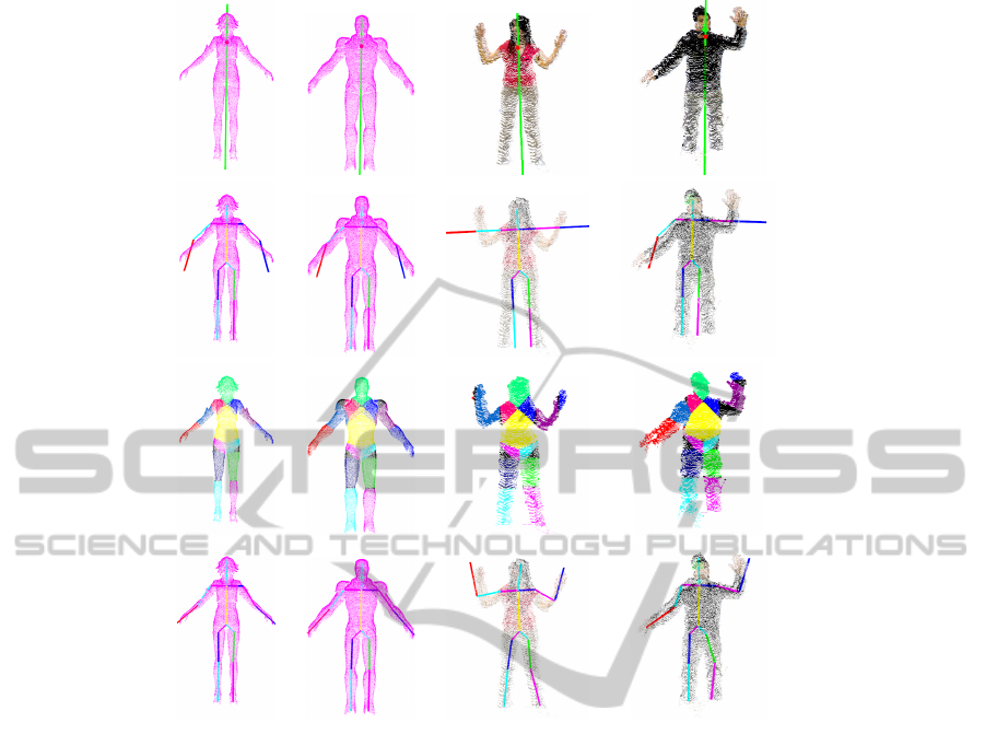
Figure 4: Human pose estimation on body-scanned point clouds using both real and synthetic data. 1
st
row, input point cloud.
2
nd
row, initial skeleton model. 3
rd
row, body parts clustering. 4
th
row, approximated skeleton model. 1
st
col., Nilin Combat
dataset. 2
nd
col., Iron Man dataset. 3
rd
col., Jilliam dataset. 4
th
col., Frederic dataset.
recorded using a multi-view sensing system com-
posed by 2 consumer-accessible RGB-D cameras, i.e.,
the Asus Xtion Pro Live camera, with opposed field-
of-views, i.e., with no data overlapping. Neverthe-
less, the relationship between the two cameras was
determined by a calibration step, using the stereo cal-
ibration implementation available in OpenCV (Brad-
ski and Kaehler, 2008). Better registration approaches
based on ICP, bundle adjustment or the combination
of both can also be considered. However, the cur-
rent approach perfectly estimates the human pose on
such a coarse registered point clouds, handling large
portions of missing data as well as registration inac-
curacies. Synthetic data has been generated using V-
Rep (VRE, 2014), a very versatile robot simulator tool
in which the user can replicate real scenarios. A simu-
lated scene has been created to generate the test cases
with four virtual Kinect cameras installed in the top
corners of the virtual scene. It can be observed that
the data is perfectly registered since a full knowledge
of the relationship between the cameras and their cali-
bration parameters is known. Consequently, synthetic
data has been considered as ground truth data in the
next evaluations. All datasets have been voxelized to
account for point redundancy after data registration.
Voxelization stands for a discrete approximation of
3-D objects into a volumetric representation (Garcia
and Ottersten, 2014a).
Some visual results on both synthetic and real
body-scanned datasets are shown in the Fig. 4. The
first row presents the considered datasets highlight-
ing the estimated orientation of the torso (green line)
and the extracted base point (purple dot). Second
row shows the initialization of the predefined skele-
ton model. The clustering of all body parts is shown
in the third row whereas the fitted skeleton model is
shown in last row, from which results the human pose.
In Fig. 5, the estimated poses of the synthetic Bill
model and a real dataset on some selected point-cloud
video frames are shown. These results show that the
method is able to accurately estimate the body pose
of different body configurations of an upright person.
Real-timeHumanPoseEstimationfromBody-scannedPointClouds
557
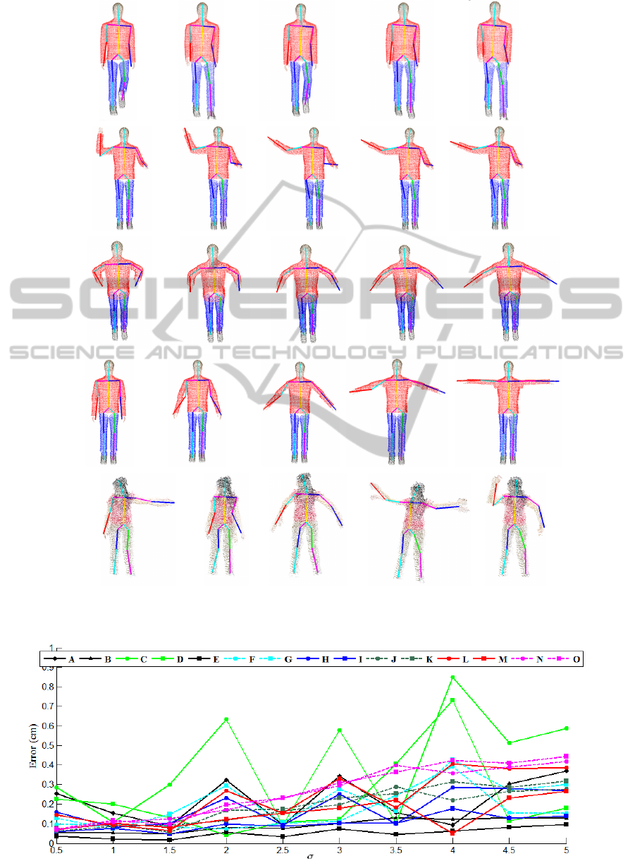
Figure 5: Human pose estimation on different frames from synthetic (1
st
to 4
th
rows) and real (5
th
row) video sequences of
body-scanned point clouds.
Figure 6: Fitting error of skeletal nodes for σ ∈ [0.5,5] cm.
VISAPP2015-InternationalConferenceonComputerVisionTheoryandApplications
558
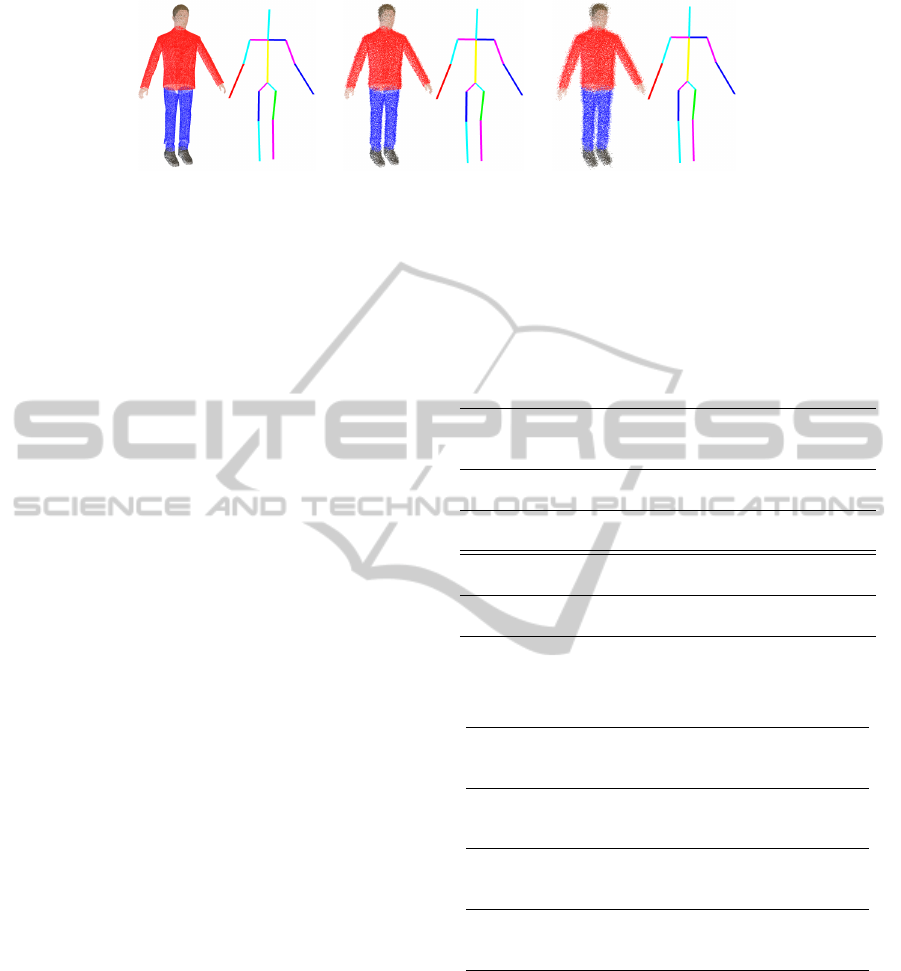
(a) (b) (c)
Figure 7: Bill pose estimation for (a) σ = 0 cm, (b) σ = 2.5 cm and (c) σ = 5 cm.
4.1 Robustness to Noise
Next, the robustness of the current approach against
noise is evaluated. To do so, the synthetic dataset of
Bill has been considered, to which it has been ap-
plied a zero-mean Gaussian noise with standard de-
viation σ ∈ [0.5, 5] cm, i.e., N (0,σ
2
). In order to in-
crease the reliability of this evaluation, the noise has
been added to the depth maps acquired by each vir-
tual Kinect camera, i.e., before being transformed to
point clouds. Fig. 6 depicts the error between the lo-
cation of the resulting skeleton nodes from the noise-
free 3-D model (considered as ground truth), and their
respective ones from the noisy models. The labels of
the nodes correspond to those presented in Fig. 1. As
shown in Fig. 7, the proposed approach is able to es-
timate the Bill pose for all σ values. However, it can
be observed that the fitting error of the skeletal nodes
corresponding to body extremities slightly increases
with amount of noise.
4.2 Runtime and Performance Analysis
Table 1 reports the time consumption to estimate the
human pose for each of the datasets presented in
Fig. 4. Note that most of the time is dedicated to
cluster the 3-D points to estimate the direction of the
torso. However, it is important to recall that this oper-
ation might be done only once in the first video frame,
as discussed in Section 3.
If a better performance is required, one can in-
crease the voxel size to represent the body-scanned
point cloud. Thus, a voxel size of 1 cm
3
has been con-
sidered when evaluating the approach. However, the
performance is significantly increased by increasing
the voxel size, whereas the human pose remains accu-
rately estimated, as shown in Table 2. The only con-
straint of this implementation is that there has to be
a minimum distance of 5 cm between two 3-D points
to be clustered within the same object. Indeed, this
preliminary clustering is performed to cluster each
individual in the scene. Another improvement may
be achieved by parallelizing the initialization of the
Table 1: Time consumption analysis for human pose esti-
mation on the datasets presented in Fig. 4 (units are in ms).
Reported are the mean values taken over 100 iterations. 1
st
row, Nilin Combat dataset (12655 points). 2
nd
row, Iron
Man dataset (21975 points). 3
rd
row, Jilliam dataset (14855
points). 4
th
row, Frederic dataset (19675 points).
Data
Cluster Torso and Initialize Cluster Skeleton
Total
set
3-D torso base point skeleton body limb
time
points extraction model parts fitting
Nilin
226.2 5.0 238.7 47.8 28.0 545.7
Combat
Iron Man 316.8 8.5 412.4 82.1 47.2 867
Jilliam 219.3 5.4 274.5 56.2 30.8 586.2
Frederic 220.2 5.0 275.8 54.7 32.0 587.7
Table 2: Time consumption and robustness depending on
the voxel size to represent the Ironman dataset (units are in
ms).
Voxel
Cluster Torso and Initialize Cluster Skeleton
Error
size
3-D torso base point skeleton body limb
(mm)
points extraction model parts fitting
1 cm
3
316.8 8.5 412.4 82.1 47.2 0.0(21975
points)
3 cm
3
45.4 1.0 66.9 13.2 8.3 1.0(3516
points)
5 cm
3
13.8 0.4 25.3 4.8 3.9 1.8(1305
points)
skeleton model, the clustering of body parts, and the
fitting of the skeleton limbs. Indeed, the human body
can be divided in four different regions, i.e., left and
right arms and left and right legs, that are independent
and thus, can be performed in parallel.
5 CONCLUDING REMARKS
A scheme to estimate the human pose from body-
scanned point cloud datasets has been described. Us-
Real-timeHumanPoseEstimationfromBody-scannedPointClouds
559

ing PCA and prior knowledge on human body pro-
portions, a predefined skeleton model is initialized
and then fitted to the given point cloud by an itera-
tive process based on the theory of Expectation Max-
imization. From the experiments, it is shown that a
good estimate is achieved in both synthetic and real
datasets, and even in the presence of high noise within
the depth measurements. As future work, the current
approach will be extended to alternative body config-
urations other than upright. Alternative techniques to
segment the 3-D points belonging to the torso (used
to estimate its direction) will be further investigated
in order to address the limitations given by the cylin-
drical model, such as the tuning of the model param-
eters.
ACKNOWLEDGEMENTS
This work was partially supported by the National Re-
search Fund, Luxembourg, under the CORE project
C11/BM/1204105/FAVE/Ottersten.
REFERENCES
(2014). Human Proportion Calculator. http://hpc.
anatomy4sculptors.com/.
(2014). Point Cloud Library (PCL). http://pointclouds.org/.
(2014). Virtual Robot Experimentation Platform (V-REP).
http://www.coppeliarobotics.com/.
Au, O. K.-C., Tai, C.-L., Chu, H.-K., Cohen-Or, D., and
Lee, T.-Y. (2008). Skeleton extraction by mesh con-
traction. In ACM SIGGRAPH 2008 Papers, pages
44:1–44:10. ACM.
Bradski, G. and Kaehler, A. (2008). Learning OpenCV:
Computer Vision with the OpenCV Library. O’Reilly
Media, 1st edition.
Cao, J., A., T., M., O., Zhang, H., and Su, Z. (2010).
Point cloud skeletons via laplacian based contraction.
In Shape Modeling International Conference (SMI),
pages 187–197.
Fischler, M. A. and Bolles, R. C. (1981). Random Sample
Consensus: A Paradigm for Model Fitting with Ap-
plications to Image Analysis and Automated Cartog-
raphy. Communications of the ACM, 24(6):381–395.
Garcia, F. and Ottersten, B. (2014a). CPU-Based Real-Time
Surface and Solid Voxelization for Incomplete Point
Cloud. In IEEE International Conference on Pattern
Recognition (ICPR).
Garcia, F. and Ottersten, B. (2014b). Real-time Curve-
Skeleton Extraction from Incomplete Point Clouds:
Application in Human Pose Estimation. In Interna-
tional Conference on Computer Vision Theory and
Applications (VISAPP).
Ke, S.-R., Hwang, J.-N., Lan, K.-M., and Wang, S.-Z.
(2011). View-invariant 3d human body pose re-
construction using a monocular video camera. In
Distributed Smart Cameras (ICDSC), 2011 Fifth
ACM/IEEE International Conference on, pages 1–6.
IEEE.
Lehment, N. H., Arsic, D., Kaiser, M., and Rigoll, G.
(2010). Automated pose estimation in 3d point clouds
applying annealing particle filters and inverse kine-
matics on a gpu. In Computer Vision and Pattern
Recognition Workshops (CVPRW), 2010 IEEE Com-
puter Society Conference on, pages 87–92. IEEE.
Li, M., Yang, T., Xi, R., and Lin, Z. (2009). Silhouette-
based 2d human pose estimation. In International
Conference on Image and Graphics (ICIG), pages
143–148.
Sam, V., Kawata, H., and Kanai, T. (2012). A robust
and centered curve skeleton extraction from 3d point
cloud. Computer-Aided Design and Applications,
9(6):969–879.
Shotton, J., Girshick, R., Fitzgibbon, A., Sharp, T., Cook,
M., Finocchio, M., Moore, R., Kohli, P., Criminisi,
A., Kipman, A., et al. (2013). Efficient human pose
estimation from single depth images. Pattern Analy-
sis and Machine Intelligence, IEEE Transactions on,
35(12):2821–2840.
Tagliasacchi, A., Zhang, H., and Cohen-Or, D. (2009).
Curve skeleton extraction from incomplete point
cloud. In ACM SIGGRAPH 2009 Papers, SIGGRAPH
’09, pages 71:1–71:9. ACM.
Ye, M., Wang, X., Yang, R., Ren, L., and Pollefeys, M.
(2011). Accurate 3d pose estimation from a single
depth image. In Computer Vision (ICCV), 2011 IEEE
International Conference on, pages 731–738. IEEE.
Zhang, L., Sturm, J., Cremers, D., and Lee, D. (2012). Real-
time human motion tracking using multiple depth
cameras. In Intelligent Robots and Systems (IROS),
2012 IEEE/RSJ International Conference on, pages
2389–2395. IEEE.
VISAPP2015-InternationalConferenceonComputerVisionTheoryandApplications
560
