
Large-scale Terrain Level of Detail Estimation based on Wavelet
Transform
Sid'Ali Kalem and Assia Kourgli
USTHB, Faculté d'Electronique et d'Informatique, LTIR, BP32 El_ Alia Bab-Ezzouar, 16111, Algiers, Algeria
Keywords: Large Terrain, Rendering, LOD, View-dependent, GPU, Wavelet, QuadTree.
Abstract: The goal of the following paper is to point out an alternative approach to the adaptive triangulation problem.
A new technique of terrain rendering which uses wavelet transform to select appropriate LOD is described.
This technique is a region-based multi-resolution approach that partitions the terrain into tiles that can be
processed independently. The algorithm organizes the heightmap into a QuadTree of nodes and computes
maximum world-space errors for each node. World-space errors are then calculated at preprocess step. As
the datasets of realistic terrains are usually huge, we suggest using the multi-resolution wavelet
decomposition to localize the position of the maximum world-space error estimated and limit the region of
research inside the node. It permits to choose the appropriate resolution of the regular grid that will
represent the node at run time. By this way, computation load on the CPU is greatly reduced.
1 INTRODUCTION
Over recent years, terrain rendering has been used in
different fields such as movies, virtual
environments, cartography, and games. In particular,
it has been intensively developed for real-time
outdoor games including flight simulators, driving
simulators, and massive multiplayer games. The
rapid development in acquisition of topographic
maps and cartography has led to the generation of
large terrain datasets as height-maps that contain
billions of samples. Such terrains datasets exceed the
rendering capability of available graphics hardware.
Consequently, it is not possible to display 3D scenes
represented by too many details in real-time. Thus,
adaptive Level-Of-Detail (LOD) rendering is used to
simplify the geometry of the heightmap-based
terrain. Usually, LOD rendering algorithms
represent terrains as triangulated meshes which
approximate the surface of the terrain. The challenge
is to efficiently combine quality rendering and real-
time navigation.
The goal of the following paper is to point out an
alternative approach to the adaptive triangulation
problem: the usage of the wavelet transform (WT) as
a mathematical framework which localizes rough
surface approximation where error of the
approximation should be controlled. In some sense,
the WT provides a local spectral estimate of the data
and describes local variations which can be
harvested to govern the coarseness of a surface
mesh.
The organization of the paper is as follows: In
the next section, we give a brief review on terrain
representation techniques. Section 3 is dedicated to
the description of our terrain rendering algorithm. In
the following section, we describe the mathematical
framework of the 2D wavelet transform for surface
and we introduce our main contribution, the
algorithm which determines the appropriate
resolution of the grid based on the wavelet
transform. Section 5 shows the implementation.
Finally, the results of our algorithm are presented in
section 6.
2 RELATED WORK
A number of view-dependent LOD techniques for
terrain rendering have been proposed, which differ
mainly in the hierarchical structure used. Previous
work can be broadly classified into dynamic re-
meshing strategies, region-based multi-resolution
approaches and regular nested grids. All of those
approaches permit continuous LOD rendering of the
terrain geometry.
View-dependent dynamic re-meshing techniques
construct a continuous LOD triangulation in every
258
Kalem S. and Kourgli A..
Large-scale Terrain Level of Detail Estimation based on Wavelet Transform.
DOI: 10.5220/0005310402580264
In Proceedings of the 10th International Conference on Computer Graphics Theory and Applications (GRAPP-2015), pages 258-264
ISBN: 978-989-758-087-1
Copyright
c
2015 SCITEPRESS (Science and Technology Publications, Lda.)
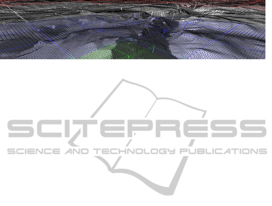
Figure 1: Rendering 3D terrain using regular grid’s meshes of different resolutions.
frame with respect to a given world-space deviation
and screen-space error tolerance. Early approaches
were based on Triangulated Irregular Networks
(TINs) as introduced by Peucker (Peucker T. K.,
Fowler R. J., Little J. J., 1978) and Fowler (Fowler
R. J., Little J. J., 1979) those approaches are well-
known by their approximation quality. Irregular
triangulations minimize the amount of triangles to be
rendered at a given approximation error, but on the
other hand they require quite elaborate data
structures that necessitate an intense CPU
processing. Consequently, more regular
triangulations have been used, for instance, bin-tree
hierarchies (Lindstrom P., Koller D., Ribarsky W.,
Hodges L. F., Faust N., Turner G. A., 1996)
(Duchaineau M., Wolinsky M., Sigeti D. E., Miller
M. C., Aldrich C., Mineev-Weinstein M. B., 1997)
and restricted quad-tree meshes (Von Herzen B.,
Barr A. H., 1987) (Pajarola R., 1998).
Region-based multi-resolution approaches
partition the terrain into tiles that can be processed
independently (Koller D., Lindstrom P., Ribarsky
W., Hodges L. F., Faust N., Turner G., 1995) (Suter
M., Nüesch D., 1995) (Blow J., 2000). To avoid
visual artifacts like popping, either geomorphs are
used (Ferguson R. L., Economy R., Kelly W. A.,
Ramos P. P., 1990) or the maximum screen-space
error is restricted to one pixel. Recent region-based
multi-resolution approaches are based on techniques
that fully exploit the power of modern graphics
hardware. BDAM (Cignoni, P., Ganovelli, F.,
Gobbetti, E., Marton, F., Ponchio, F., and Scopigno,
R, 2003) and P-BDAM (Cignoni P., Ganovelli F.,
Gobbetti E., Marton F., Ponchio F., Scopigno R.,
2003) methods proposed by Cignoni et al exploit
bintree hierarchies of pre-computed triangulations or
batches instead of individual triangles. C-BDAM
method, an extension of BDAM and P-BDAM
algorithms, was presented by Gobbetti et al in
(Gobbetti, E., Marton, F., Cignoni, P., Di Benedetto,
M., and Ganovelli, F, 2006). The method exploits a
wavelet-based two stages near-lossless compression
technique to efficiently encode the height map data.
Terrain rendering method presented by Schneider
and Westermann (Schneider, J., and Westermann, R,
2006) partitions the terrain into square tiles and
builds for each tile a discrete set of LODs using a
nested mesh hierarchy. Following this approach,
Dick et al proposed a method for tile triangulations
encoding that enables efficient GPU-based decoding
(Dick, C., Schneider, J., and Westermann, R., 2009).
Refer to a nice survey by R. Pajarola and E.
Gobbetti (Pajarola, R., and Gobbetti, E., 2007).
Losasso and Hoppe (Losasso F., Hoppe H.,
2004) even show that re-meshing can completely be
avoided by using a set of nested regular grids
centered about the viewer. As the grid resolution
decreases with increasing distance to the viewer,
approximately uniform screen-space resolution is
achieved. This technique caches the terrain in a set
of nested regular grids centered about the viewer.
Asirvatham and Hoppe further improved this
technique in (Asirvatham A., Hoppe H., 2005) to
handle most of computations on the GPU.
Thus, techniques proposed in (Losasso F., Hoppe
H., 2004) (Asirvatham A., Hoppe H., 2005) depend
only on camera position and do not take into account
local surface characteristics. We still believe that
local surface characteristic is an important
component of 3D terrain rendering process, since
different datasets have different characteristics that
should be automatically taken into account to
guarantee the quality of the rendering. Settings used
for terrain rendering should be carefully chosen to
match terrain dataset characteristics while providing
the best performance. In this context, we propose
new technique of LOD estimation based on multi-
resolution wavelet decomposition that permits to
adapt 3D terrain rendering process according to local
surface characteristics in order to reduce
computation load on the CPU.
3 ALGORITHM DESCRIPTION
Our algorithm is a region-based multi-resolution
Large-scaleTerrainLevelofDetailEstimationbasedonWaveletTransform
259
approach which partitions the terrain into tiles that
can be processed independently as illustrated in
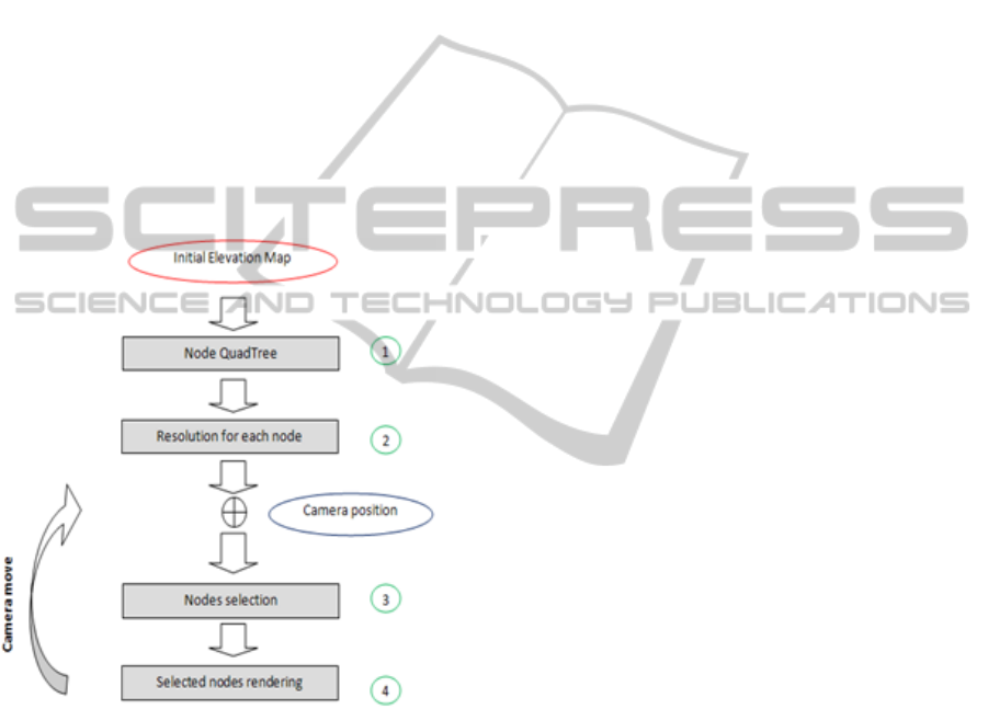
Figure 1. The concept of the rendering method is
illustrated in Figure 2.
First, the algorithm organizes the heightmap into
a QuadTree of nodes, which is used to select
appropriate nodes from different LOD layers at run
time, as illustrated in Figure 3. The algorithm is
based on QuadTree as spatial subdivision scheme.
The QuadTree hierarchy does not store any
geometry; instead it stores the position and
dimension of each node with respect to the terrain.
The QuadTree structure is generated from the input
heightmap. It is of constant depth, predetermined by
memory and granularity requirements. Once created,
the QuadTree does not change unless the source
heightmap changes. In the QuadTree structure every
node has four child nodes and it covers four times
more area than one of its children.
Figure 2: Terrain rendering algorithm.
In the second step, the algorithm computes
maximum world-space error for each node of the
QuadTree. Object-space error is independent from
the metric used and can be computed directly from
the finest resolution grid. World-space errors are
calculated at pre-process. They are used to select the
appropriate resolution of the regular grid which will
represent at run time the node. As the datasets of
realistic terrains are so big, we use the multi-
resolution wavelet decomposition to localize the
position of the maximum world-space error and limit
the region of research inside the node, which is the
main contribution. As a result, we reduce
computation load on the CPU. Since the heightmap
is organized as QuadTree of nodes, we can calculate
only appropriate resolutions of nodes of the lowest
level in the QuadTree and afterwards deduce
resolutions of their parents.
The resolution of the regular grid chosen must
guarantee the quality of the triangulation
approximation of the node. So, the resolution of the
grid to be used for each node of the terrain at run
time is stocked in the structure QuadTree.
At run time, the third step of the rendering
process is the QuadTree nodes selection. It is
performed every time the observer moves, which
usually means during every frame. The LOD of
nodes corresponds to the QuadTree depth level (area
covered) of the nodes and the regular grid’s
resolution used to render the node. The selection is
performed according to the distance between the
node and the camera. At this stage we also perform
view-frustum culling that eliminates the rendering of
non-visible nodes. In order to know which nodes to
select where, distances covered by each QuadTree
layer are pre-calculated before the node selection
process is performed. The array of distance ranges is
thus created which it is also used to create an array
of world-space error tolerable at each layer of the
QuadTree. The array representing the world-space
error tolerable in each range of distance will help us
to choose the resolution of the regular grid for nodes
of the QuadTree.
The actual rendering is performed in step four by
rendering areas covering selected nodes using
regular grid-meshes of different resolution, reading
the heightmap in the Vertex Shader, and displacing
the mesh vertices accordingly, thus forming the
representation of the particular terrain patch.
Commonly used grid-mesh dimensions are 8x8,
16x16, 32x32, 64x64 or 128x128, depending on the
required output complexity.
4 RESOLUTION ESTIMATION
The main contribution is the idea of using the
wavelet coefficients to quickly identify tile sub-
regions that contain the largest world-space error.
Thus, we present a new method for adaptive surface
meshing which selects the appropriate resolution of
the regular grid-mesh by local estimates. The latter
are determined by a wavelet representation of the
(
,
)
=
∑∑
+
∑
,
,
+
,
,
+
,
(1)
GRAPP2015-InternationalConferenceonComputerGraphicsTheoryandApplications
260
surface data. So, the thought is to decompose the
initial data set by wavelet transform WT and to
analyze the resulting coefficients. In surface regions,
where the partial energy of the resulting coefficients
is high, fine grain details are localized, and
consequently, the maximum of world-space error is
also localized and can be calculated. This approach
employs the WT to expand the data and the
amplitude of the detail signals is taken as a measure
of the local frequency. Applying wavelet transform
allows an elegant and fast estimation of the local
level of detail needed.
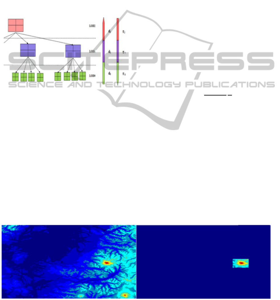
Figure 3: Height-map organized as a QuadTree of nodes,
and corresponding arrays of distance ranges and elevation
tolerable errors.
Any finite energy function f(x,y) ∈L
2
(R
2
) can be
approximated by the bases elucidated above.
c
m
pq
denotes the coordinate of ƒ in functional
space with respect to the wavelet ψ
2,1
mpq
, i. e.
=
〈
,
〉
(2)
The localization of the maximum world-space
error inside the node by detail signals of wavelet
decomposition decreases the computation. Instead of
researching the maximum world-space error over the
entire node, this limit the region of research to
already localized fine grain details as illustrated in
the figure. 4. We will see in section 6 that the
accuracy of the localization depends on the type of
the wavelet used to decompose the heightmap.
It is clear that, we can now formulate a simple
criterion for the maximum of world-space error by
introducing a threshold τ. Increasing τ will result in
increasing the error bounds of the approximation and
decreasing τ will decrease the approximation error.
According to the maximum of elevation errors of
each node of the QuadTree, and by comparing this
maximum with τ we can select the appropriate
resolution for the regular grid to guarantee the
quality of surface approximation of nodes.
According also to the array of distance ranges pre-
computed (Figure 3), the threshold tolerated for each
range of distances is calculated by the formula (3).
Thus every layer of the QuadTree has its threshold.
The quality of the approximation is guaranteed
by the use of a maximum screen space error. Screen
space error is derived at run time from a patch
bounding volume and its world-space geometry. To
approximate screen space error of the node we use
the following equation:
=
(/)
(3)
Where S is the screen resolution (maximum of
horizontal and vertical resolutions),
γ is the field of
view angle,
ε is the node geometric world space
error calculated at preprocess stage, and d is the
distance from the camera to the bounding box.
Since node approximations provide guaranteed
world-space error bound, the given formula provides
guaranteed screen-space error bound of the node.
During the pre-process we increase the grid
resolution for the regions with screen space error
greater than defined threshold and decrease it where
it does not introduce intolerable error. This simple
top-down algorithm generates adaptive
approximation which satisfies user-defines screen
space error threshold.
Figure 4: Localization of the regions of maximum object-space error through wavelet decomposition inside a node.
Large-scaleTerrainLevelofDetailEstimationbasedonWaveletTransform
261
5 IMPLEMENTATION
The implementation of terrain rendering is written in
C++, using DirectX9 as the graphical API and
HLSL. It should work on most GPUs that support
vertex Shader texture sampling, ones supporting
Shader Model 3.0.
To best exploit power of modern GPUs we cache
data of terrain elevations in the fast GPU video
memory and use it across successive frames. CPU
performs QuadTree traversal and selection of
appropriate LOD for different areas of the terrain
based on node geometric world space error and
distance to camera. CPU also performs view-frustum
culling. Thus slow data transfer between CPU and
GPU occurs very rarely.
6 RESULTS AND DISCUSSION
For the following, we investigate the best type of
wavelet function, used to decompose the elevation-
map, to localize regions of maximum world-space
error. We test several types of wavelet functions
such as Haar, Daubechies and biorthogonal wavelet.
We use the dataset “Puget Sound” 16385×16385
height map sampled at 10 meters spacing, which is
used as the common benchmark, with no normal
map, no dynamic lighting, no detail map, and an
overlay color map with embedded lighting. The
dataset is large enough for realistic profiling of
performance. Nodes used for measures are nodes of
low level of the QuadTree that have 1025 × 1025
size. We investigate choice of the type of wavelet
function, used to decompose the elevation-map,
which most closely matches the surface
approximation.
6.1 Maximum World-space Error
Estimation
One of the main advantages of our method is the low
algorithmic complexity for both computation of the
respective transforms and for the QuadTree
meshing. The localization of the maximum world-
space error inside the node by D2WT benefits from
dyadic scaling and sparsity and requires only O (N
2
)
computations. The localization allows us to avoid
computing world-space error inside the entire node,
but focus the computation on the fine grain details
region as illustrated in figure. 4.
Table 1. depicted the substantial gain in
computation loaded on the CPU to compute the
Table 1: Reduction of computation load on the CPU.
Resolution Window
size
Errors computations
per node
Computation
gain (%)
512 3
2
9 99.9991
256 5
2
25 99.9976
128 9
2
81 99.9923
64 17
2
289 99.9725
32 33
2
1089 99.9
16 65
2
4225 99.6
8 129
2
16641 98.42
maximum world-space errors, in order to select
appropriate resolution for each node. The table
shows the number of error computations performed
per node instead of 1025 × 1025 computations over
the entire node. Furthermore, the table illustrated the
gain in computation compared to computation over
the entire node (1025 × 1025 computations).
We define the estimation error as the ration of
the remaining vertices whose planar approximation
error exceeds the maximum world-space error
estimated by the algorithm:
= M N
⁄
(4)
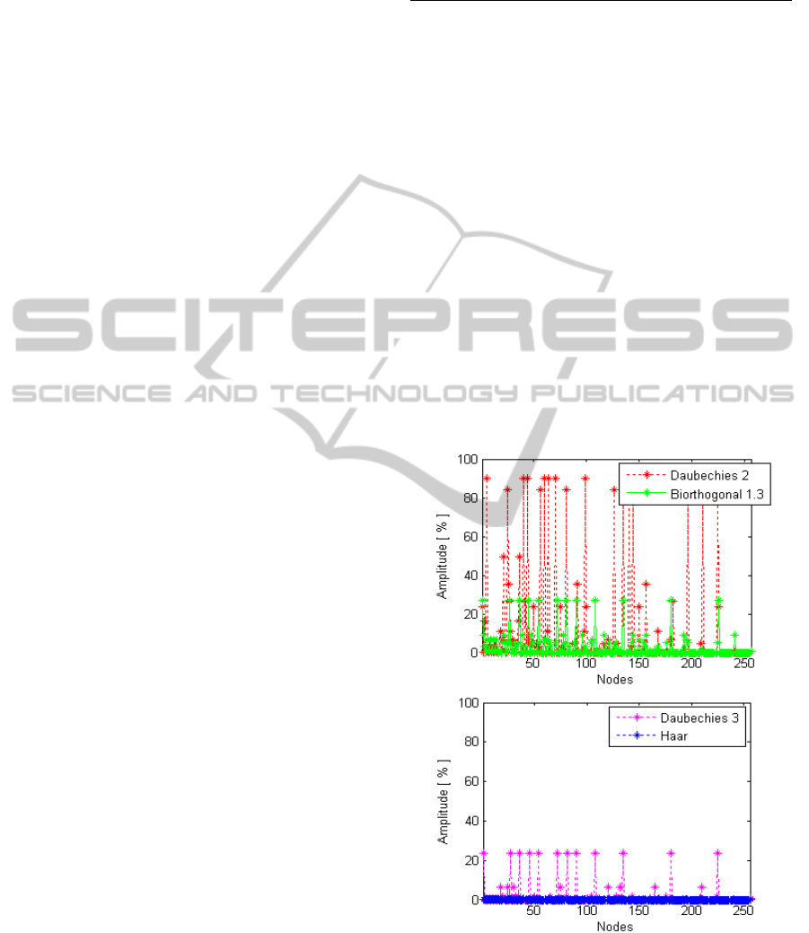
Figure 5: Estimation error per node.
Where N
T
is the number of elevation samples
(1025×1025) per node and M is the number of
elevation samples whose planar approximation error
exceeds the maximum world-space error estimated
GRAPP2015-InternationalConferenceonComputerGraphicsTheoryandApplications
262
by the algorithm. Let f(x,y) be the original surface
and g(x,y) be an approximation. M is the number of
elevation samples f(x
i
,y
i
) that:
∆
(
x
,y
)
=f
(
x
,y
)
−g
(
x
,y
)
>∆
(5)
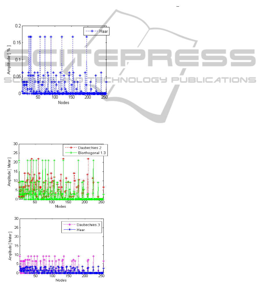
The Figure. 5. illustrates the estimation error per
node of our algorithm for several types of wavelet
function. According to results depicted in Figure 5,
Haar wavelet provides the best localization with
small estimation errors. When we use Haar wavelet
(Figure. 6.), we notice that the estimation error is
negligible and can be interpreted as some kind of
coding gain, depending on the purpose.
Figure 6: Estimation error per node (Haar wavelet).
6.2 Error Analysis of Planar
Approximation
Figure 7: Root of mean square errors of the planar
approximation per node.
One important aspect, when dealing with surface
approximations, is to quantify the approximation
error of the method. In our approach, error
quantification is figured out by the following mean-
square measure. The respective reference value for
the surface f
i
(x
i
,y
i
) is obtained by bilinear
interpolation.
Let f(x,y) be the original surface and g(x,y) be
an approximation. We define the mean-square error
as:
∆
=
∑
∆(
,
)
(6)
where: Δ (x
i
,y
i
) = f(x
i
,y
i
) - g(x
i
,y
i
)
In Figure. 7. the root of the mean-square error is
recorded in meter for each node and for several
types of wavelet functions. We notice that the Haar
wavelet provides the best mean-square error. In the
case of Haar wavelet, we note that the mean-square
error is pretty low for high quality of rendering.
7 CONCLUSIONS AND FUTURE
WORKS
In this paper, we have presented new approach of
selecting LOD based on wavelet decomposition.
This approach uses the wavelet transform as
mathematical framework to localize fine grain
details region where we focus computation which
estimates the maximum of world-space error used to
chooses the appropriate resolution of the regular grid
mesh for each tile of the terrain. This provides a less
expensive method in computation. We also
investigated the best type of wavelet function, used
to decompose the elevation-map, to localize regions
of maximum world-space error. We found that the
Haar wavelet localizes better than other wavelets
regions of maximum world-space error.
In a future work, we will investigate choice of
the type of wavelet function, used to decompose the
elevation-map, which most closely matches the
surface approximation as triangulated meshes.
Details of wavelet decomposition would be used
directly as world-space errors. Moreover, one future
issues of our research is providing an overall
mathematical framework based on wavelet
transform improving the representation of the 3D
height-field geometry in terms of memory cost, time
performance and rendering quality.
REFERENCES
Peucker T. K., Fowler R. J., Little J. J.: The triangulated
Large-scaleTerrainLevelofDetailEstimationbasedonWaveletTransform
263

irregular network. In Proc. ASP-ACSM Symposium
on DTM’s (1978).
Fowler R. J., Little J. J.: Automatic extraction of irregular
network digital terrain models. In Proc.
ACMSIGGRAPH (1979), pp. 199–207.
Lindstrom P., Koller D., Ribarsky W., Hodges L. F., Faust
N., Turner G. A.: Real-time, continuous level of detail
rendering of height fields. In Proc. ACM SIGGRAPH
(1996), pp. 109–118.
Duchaineau M., Wolinsky M., Sigeti D. E., Miller M. C.,
Aldrich C., Mineev-Weinstein M. B.: ROAMing
terrain: Real-time optimally adapting meshes. In Proc.
IEEE Visualization (1997), pp. 81–88.
Von Herzen B., Barr A. H.: Accurate triangulations of
deformed, intersecting surfaces. In Proc. ACM
SIGGRAPH (1987), pp. 103–110.
Pajarola R.: Large scale terrain visualization using the
restricted quadtree triangulation. In Proc. IEEE
Visualization (1998), pp. 19–26.
Koller D., Lindstrom P., Ribarsky W., Hodges L. F., Faust
N., Turner G.: Virtual GIS: A real-time 3D geographic
information system. In Proc. IEEE Visualization
(1995), pp. 94–100.
Suter M., Nüesch D.: Automated generation of visual
simulation databases using remote sensing and GIS. In
Proc. IEEE Visualization (1995), pp. 86–93.
Blow J.: Terrain rendering at high levels of detail. In Proc.
Game Developer’s Conference (2000).
Ferguson R. L., Economy R., Kelly W. A., Ramos P. P.:
Continuous terrain level of detail for visual simulation.
In Proc. IMAGE V (1990), pp. 144–151.
Cignoni, P., Ganovelli, F., Gobbetti, E., Marton, F.,
Ponchio, F., and Scopigno, R. BDAM – batched
dynamic adaptive meshes for high performance terrain
visualization. Computer Graphics Forum, Vol. 22, No.
3, pp. 505–514, 2003.
Cignoni P., Ganovelli F., Gobbetti E., Marton F., Ponchio
F., Scopigno R.: Planet-sized batched dynamic
adaptive meshes (P-BDAM). In Proc. IEEE
Visualization (2003), pp. 147–154.
Gobbetti, E., Marton, F., Cignoni, P., Di Benedetto, M.,
and Ganovelli, F. C-BDAM – compressed batched
dynamic adaptive meshes for terrain rendering.
Computer Graphics Forum, Vol. 25, No. 3, pp. 333–
342, 2006.
Schneider, J., and Westermann, R. GPUFriendly High-
Quality Terrain Rendering. Journal of WSCG, Vol. 14,
pp. 49–56, 2006.
Dick, C., Schneider, J., and Westermann, R. Efficient
Geometry Compression for GPUbased Decoding in
Realtime Terrain Rendering. In Computer Graphics
Forum, Vol. 28, No 1, pp. 67–83, 2009.
Pajarola, R., and Gobbetti, E. Survey on semi-regular
multiresolution models for interactive terrain
rendering. The Visual Computer, Vol. 23, No. 8, pp.
583–605, 2007.
Losasso F., Hoppe H.: Geometry clipmaps: terrain
rendering using nested regular grids. In Siggraph 2004
(New York, NY, USA, 2004), vol. 23 (3), ACM Press,
pp. 769–776. http://research.microsoft. com/~hoppe/.
Asirvatham A., Hoppe H.: GPU Gems 2. Addison-Wesley,
2005, ch. Terrain Rendering Using GPU-Based
Geometry Clipmaps, pp. 27–46.
GRAPP2015-InternationalConferenceonComputerGraphicsTheoryandApplications
264
