
Detecting Objects Thrown over Fence in Outdoor Scenes
Róbert Csordás
1,2
, László Havasi
1
and Tamás Szirányi
1,2
1
MTA SZTAKI, Kende u. 13-17, Budapest, Hungary
2
Budapest University of Technology and Economics, M˝uegyetem rkp. 3, Budapest, Hungary
Keywords:
Optical Flow, Trajectory Matching, Computer Vision, Surveillance System.
Abstract:
We present a new technique for detecting objects thrown over a critical area of interest in a video sequence
made by a monocular camera. Our method was developed to run in real time in an outdoor surveillance
system. Unlike others, we use an optical flow based motion detection and tracking system to detect the
object’s trajectories and for parabolic path search. The system successfully detects thrown objects of various
sizes and is unaffected by the rotation of the objects.
1 INTRODUCTION
Moving object detection is widely used in surveil-
lance systems. We introduce a robust method which
uses a monocular camera system for detecting objects
thrown over a fence in outdoor environments.
The challenge in developing such a method for
outdoor scenes is to detect object trajectories reliably
and to filter out motions that are irrelevant, such as
a person walking or a waving branch of a tree. The
thrown object can be small and blurry, causing some
of the feature extraction based tracking algorithms to
perform poorly.
The method described here is designed to work
with a specific camera placement. The camera should
be placed at the end of the fence, and it should be
pointed exactly to the line of the fence. This would
make the camera capture a whole and clean image of
the area of interest. This criterion is easily met in real
world surveillance scenarios.
Detecting thrown objects by looking at their tra-
jectories can be accomplished easily. They always
follow a parabolic path, even after perspective trans-
formation. After the filtering of the parameters (like
size, length and slope) of the detected parabolic tra-
jectories, the thrown objects can be identified.
Unlike other research in the field, we use optical
flow for finding object trajectories instead of tracking
points of interest. This method is more reliable for
tracking objects that are blurry, small, or have a vari-
able shape. It is also immune to object rotation around
the axis in the image plane that makes the points of in-
terest disappear and re-appear. It can be easily used to
track multiple objects, and it is robust against motions
that are not interfering with the position of the tracked
object.
1.1 Related Work
There are several systems with the capability of de-
tecting thrown objects. These systems are commer-
cial, and their theory of operation is hardly known.
There are very little publicly available studies in this
field; most of the methods are based on motion de-
tection over a dedicated zone, and the path of motion
is not considered. The most related study is (Ribnick
et al., 2007). The authors use an inter-frame differen-
tiating method for identifying areas of rapid motion in
the image. They filter them in advanced ways, keep-
ing track of their centroids, and use expectation max-
imization to find parabolic trajectories. Our method
uses a different way of object tracking which is more
suitable for outdoor use and a different method for
trajectory matching.
The method described in (Venetianer et al., 2005)
uses interesting point detection based object tracking
methods and measures of salience that are not related
to the parabolic trajectories of falling objects.
We use ideas described in (Denman et al., 2009)
to improve the performance and robustness of the al-
gorithm. We use background segmentation methods
to determine the areas of interest, and we run opti-
cal flow on these areas. These areas are usually much
smaller than the area of possible actions, thus reduc-
ing the resources needed for optical flow computation.
The background segmentation also filters out some
593
Csordás R., Havasi L. and Szirányi T..
Detecting Objects Thrown over Fence in Outdoor Scenes.
DOI: 10.5220/0005315505930599
In Proceedings of the 10th International Conference on Computer Vision Theory and Applications (VISAPP-2015), pages 593-599
ISBN: 978-989-758-091-8
Copyright
c
2015 SCITEPRESS (Science and Technology Publications, Lda.)
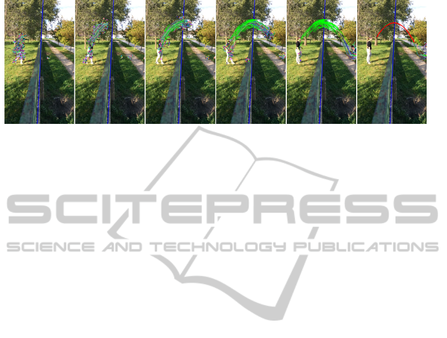
Figure 1: The sequence of a throw and the output of the algorithm.
types of background clutter, which can otherwise in-
terfere with the optical flow algorithm.
2 PROPOSED METHOD
The goal of the project was to reliably detect objects
thrown over a fence. The object can be deformable,
and the algorithm must work in real world applica-
tions. Our method consists of four major steps: frame
capturing and preprocessing, moving point detection,
tracking points, and trajectory matching. The struc-
ture of the system is shown on Figure 4. An example
sequence with the output of the algorithm is shown on
Figure 1.
2.1 Frame Capturing and
Preprocessing
The frame captured by camera is needed to be pre-
processed. Firstly, it is transformed to monochrome
image. The image size is scaled down to size enough
for the accurate operation of the algorithm but yet it
is less resource hungry. The scale is selected so that
the algorithm performs reasonably fast (360x640 pix-
els). A Gaussian blur is applied to the resulting image.
This makes the algorithm more immune to noise and
makes optical flow algorithm perform better.
2.2 Moving Point Detection
After the preprocessing step, the moving points that
are possibly worth tracking are detected. This is done
in two steps.
The first step is foreground segmentation using a
Gaussian mixture-based background/foreground seg-
mentation algorithm (Stauffer and Grimson, 1999).
The resulting foreground map is eroded and dilated
in order to get a rough map of foreground objects
and their close neighborhood. A grid is placed on
the foreground image. In our implementation, the
grid points have a fixed distance, but placing more
points in smaller blobs could possibly increase the
algorithm’s performance on small objects. In some
cases the foreground segmentation step can be omit-
ted. The algorithm performs reasonably well with a
static, fixed grid of points.
After the grid is found, the optical flow is calcu-
lated between the current and the following frame.
This gives a motion vector field. The optical flow is
computed by the Lucas-Kanade algorithm (Bouguet,
2000). In some cases the flow vector is miscomputed
with a large error, which makes the trajectory search
difficult. To filter out most of these errors, the optical
flow is calculated twice: once in forward and once in
backward direction. In backward direction we reverse
the order of frames and use destination points calcu-
lated by the forward step as starting points. If the re-
sulting position vector differs from the initial one by a
certain measure, the flow vector would be considered
invalid.
Figure 2. shows the vector field calculated in this
step. Only vectors with length greater than a thresh-
old (here: min. 1) are shown. The beginning of the
vectors are marked with points.
After the flow is calculated, it is necessary to de-
termine whether a particular point should be tracked.
New points are added to the list of tracked points in
two cases: if there are no tracked points near them,
or if the direction of the flow vector calculated on the
tracked point and the one calculated on the grid dif-
fers. This ensures that there are no unnecessary points
added to the list of tracked points, but also that no im-
portant points are missed. Only points with a certain
flow vector length are tracked. The limits of the vec-
tor length are determined based on the typical speed
of thrown objects in the scene.
VISAPP2015-InternationalConferenceonComputerVisionTheoryandApplications
594
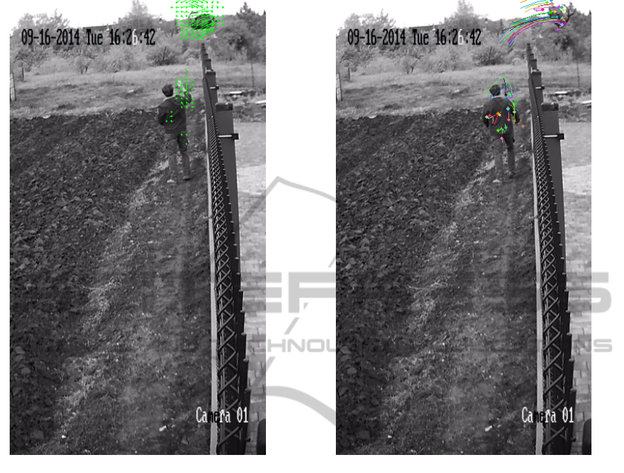
Figure 2: Detected optical flow on the foreground of the
image. Only flow vectors with length greater than 1 are
shown.
2.3 Tracking Points
The moving points detected by the previous step are
added to the list of tracked points. The position his-
tory for every point is kept. At every step, the motion
of the tracked points is calculated with the same dual
direction optical flow algorithm used in the previous
step.
The number of tracked points should be kept low
in order to save resources. Practical constraints are
used to discard inappropriate paths, i.e. long, straight
lines are discarded. The paths which are nearly paral-
lel with the fence are also discarded. The x coordinate
of the path should not change direction. The reason
for this is that the trajectories of the drops should go
either from left to right or from right to left while in
flight. There are some kinds of motions that have near
parabolic trajectories. The best example is a waving
branch. These distractions are also filtered out by this
method.
As a result of the object’s rotation and the vari-
Figure 3: Trajectories of tracked points.
ability of its shape, the tracked points can be lost rel-
atively often. When the track of a point is lost, the
moving point detector detects new motion vectors in
the next frame, and a new tracked point is created.
This results in multiple, shorter trajectories. The tra-
jectory matching algorithm deals with this problem.
Figure 3 shows an example of the motion history
for the tracked points.
2.4 Trajectory Matching
Trajectory matching consists of two separate steps.
The first step finds a large number of relatively small
parabola fractions. This step has a large number of
false positive detections. The second step is to merge
these parabolas into a final parabolic path belonging
to actual thrown objects.
2.4.1 Finding Parabolic Trajectories
The first step is trying to fit parabolas on the trajec-
tories found by the previous step. LS fitting is used
for this: a matrix is built from the coordinates of the
DetectingObjectsThrownoverFenceinOutdoorScenes
595
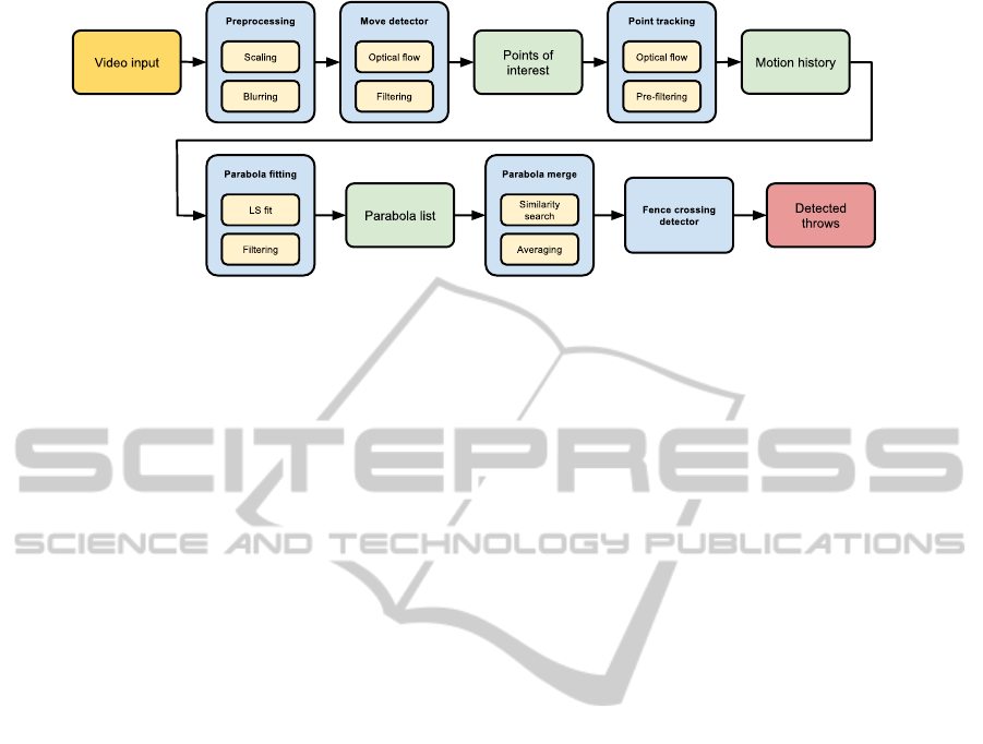
Figure 4: The structure of the system.
points on the path, and the Moore-Penrose pseudoin-
verse (Barata and Hussein, 2012) is taken. From this,
the parameters of the parabola are easy to compute.
Let us assume we have N points along the path. Name
the coordinate pairs belonging to point i x
i
, y
i
, where
i = 1..N. The equation of the parabola is given by:
y
i
= ax
2
i
+ bx
i
+ c (1)
The unknown parameters are a, b, and c. This
equation holds for every point along the path. If we
want to use linear regression, we have to get rid of the
x
2
i
part. Because the value of every x
i
is known, we
can easily rename them to z
i
:
z
i
= x
2
i
(2)
Define matrix X as follows:
X =
z
1
x
1
1
z
2
x
2
1
.
.
.
.
.
.
.
.
.
z
i
x
i
1
.
.
.
.
.
.
.
.
.
z
N
x
N
1
(3)
vector Y
|
as follows:
Y
|
=
y
1
y
2
··· y
i
··· y
N
(4)
and vector P
|
as:
P
|
=
a b c
(5)
Now we want X · P to be close to Y . We are search-
ing for parameters P that give the minimum Euclidean
norm among all solutions:
min
P
||X ·P −Y ||
2
(6)
The solution is the least-square approximation:
P = X
+
·Y (7)
where X
+
denotes the Moore-Penrose pseudoinverse.
The finite length parabolas have two more proper-
ties: their beginning and ending x coordinate. These
are just the x coordinates of the leftmost and rightmost
points in the position history.
After fitting a parabola to the position history, the
square error of the fit is calculated at the points in
the history. They are summed and normalized by the
number of points, giving an error measure that is in-
dependent from the number of points. If the error is
within certain limits, the trajectory is assumed to be a
parabola.
There are many short trajectories found because
of background clutter or other objects in the scene. To
avoid an unnecessary matching step, the approximate
arch length is calculated prior to the fitting process. If
the length is within certain limits the fit is calculated.
In some cases the paths contain other than
parabolic parts. Most of these situations arise from
the fact that someone throws the object with their
hand. If the camera has a clear sight of the object
during the fling of arm, the points can be tracked be-
fore the object leaves the hand of the thrower. In these
situations the initial part of the path is closer to an arc
of a circle than to a parabola. Nevertheless, the top
part of the trajectory is still a parabola after the object
leaves the hand providing the initial force. In these
situations a simple parabola matching fails because
of a large fitting error. Thus, these situations require
a special treatment: only the part that is most likely
parabolic is cut out from the position history and is
used for a second try of fitting a parabola. Because of
free flight, the highest point of the path is most likely
a part of the parabola. The maximum of the path is
considered as a clear maximum if there are points on
its both sides in x direction. If the maximum of the
path is clear, points in a window of a specific length
centered around the maximum are used. If there is
no clear maximum found, the window is placed at the
end of the path that is closer to the top of the image.
The length of the window can be approximately de-
termined by the frame rate, the average distance, and
VISAPP2015-InternationalConferenceonComputerVisionTheoryandApplications
596

the average speed of a thrown object.
The parabolic trajectories that belong to a thrown
object must be oriented in the right direction: they
must have a maximum and not a minimum. There-
fore, the parameter a should be positive (if the origin
is in the bottom left corner). There is also a certain
upper limit for this parameter, because the parabola
cannot be very narrow. This helps to filter out some
false detections.
The parabolas which passed all the tests are saved
in a queue. The parameters a, b, c, x
start
and x
stop
are
saved, along with the frame index of the detection
which serves as a timestamp. x
start
and x
stop
defines
the x coordinates of the ending points of the parabola.
Figure 5 shows an example of detected parabolas
after throwing a backpack through the fence.
Figure 5: Parabolas found based on the motion history of
tracked points.
2.4.2 Merging Trajectories
The final step of the algorithm is run once a parabola
of a certain age is present in the list of detected
parabolas. Age is determined by the associated frame
index of the parabola. This introduces a small delay
before the algorithm produces its final output, but it
also allows for all the parabolas related to a single
drop to be merged together. The delay is about 1 sec-
onds.
The main function of this step is to find similar-
ities in the list of detected parabolas. In order to do
this, a measure for parabola similarity must be de-
fined. The parabolas that look similar and are near
each other should be merged. For this, three major
conditions must be met: First, the maximums of the
parabolas (which are points (x
max,i
, y
max,i
)) should be
near each other. The limit for the distance is deter-
mined in an empirical way. Second, the a parameters
should be close. Third, their base must overlap. The
base of a parabola is defined as the range of x values
under the arc of the parabola. This criterion is easy to
meet when an object is thrown: there are many par-
allel parabolas, so it is very unlikely that they are all
disconnected in such way that no bases overlap. Yet,
it helps a lot to prevent false alarms when the line of
the fence is taken into account. The reason for this is
that the starting and ending points are more certain.
The algorithm does the merging process in two
passes, and uses heuristics for faster and easier imple-
mentation. After a parabola old enough is found, the
search begins for parabolas similar to it. The average
of their maximum and their a parameter is calculated.
The second pass uses these values to find a final set of
parabolas. This eliminates the error that could arise
when a the oldest parabola is one with a misdetected
placement.
When similar parabolas are found, they are aver-
aged, and the final trajectory is found. The set of sim-
ilar parabolas are removed from the list.
After the final trajectory is found, an additional fil-
tering step is applied. The starting and ending point of
the parabola is connected with a straight line, and the
absolute value of the angle of the line is checked. If
the angle is too big, the parabola is highly asymmetric
and is discarded.
2.4.3 Considering the Line of the Fence
If we know the line of the fence, the performance of
the algorithm can be improved. In our case, we tuned
the parameters of the algorithm so that it gives more
false positive matches than false negatives. There is
normally no motion that crosses the line of the fence.
So if the detected parabola crosses the line of the
fence, we can be certain that an object is thrown. Note
that the line of the fence itself is not enough to make
the decision: the parabola detection is important for
filtering out a false event such as birds flying above
the fence, or a branch of a tree wiggling in the breeze.
In steady camera surveillance systems the line of
the fence is well known. The algorithm checks for
line crossing by checking if the starting and ending
points of the parabolas are on the opposite side of the
line assigned to the fence. If they are, the trajectory
is classified as a trajectory of a thrown object, and an
event is generated.
Figure 6 shows the trajectory of the backpack.
Bold red parabola is the final match.
3 EXPERIMENTS
We were able to successfully detect thrown objects in
DetectingObjectsThrownoverFenceinOutdoorScenes
597
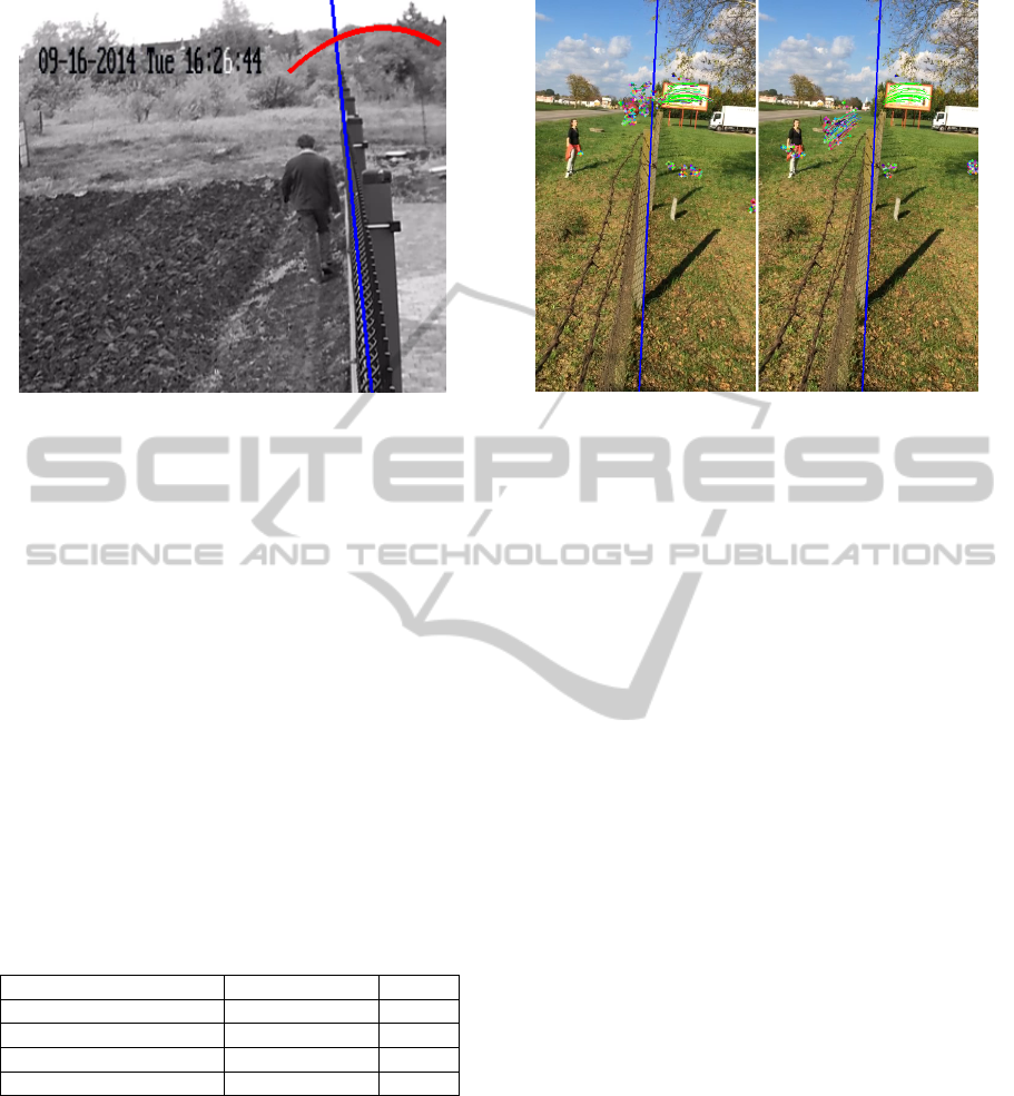
Figure 6: The detected trajectory of the thrown object.
outdoor scenes. We have not found any publicly
available test sets to directly compare our solution
with those of others. The existing systems are com-
mercial, and there are no public test sets available.
We made our own test set, which is available at
http://almafa.org/xdever/FenceTestSets.zip. For reli-
able detection the object should have a minimum di-
ameter of 30 pixels, and the stream should have a min-
imal frame rate of 25fps. Note that in the test sets
there are objects with smaller diameters than that.
The precision is close to 100% because consider-
ing the line of the fence and using the parabolic tra-
jectory detection algorithm make false positives very
unlikely.
Recall rates vary from scene to scene. We used 4
different test sets. They are shown in Table 1. The ob-
ject used for deformable tests was a shirt. A backpack
was used as rigid object.
Table 1: Test results (precision close to 100%).
Scene No. of samples Recall
B&W, Rigid 9 90%
Outdoor 1, Rigid 56 83%
Outdoor 1, Deformable 38 73%
Outdoor 2, Rigid 101 48%
Throwing deformable objects also resulted in high
accuracy. In contrast, scene Outdoor 2 performed
poorly. The reason for this was that, on many sam-
ples, the thrown object was very small. Also, there
was an artefact in the background the pattern of which
was very similar to the object.
Figure 7: An example of failure of tracking the object’s
path.
4 CONCLUSIONS
The proposed algorithm performs well in outdoor sce-
narios, better than other methods in indoor environ-
ments (Ribnick et al., 2007). There are, however
some background patterns that can interfere with the
Lucas-Kanade based motion tracker. This could pos-
sibly be improved by Kalman filtering, which needs
further investigation. We were also able to achieve ex-
cellent results with deformable objects. The fusion of
different methods, including tracking-based and op-
tical flow based solutions, should be investigated in
order to provide better coverage of all cases. Pedes-
trian detection (Havasi et al., 2007) and thrown activ-
ity may be merged in a common framework.
ACKNOWLEDGEMENTS
This work has been supported by the EU FP7 Pro-
gramme (FP7-SEC-2011-1) No. 285320 (PROAC-
TIVE project). The research was also partially sup-
ported by the Hungarian Scientific Research Fund
(No. OTKA 106374).
REFERENCES
Barata, J. C. A. and Hussein, M. S. (2012). The moore–
penrose pseudoinverse: A tutorial review of the the-
ory. Brazilian Journal of Physics, 42(1-2):146–165.
Bouguet, J.-Y. (2000). Pyramidal implementation of the lu-
cas kanade feature tracker. Intel Corporation, Micro-
processor Research Labs.
VISAPP2015-InternationalConferenceonComputerVisionTheoryandApplications
598

Denman, S., Fookes, C., and Sridharan, S. (2009). Im-
proved simultaneous computation of motion detection
and optical flow for object tracking. In Digital Im-
age Computing: Techniques and Applications, 2009.
DICTA ’09., pages 175–182.
Havasi, L., Szlavik, Z., and Sziranyi, T. (2007). Detection
of gait characteristics for scene registration in video
surveillance system. IEEE Trans Image Processing,
16(2):503–510.
Ribnick, E., Atev, S., Papanikolopoulos, N., Masoud, O.,
and Voyles, R. (2007). Detection of thrown objects in
indoor and outdoor scenes. In Intelligent Robots and
Systems, 2007. IROS 2007. IEEE/RSJ International
Conference on, pages 979–984.
Stauffer, C. and Grimson, W. (1999). Adaptive background
mixture models for real-time tracking. In Computer
Vision and Pattern Recognition, 1999. IEEE Com-
puter Society Conference on., volume 2, pages –252
Vol. 2.
Venetianer, P., Lipton, A., Chosak, A., Frazier, M., Haering,
N., Myers, G., Yin, W., and Zhang, Z. (2005). Video
surveillance system. US Patent App. 11/057,154.
DetectingObjectsThrownoverFenceinOutdoorScenes
599
