
Vehicle Tracking and Origin-destination Counting System for Urban
Environment
Jean Carlo Mendes, Andrea Gomes Campos Bianchi and
´
Alvaro R. Pereira J
´
unior
Departamento de Computac¸
˜
ao, Universidade Federal de Ouro Preto, Ouro Preto, Minas Gerais, Brazil
Keywords:
Tracking, Optical Flow, Vehicle Counting.
Abstract:
Automatic counting of vehicles and estimation of origin-destination tables have become potential applications
for traffic surveillance in urban areas. In this work we propose an alternative to Optical Flow tracking to seg-
ment and track vehicles with scale/size variation during movement known as adaptive size tracking problem.
The performance evaluation of our proposed framework has been carried out on both public and privacy data
sets. We show that our approach achieves better origin destination tables for urban traffic than the Optical
Flow method which is used as baseline.
1 INTRODUCTION
The increasing availability of traffic surveillance and
high performance video processing hardware opens
up exciting possibilities for tracking traffic analysis
under computer vision techniques (Buch et al., 2011).
Traffic surveillance availability has been one of the
main issues in video capturing because the amount of
data makes manual analysis unworkable.
Some authors report studies using a tag-based ve-
hicle information, such as global positioning satellite-
GPS (Fleischer et al., 2012) or tag-based vehicle
(Fawzi M. Al-Naima, 2012). However tagged track-
ing presents privacy-related problems since personal
identification is possible and because vehicles re-
quires installation of sensors. On the other hand, com-
puter vision methodologies provide an anonymous
vehicle tracking, avoiding problems concerning pri-
vacy and sensor installation.
Computer vision systems are very attractive for
such purpose as their cost is low compared to other
methodologies. Although several manuscripts de-
voted to present systems for tracking vehicles in a
scene, there are still lots of challenges involved in the
whole process.
Urban traffic is more challenging than road traffic.
Besides data overload and illumination conditions, ur-
ban traffic presents a higher rate of vehicles, frequent
total or partial occlusions and environmental variation
in image capturing. In Figure 1 we show sample
frames of our urban environment.
Many authors have been suggested solutions for
traffic situations such as automatic detection and
tracking of vehicle in an urban traffic approach, as
well as vehicle turning movement counts and genera-
tion of origin-destination trip tables.
In this paper, we show an automatic vehicle track-
ing and turning movement counting system for ur-
ban environments. In our approach, multiple moving
objects are initially segmented from background us-
ing a background-subtraction technique (Stauffer and
Grimson, 1999). Sequently, each segmented region
receives a label. Then tracking begins using a mod-
ified version of Optical Flow approach. The track-
ing methodology was modified to include vehicle size
variation during movement as Optical Flow doesn’t
deal with variation in size. Lastly, moving objects
are tracked and an origin-destination table is gener-
ated and compared with ground truth. The tracking
approaches were tested on real video scenes of ur-
ban traffic under different light conditions, poor im-
age quality, intense traffic, presence of static fore-
ground objects, vehicles of different categories, and
occlusion.
The paper is organized as follows. We begin with
a discussion on related work in Section 2. In Section
3, we discuss the proposed methodology for tracking
vehicles in urban environments, from ROI initializa-
tion, background extraction, blob analysis, and the
strategy for computing a modified Optical Flow track-
ing for vehicles. Section 4 provides experimental de-
tails of vehicle counts turning movements for two dif-
ferent approaches and a description of video database
in Section 4.1. Section 5 concludes and brings a
600
Mendes J., Gomes Campos Bianchi A. and Júnior Á..
Vehicle Tracking and Origin-destination Counting System for Urban Environment.
DOI: 10.5220/0005317106000607
In Proceedings of the 10th International Conference on Computer Vision Theory and Applications (VISAPP-2015), pages 600-607
ISBN: 978-989-758-091-8
Copyright
c
2015 SCITEPRESS (Science and Technology Publications, Lda.)
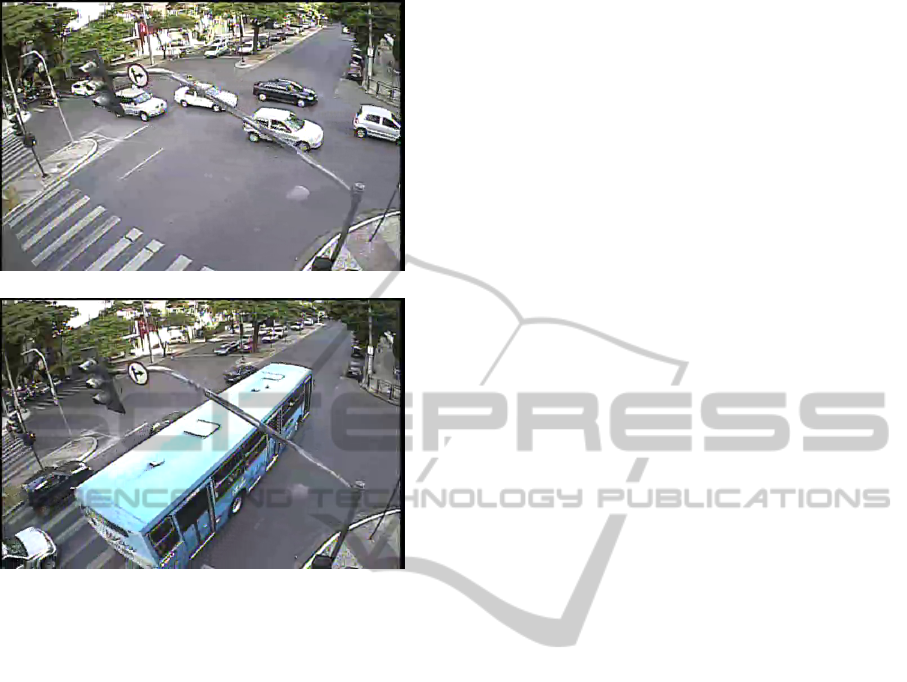
(a) High-Traffic
(b) Occlusion
Figure 1: Video frames of urban environment. Observe high
traffic (a), presence of occlusion (b) and foreground static
objects, size variation, relative size variation because move-
ment, lack of image quality.
summary of our research and suggests possible future
work.
2 RELATED WORKS
There is a small number of methods designed to de-
termine automatic origin-destination of vehicles in ur-
ban environment. In (Lee and Baik, 2006) authors
present a method based on turning movements where
the vehicle’s trajectory is obtained by using fish eyes
lenses to cover a wide area and then to track it using
a Bayesian tracker combined with a particle filtering
approach.
An urban traffic tracker that uses a combination of
blob and feature tracking was presented in (Jodoin
et al., 2014), where authors extract a blob and track it
along the scene.
A simple technique that performs frame differ-
ence between current frame and a background image
(scene without vehicles) is also employed (Han and
Zhang, 2008). Although this technique presents good
performance, it is not suitable for environments with
frequent light changing conditions.
In (Jodoin et al., 2014) authors show a method
that uses blob analysis and object tracking in urban
environments.
A modified version of KLT
(Kanade–Lucas–Tomasi feature tracker) is shown
in (Xue et al., 2012) where authors constructed a
framework to track multiple objects in a single scene.
In (Roberts et al., 2008) authors show a solution
for urban environments using Harris corner detector
combined with a prediction algorithm to track points
along video frames.
A simple blob analysis was used in (Chen et al.,
2007) to extract vehicles features like area, perimeter,
aspect ratio, and dispersiveness. These features were
used to segment and count a vehicle.
Some methods are based on freeways environment
where problems like occlusion and stationary vehi-
cles are minimized. In (Pe
˜
nate S
´
anchez et al., 2012)
authors presented a method using adaptative back-
ground and a probability function to minimize seg-
mentation errors in freeways environment.
Norbert Buch presents (Buch et al., 2011) a re-
view of the state-of-art computer vision for traffic
video.
3 URBAN ENVIRONMENT
MOTION DETECTION
In this section we present a method for traffic-intense
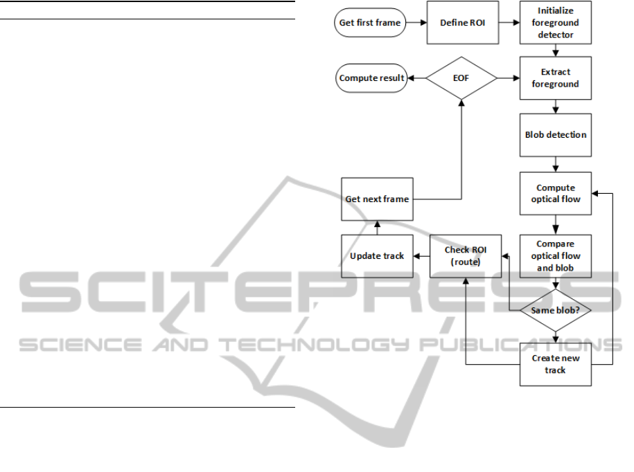
vehicle tracking and origin-destination counting. Fig-
ure 2 presents the components of methodology.
Algorithm 1 presents the method in pseudo-code
in order to highlight the key functions required for an
effective traffic intensive characterization. Compute-
Foreground procedure is used to initialize our fore-
ground detector with the first 1800 frames, which cor-
responds to a one-minute-long video. After this ini-
tial step, the system analyzes each frame updating the
positions of the blobs detected by optical flow tech-
nique (performed by the update TracksOpticalFlow
function) and update a tracking list that contains blobs
tracking positions. If a blob is not visible by a limited
number of frames or if its optical flow points were
not visible anymore, it is removed from list. The lim-
ited number of frames is defined by a threshold. After
these steps the system gets new possible blobs enter-
ing in a scene, gets their features by detecting eigen
features and makes sure object is actually a new one
by comparing it with previously detected tracks.
VehicleTrackingandOrigin-destinationCountingSystemforUrbanEnvironment
601
Algorithm 1: Method algorithm.
1: procedure TRACKING(videoFile)
2: procedure COMPUTEFOREGROUND
3: for integer i = 0; i < numFramesDetector;
i++ do
4: f rame =readNextFrame()
5: f rameF =updateForeground( f rame)
6: end for
7: Return f rameForeground
8: end procedure
9: while videoHasFrame do
10: f rame =readNextFrame()
11: updateTracksOpticalFlow()
12: deleteLostTracks()
13: ob jects =detectObjects( f rame)
14: for each object ob j in ob jects do
15: points = detectMinEigenFea-
tures(object)
16: result = checkIfObjectIsNew(points)
17: updateObjectPosition()
18: checkObjectOverROI()
19: computeResult()
20: end for
21: end while
22: end procedure
3.1 Initialize Region of Interest
When the system is initialized it presents on screen
the first video frame and asks user to mark all region
of interest (ROI). One ROI represents a vehicle’s en-
trance or exit region. This information will be used
for the tracker to determine when a vehicle is counted.
For each ROI, user needs to draw a polygon, create
an ID and inform the type of ROI (’in or out’). When
a vehicle passes over the delimited regions, the sys-
tem uses vehicle ID and origin/target regions IDs to
count it and determine its route. This interface pro-
vides a mechanism that allows user to create and save
a work-region mask. All pixels of the current frame
loaded into the system that is outside work-region
mask is discarded. This step increases the system per-
formance and decreases the number of detected blobs
outside the region of interest.
3.2 Foreground Detection
Foreground detection is a key step in segmentation
and tracking systems by determining which objects
are moving and each ones are stationary. This task
becomes hard when camera’s stability and illumina-
tion conditions change.
One basic approach to detect background is the
Figure 2: System architecture represented in block dia-
grams.
difference between the current frame and the initial
frame without any object. This method is very fast but
requires an initialization and it is not sensitive to light
changes. A better solution is a temporal difference
method that considers a number of time-sequential
frames to calculate the difference. In (Jinglei and
Zhengguang, 2007) authors used the difference be-
tween three sequential frames to calculate a ratio of
changing pixels over the whole difference image and
compared it to a threshold to determine whether it is
a background or not.
The videos used in our work were obtained by a
camera mounted over a traffic light pole that swings
with wind. To minimize effects of camera shake and
light changes in foreground detector an implementa-
tion of Gaussian Mixture Models (Stauffer and Grim-
son, 1999) (Friedman and Russell, 1997) was ap-
plied. In this approach, background model is adapted
in each subsequent frame according to pixels taken
by a mixture of Gaussians. Analyzing the variance of
Gaussians of the mixture for a pixel it is possible to
classify each pixel as background or foreground.
The first one thousand eight hundred frames (first
one-minute video) are used to train foreground de-
tector. This large number is due to hard traffic and
camera instability; by using a large number of frames
we reduce the number of invalid artifacts detected by
VISAPP2015-InternationalConferenceonComputerVisionTheoryandApplications
602
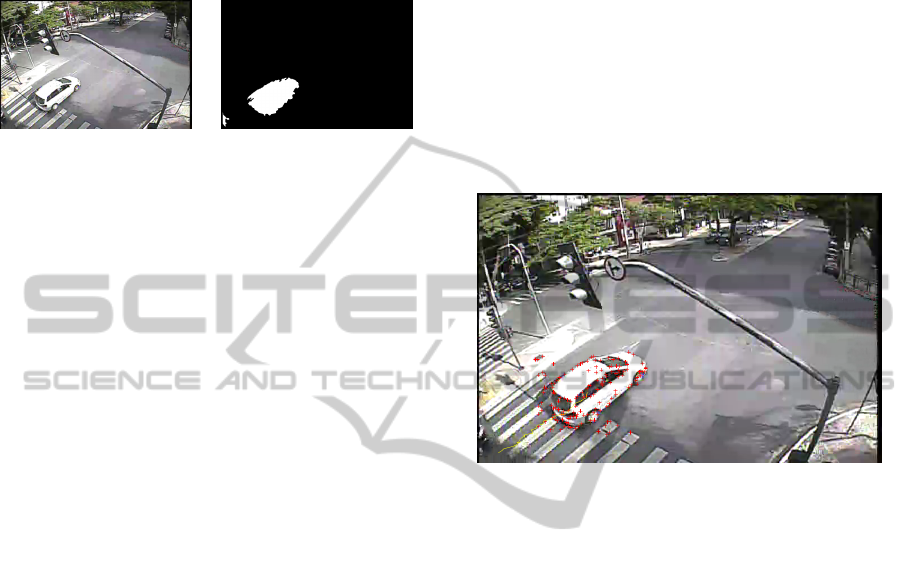
foreground extractor. Foreground model is updated
at each frame computation in the training phase and
used as input for the blob analysis step. In Figure 3
we can find an output sample of system foreground
detector.
(a) Frame (b) Foreground
Figure 3: Foreground detector. Sample frame (a) and Fore-
ground mask (b).
3.3 Blob Analysis
For each object detected by foreground computation,
the system proceeds with a blob analysis that consists
in applying morphological operations (median filter,
closing and hole fills) over foreground result image.
All objects smaller than a threshold (calculated based
on minimum blob area of vehicles found in frames)
are discarded. For blobs regarded as potential vehi-
cles, the system computes area, centroid and bound-
ing box coordinates, as well as a blob label. Blobs
bounding box are used in next steps to calculate re-
gion optical flow and object movement.
Object aspect ratio (width x height relation) is
computed in order to verify whether its values are un-
der an acceptable range to be considered as a potential
vehicle. If it is a potential vehicle, the system creates
a new ID for object and inserts it in a tracker list, used
to keep track vehicle along video frames.
Foreground detector and blob analysis fail when
two vehicles are moving close to each other creating
only one blob for two objects. This issue is solved by
using a K-means segmentation (with k equal 2) un-
der each blob. This creates two region-groups of pix-
els. By comparing the distance between centroid of
this two region-groups, the system can decide if it is a
unique blob or if it contains two vehicles moving to-
gether. On the other hand, in some cases foreground
detector/blob analysis fails by separating one object
in two blobs. To solve this problem, when more than
one blob is found by foreground detector in the same
frame, the system calculates and compares distances
between all pairs of blob centroids. If two centroids
are close enough (determined by a threshold), the sys-
tem will consider that it represents the same object
(and will join it in only one blob). In this case the
blob with older ID will maintain its properties as blob
ID, centroid path, etc.
3.4 Modified Optical Flow Computation
and Tracking
An optical flow computation is performed to deter-
mine movement of blobs detected in previous step.
The bounding boxes of blobs detected are used as re-
gion delimiter to find feature points using eigenvalue
as presented in (Shi and Tomasi, 1994). These fea-
ture points are compared with values calculated in
previous frames and determines if object is already
detected and if object is moving. An example of fea-
ture points of a moving object can be viewed as red
crosses in Figure 4.
Figure 4: Optical flow - Corner features.
Our camera was mounted in one corner of the in-
tersection. This means that we have a high difference
in vehicles size along scene (vehicles far from cam-
era position are clearly smaller than vehicles near the
camera).
Sparse optical flow algorithm, like Lucas-Kanade,
calculates pixels displacement between frames as-
suming local smoothness. If object changes their
sizes along frames, optical flow fails since some
points disappear (when object moves away from cam-
era position) and some appear (when object moves to-
ward the camera). The object points reacquisition is
necessary along the video frames. This is performed
by comparing optical flow points from previous frame
with object detection (foreground detector result) in
current frame.
If result of optical flow computation is higher than
a percentage of feature points detected (determined by
a threshold with value equal 55), object tracker is up-
dated by computing new points position and new cen-
troid position. This task is necessary because when an
object position changes along video frames, its size
and aspect ratio also changes and causes lost points.
A vector containing centroid path is saved to show
vehicle route to user as seen in Figure 5. At this mo-
ment vehicle’s age is incremented to label number of
frames in which this vehicle is tracked as shown in
VehicleTrackingandOrigin-destinationCountingSystemforUrbanEnvironment
603
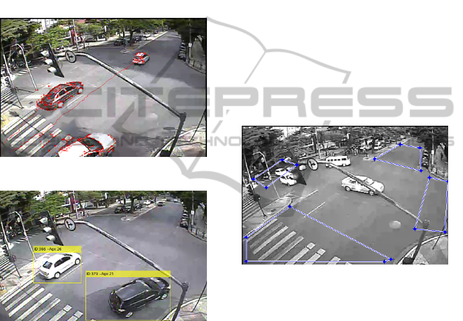
Figure 6. If the result of the optical flow computation
is lower than a threshold, object is considered not vis-
ible in current frame and its property called Consec-
utive Invisible Frames is incremented. When object
is not visible in more than eight consecutive frames,
it is discarded. Considering medium vehicle size and
medium speed of objects, eight frames represent a dis-
tance equal to vehicle size. By discarding objects in-
visible for eight frames the system avoids recognizing
a new vehicle at same position as the old one that is
invisible.
Figure 5: Centroid Path/Route computed by tracking
methodology.
Figure 6: Vehicle ID and age computed by tracking method-
ology.
3.5 Creating New Objects
Because vehicles are entering and leaving video area
all the time, the system needs to detect possible new
objects and decide whether it is a new detection or an
existing moving object detected in previous frames.
To perform this task, after detecting foreground, the
system takes all blobs in current frame and compares
its positions to positions of blobs detected in previous
frames (number of previous frames used in this com-
parison is determined by a threshold). If the centroid
of new detection is close enough (determined by a
threshold) to some object detected in previous frames,
they are considered same object and its properties are
updated. Otherwise, a new object is created and it re-
ceives a new ID. This new object is included in object
detect vector and will be tracked and analyzed again
in the next frame.
3.6 Region of Interest Analysis
When an object centroid passes over a region of in-
terest, ROI ID and region type (in/out) are saved into
object properties. This ID will be used along the vehi-
cle’s lifetime over next frames to determine its route.
At this moment, object ID is stored in a result set
to prevent duplicate in counting. This is necessary
because ROI is a polygon (not a single line) and an
object will pass over the region in multiple sequen-
tial frames. Therefore, when a object passes over a
ROI its ID is compared with all IDs that have already
passed over a polygon region and will be computed
only on its first detection over the region. Figure 7
shows a frame with a user defined ROI
Figure 7: Frame ROI.
3.7 Compute Results
When an object passes over a ROI of type ’out’, its
route is computed based on origin and destination
regions identifications (IDs) stored in its properties.
If an origin-destination pair is already presented in
the result set, this value is incremented; otherwise,
a new result entry is created. This step is executed
along all video frames and when the end of the file is
reached, the system shows a table containing Origin-
Destination identification with the total vehicle count.
4 EXPERIMENTS
In this section we present the dataset used and the ex-
perimental results.
VISAPP2015-InternationalConferenceonComputerVisionTheoryandApplications
604
4.1 Video Database
Three video sequences were taken in an urban inter-
section in three different times of a given day. All
sequences were captured by the same camera at 30
frames per second and frame size of 720x480. First
and second sequences were taken in daylight con-
ditions and third sequence at the end of afternoon.
Video length and total vehicles in each sequence can
be seen at Table 1 where Vehic. (A) and Vehic. (B)
are ground truth of vehicle quantities that pass over
each route.
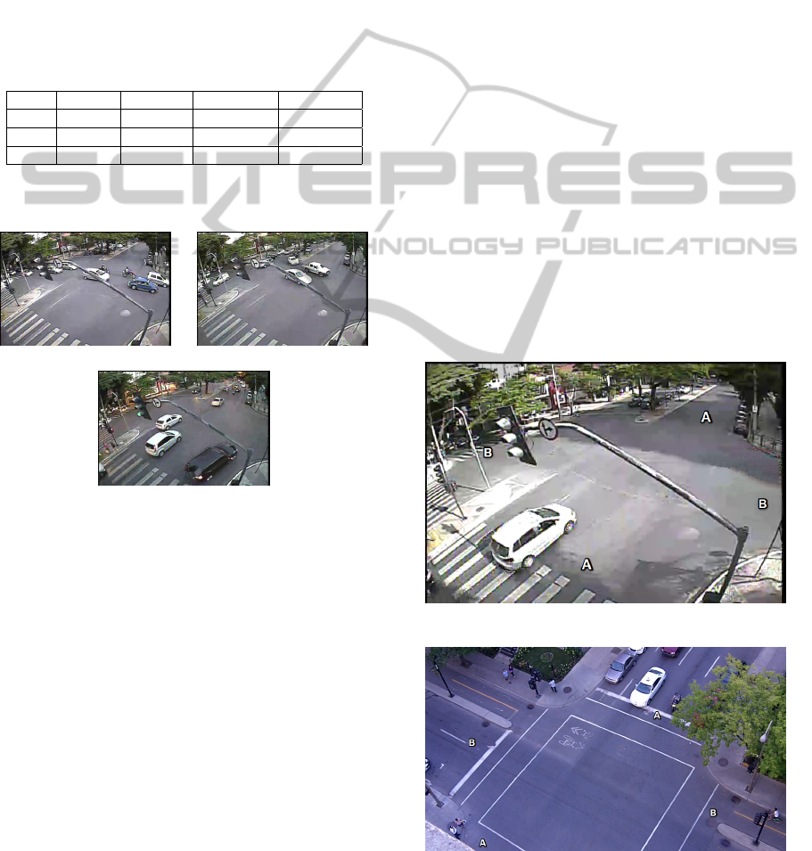
Table 1: Video database details.
Seq. Len. Frames Vehic.(A) Vehic.(B)
01 59:52s 107669 69 112
02 59:59s 107874 81 126
03 60:00s 107893 128 101
In Figure 8 we show some examples of video
frames taken under a range of realistic conditions.
(a) Sequence 01 (b) Sequence 02
(c) Sequence 03
Figure 8: Example frames from video sequences. (a) and
(b) Sunny conditions with shadows and occlusions (c) End
of afternoon with dark scene.
In Figure 9 we can find routes identification for
captured videos and in Figure 10 we can find routes
identification for StMarc video that is a public video
used in (Jodoin et al., 2014). Vehicles entering in
video frame by route B are more distant from the cam-
era position and are occluded by a tree, which causes
difficulties for foreground detection and consequently
object tracking.
All video sequences are available to scien-
tific community on website 4shared.com/folder/
X9pXuxKD/TrafficDatabase.html, as well as the
ground truth table of five-minute segments of each
video. This will help future related works to perform
tests and compare results.
4.2 Results
Experiments were made using two approaches. The
first one used an original implementation of optical
flow using Lucas-Kanade features. Results from ex-
ecution of this approach was used as baseline. Sec-
ond experiment was made using our modified version
of optical flow. Results of both can be seen in Ta-
ble 2 where Prec. , Recall, and F1 respectively stand
for Precision, Recall and F1-Score for original op-
tical flow implementation and Prec. (Mod.), Recall
(Mod.), F1 (Mod.) stand for Precision, Recall and F1-
Score for modified optical flow tracking method. Col-
umn ’Gain F1’ shows the gain in F1-Score of modi-
fied optical flow implementation over baseline.
Sequence A-A presents the best results for preci-
sion in all three sequences, as well as modified optical
flow. Recall and F1 also have high values indicating
that returned values are also relevant. B-B sequence
presents high precision values, but lower recall. Such
behavior may be correlated to video complexity in re-
gards to occlusions and illumination. It is denoted that
the modified version for all sequences and both routes
have better results than the classical version of optical
flow.
The same experiment was done using public St
Marc video sequence and is presented in Table 3.
Figure 9: Route’s IDs.
Figure 10: Route’s IDs - StMarc.
VehicleTrackingandOrigin-destinationCountingSystemforUrbanEnvironment
605

Table 2: Results table - Original and Modified Optical Flow.
Seg./Route Prec. Recall F1 Prec. (Mod.) Recall (Mod.) F1 (Mod.) Gain (F1)
S01/A-A 59.52% 48.10% 53.20% 71.43% 75.47% 73.39% 37.98%
S01/B-B 73.33% 33.00% 45.51% 86.95% 58.25% 69.77% 53.28%
S02/A-A 70.83% 50.07% 59.13% 82.81% 75.71% 79.10% 33.78%
S02/B-B 62.10% 28.97% 39.49% 70.67% 50.96% 59.21% 49.95%
S03/A-A 62.38% 48.50% 54.54% 74.51% 74.51% 74.51% 36.60%
S03/B-B 58.97% 27.06% 37.09% 67.24% 47.56% 55.71% 50.19%
Table 3: Results table - StMarc video.
St Marc
Route Groundtruth System result Accuracy
Route A-A 4 4 100.0%
Route B-B 4 4 100.0%
5 CONCLUSION
We presented a hybrid algorithm that combines opti-
cal flow to track points along video frames and fore-
ground detection to reacquire points and update track-
ing information during size variation of objects in
sequence. This mixed solution allows us to mini-
mize problems caused by changes in object size along
video frames.
It is clear that good results in optical flow using
Lucas-Kanade approach highly depends on quality of
initial object segmentation. If foreground detector
fails, all following approaches will also fail because it
will calculate pixel displacement in wrong positions.
By using a hybrid solution that combines optical flow
results with foreground extraction the error is mini-
mized and system accuracy is increased.
ACKNOWLEDGEMENTS
This work was supported by Fapemig, CNPq and
Capes.
REFERENCES
Buch, N., Velastin, S., and Orwell, J. (2011). A review
of computer vision techniques for the analysis of ur-
ban traffic. Intelligent Transportation Systems, IEEE
Transactions on, 12(3):920–939.
Chen, T.-H., Lin, Y.-F., and Chen, T.-Y. (2007). Intelli-
gent vehicle counting method based on blob analysis
in traffic surveillance. In Innovative Computing, In-
formation and Control, 2007. ICICIC ’07. Second In-
ternational Conference on, pages 238–238.
Fawzi M. Al-Naima, H. A. H. (2012). Vehicle traffic con-
gestion estimation based on rfid. volume 4:30.
Fleischer, P., Nelson, A., Sowah, R., and Bremang, A.
(2012). Design and development of gps/gsm based ve-
hicle tracking and alert system for commercial inter-
city buses. In Adaptive Science Technology (ICAST),
2012 IEEE 4th International Conference on, pages 1–
6.
Friedman, N. and Russell, S. (1997). Image segmentation
in video sequences: A probabilistic approach. In Pro-
ceedings of the Thirteenth Conference on Uncertainty
in Artificial Intelligence, UAI’97, pages 175–181, San
Francisco, CA, USA. Morgan Kaufmann Publishers
Inc.
Han, C. and Zhang, Q. (2008). Real-time detection of vehi-
cles for advanced traffic signal control. In Computer
and Electrical Engineering, 2008. ICCEE 2008. Inter-
national Conference on, pages 245–249.
Jinglei, Z. and Zhengguang, L. (2007). A vision-based road
surveillance system using improved background sub-
traction and region growing approach. In Software
Engineering, Artificial Intelligence, Networking, and
Parallel/Distributed Computing, 2007. SNPD 2007.
Eighth ACIS International Conference on, volume 3,
pages 819–822.
Jodoin, J.-P., Bilodeau, G.-A., and Saunier, N. (2014). Ur-
ban tracker: Multiple object tracking in urban mixed
traffic. In Applications of Computer Vision (WACV),
2014 IEEE Winter Conference on, pages 885–892.
Lee, S.-M. and Baik, H. (2006). Origin-destination (o-d)
trip table estimation using traffic movement counts
from vehicle tracking system at intersection. In IEEE
Industrial Electronics, IECON 2006 - 32nd Annual
Conference on, pages 3332–3337.
Pe
˜
nate S
´
anchez, A., Quesada-Arencibia, A., and
Travieso Gonz
´
alez, C. (2012). Real time vehi-
cle recognition: A novel method for road detection.
In Moreno-D
´
ıaz, R., Pichler, F., and Quesada-
Arencibia, A., editors, Computer Aided Systems
Theory – EUROCAST 2011, volume 6928 of Lecture
Notes in Computer Science, pages 359–364. Springer
Berlin Heidelberg.
Roberts, W., Watkins, L., Wu, D., and Li, J. (2008). Vehicle
tracking for urban surveillance. volume 6970, pages
69700U–69700U–8.
Shi, J. and Tomasi, C. (1994). Good features to track. In
Computer Vision and Pattern Recognition, 1994. Pro-
ceedings CVPR ’94., 1994 IEEE Computer Society
Conference on, pages 593–600.
Stauffer, C. and Grimson, W. E. L. (1999). Adaptive
background mixture models for real-time tracking.
In Computer Vision and Pattern Recognition, 1999.
VISAPP2015-InternationalConferenceonComputerVisionTheoryandApplications
606

IEEE Computer Society Conference on., volume 2,
pages –252 Vol. 2.
Xue, K., Vela, P., Liu, Y., and Wang, Y. (2012). A modi-
fied klt multiple objects tracking framework based on
global segmentation and adaptive template. In Pattern
Recognition (ICPR), 2012 21st International Confer-
ence on, pages 3561–3564.
VehicleTrackingandOrigin-destinationCountingSystemforUrbanEnvironment
607
