
Automatic Waveguide-fiber Alignment Algorithm
based on Polynomial Fitting
Yu Zheng, Baibing Li and Ji-an Duan
State Key Laboratory of High Performance Complex Manufacturing, College of Mechanical and Electrical Engineering,
Central South University, Changsha, 410083, China
Keywords: Optical Waveguide Device, Aligning and Coupling, Coupling Model, Alignment Algorithm.
Abstract: We report on a highly efficient alignment algorithm, which based on coupling model, between an optical
fiber and an optical waveguide device. For 1×16 optical waveguide splitter, many repeated experiments can
guarantee that the insertion loss of the device channels is less than 13.5 dB, with the maximum uniformity
of 0.40 dB.
1 INTRODUCTION
Optical fiber communications has driven the need
for complex photonic integrated circuit (PIC) to
process the massive amounts of data transmitting
through global networks (Yamada et al., 1993;
Zheng and Duan, 2012). As the complexity and
feature size of photonic integrated circuit, automatic
optical alignment has become a key technique for
optical waveguide devices, such as arrayed
waveguide gratings, optical beam coupler/splitters,
optical switchers and variable optical attenuators
(Zheng and Duan, 2009). The core diameter of the
single mode fiber is 8~9 μm, and the optical channel
section feature size of photonic integrated circuit is
0.2~8 μm. Each fiber must be positioned correctly
on the part, and each part must be aligned in six
dimensions (three translational and three angular) to
assure low coupling losses.
Automatic precise alignment coupling is the only
way of improving optical quality for optical
waveguide devices, and is necessary to step into
scientific manufacturing from technological
manufacturing. Alignment coupling algorithm of
optical waveguide chip and optical fibers is premise
of its automatic packaging, and good alignment
coupling algorithm shows in rapid alignment, high
precision and high reliability. Although several
algorithms for the automatic fiber to waveguide
alignment have been developed, such as hill-
climbing algorithm, simplex algorithm, pattern
search algorithm, Hamilton algorithm and genetic
algorithm (Zheng and Duan, 2013a; Zheng and
Duan, 2013b; Tang et al., 2001; Mizukami et al.,
2001; Masahiro et al., 2004; Tseng and Wang, 2005;
Chun et al., 2006), all of these are based on
mathematical optimization algorithm, which make
these extremely sensitive to the disadvantages of
algorithm itself and the precision of motion stages
Zheng and Duan, 2013b). For those reason,
automatic waveguide-fiber alignment algorithm
which based on coupling model, according to the
theory of waveguide-fiber coupling, has been
preferred.
The coupling model and coupling theory of
waveguide-fiber alignment are treated in section 2.
In section 3, the experimental results of automatic
waveguide-fiber alignment based on the new
algorithm, which based on coupling model of
waveguide-fiber alignment, are presented.
2 COUPLING MODEL AND
COUPLING THEORY
Figure 1 is the schematic of waveguide-fiber
Figure 1: Schematic of waveguide-fiber alignment.
77
Zheng Y., Li B. and Duan J..
Automatic Waveguide-fiber Alignment Algorithm based on Polynomial Fitting.
DOI: 10.5220/0005328400770080
In Proceedings of the 3rd International Conference on Photonics, Optics and Laser Technology (PHOTOPTICS-2015), pages 77-80
ISBN: 978-989-758-093-2
Copyright
c
2015 SCITEPRESS (Science and Technology Publications, Lda.)

alignment. Geometric alignment error includes
horizontal dislocation
x
δ
and
y
δ
, angular deflection
α
β
, and
γ
, and longitudinal spacing
d
.
According to Ref. (Zheng and Duan, 2013b), the
coupling efficiency of optical waveguide and optical
fiber is
x
y
η
ηη
(1)
where,
2
22
22 2 2
22
11
exp{ [ ( )
2
[() ]
]}
2
x
xx x
wa f
xa f
x
wa
kk
WW
dW
d
W
δ
η
πβ ω
δβ
λ
=− +
+
⋅⋅
+−
(2)
22
222222
4
()
wa f
x
wa f
WW
k
WW d
λπ
=
++
(3)
22 2
2
() [1 ( )]
wa wa
wa
d
dW
W
λ
ω
π
=+
(4)
where,
f
W
is radius of optical fiber mode field,
wa
W
and
wb
W
are mode field radius of optical waveguide
along the ellipse long and short axes, respectively. In
Formula (2), used
y
in place of
x
,
y
η
can be
obtained. Set
0
α
β
==
and
wa wb
WW=
, for the
given longitudinal spacing
d
and wavelength
λ
,
x
k
is a constant. The insertion loss (
d
I
L
) of one
optical channel is
22
22
10lg 20lg( )
11
10lg [ ( )]( )
2
dx
x
x
y
wa f
IL k
k
e
WW
η
δδ
=− =− +
⋅++
(5)
Thus, theoretically there is quadratic function
relation between insertion loss of alignment
coupling of optical fibers and optical waveguide
chip and horizontal dislocation. The new automatic
waveguide-fiber alignment algorithm is base on the
Formula (5).
3 EXPERIMENT AND RESULTS
3.1 System Architecture
Construct automatic waveguide-fiber alignment
coupling system based on Figure 2. The waveguide
chip (WG chip) was held in a holder unit. The input
and output fiber arrays (FA) were set on 6-axis
precision stages, which line repositioning resolution
was 0.3 μm, and angle repositioning resolution was
0.001°. The machine vision system includes two
orthogonally positioned microscopes with charge-
coupled device (CCD) cameras. Laser source, two-
channel optical power meter, and control box of the
input and output stages were adopted, and they
communicated with the computer via GPIB
connector.
Figure 2: Structure figure of automatic alignment system.
3.2 Experimental Results
Optical waveguide used for alignment coupling is
1×16 optical waveguide splitter, and the adhesion
used for solid joint of coupling interface is index
matching adhesion. Table 1 shows the geometric
dimensioning and material parameter of optical
waveguide splitter. The environment temperature
and humidity were respectively 23℃ and 50%. The
motion velocity was set to 10mm/s, and the target of
Insertion Loss was set to 14dB, as shown in Figure
3.
Table 1: Geometric dimensioning and material parameter
of optical waveguide splitter.
Parameters Units Specification
Length mm 15
Width mm 3.5
Height mm 2.5
Material
Core Silica+GeO
2
Cladding Quartz
Core size μm 8×8
Operational
wavelength
nm 1260~1650
Theoretical
Insertion Loss
dB 12.04
Insertion Loss
(Max.)
dB 13.2
Uniformity dB 0.50
Alignment coupling loss was caused by the process
of device packaging and manufacturing, and it was
related to motion stages, controlling, alignment
PHOTOPTICS2015-InternationalConferenceonPhotonics,OpticsandLaserTechnology
78
algorithm, etc. For 1×16 optical waveguide splitter,
the required time was less than 3 min. According to
Table 2, it can be known that for 1×16 optical
waveguide splitter, many repeated experiments can
guarantee that the insertion loss of the device
channels was less than 13.5 dB, with the
maximum uniformity of 0.40 dB.
Table 3 show the experimental results of
alignment coupling of 1×16 optical waveguide
splitters based on manual stages. The insertion loss
was more than 13.5 dB, and the maximum
uniformity was more than 0.75 dB. The alignment
time was more than 5 min. Such results
demonstrated the effectiveness of the alignment
coupling algorithm which based on coupling model.
4 CONCLUSIONS
We have demonstrated a highly efficient alignment
algorithm, which based on coupling model, between
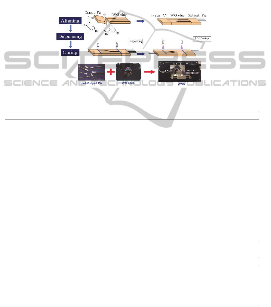
Figure 3: Process of automatic alignment system for waveguide-fiber.
Table 2: The automatic alignment results (Insertion loss, dB).
NO. CH1/9 CH2/10 CH3/11 CH4/12 CH5/13 CH6/14 CH7/15 CH8/16 Avg. Max-Min
1
12.73 12.83 12.84 12.80 12.72 12.71 12.89 12.80
12.78 0.18
12.71 12.75 12.76 12.77 12.71 12.80 12.78 12.80
2
12.82 12.85 12.93 12.87 12.79 13.01 13.07 12.88
12.89 0.32
12.75 12.81 12.84 12.96 12.76 12.95 12.96 12.95
3
12.76 12.75 12.88 12.83 12.98 12.91 12.88 12.83
12.82 0.33
12.65 12.76 12.80 12.88 12.72 12.84 12.81 12.85
4
13.08 13.10 13.02 13.13 13.07 13.14 13.14 13.10
13.12 0.37
13.21 13.10 13.05 13.08 13.39 13.17 13.11 13.08
5
13.00 12.90 12.89 13.10 13.20 12.96 12.94 13.01
12.97 0.37
12.85 12.88 12.90 13.05 13.08 12.89 12.83 12.99
6
12.84 12.72 12.89 12.88 12.86 12.94 12.97 12.92
12.89 0.25
12.82 12.84 12.86 12.93 12.87 12.95 12.95 12.93
7
12.99 12.95 12.95 13.01 13.12 12.97 12.89 13.00
13.00 0.23
13.04 13.02 12.98 13.05 13.05 12.97 13.00 13.03
8
13.11 12.81 12.92 12.85 13.11 12.84 12.88 12.83
12.92 0.30
12.97 12.92 12.92 12.87 12.85 12.86 12.97 12.94
9
12.90 12.91 12.94 12.93 12.88 13.01 13.00 12.92
12.93 0.18
12.92 12.83 12.89 12.92 12.95 12.91 12.97 12.90
Table 3: The automatic alignment results (Insertion loss, dB).
NO. CH1/9 CH2/10 CH3/11 CH4/12 CH5/13 CH6/14 CH7/15 CH8/16 Avg. Max-Min
1
13.25 13.33 13.29 13.36 13.10 13.29 13.74 14.01
13.53 0.95
13.41 13.80 13.54 13.15 14.05 13.54 13.66 14.03
2
13.51 13.50 13.15 13.49 14.02 13.26 13.67 13.45
13.53 0.93
14.08 13.62 13.43 13.25 13.54 13.28 13.85 13.42
3
13.58 13.24 13.40 13.68 13.22 13.24 13.56 13.54
13.50 0.76
13.66 13.54 13.26 13.67 13.36 13.98 13.54 13.58
AutomaticWaveguide-fiberAlignmentAlgorithmbasedonPolynomialFitting
79

an optical fiber and a silica waveguide. For 1×16
silica waveguide, many repeated experiments can
guarantee that the insertion loss of the device
channels is less than 13.5 dB, with the maximum
uniformity of 0.40 dB. High efficiency, high
precision and reliability demonstrate its potential for
multi-channel waveguide-fiber alignment
applications.
ACKNOWLEDGEMENTS
The authors thank for the finical supported by the
National Natural Science Foundation of China
(Grant No. 51475479 and 51075402), the National
High-Tech R&D Program of China (Grant No.
2012AA040406), the Research Fund for the
Doctoral Program of Higher Education of China
(Grant No. 20110162130004), the Natural Science
Foundation of Hunan Province (Grant No.
14JJ2010), and the open project of stage key
laboratory of Fluid Power Transmission and Control
(Grant No. GZKF-201401).
REFERENCES
Y. Yamada, A. Takagi, I. Ogawa, et al, “Silica-based
optical waveguide on terraced silicon substrate as
hybrid integration platform,” Electronics Letters.
29(5), 444-445(1993).
Y. Zheng, J.A. Duan, “Alignment algorithms for planar
optical waveguides,” Optical Engineering. 51(10),
103401(2012).
Y. Zheng, J.A. Duan, “Coupling analysis between planar
optical waveguide and fiber array,” Journal of Central
South University. 40(3), 681-686(2009).
Y. Zheng, J.A. Duan, “Transmission Characteristics of
planar optical waveguide devices on coupling
interface,” Optik, 124(21): 5274-5279(2013a).
Y. Zheng, J.A. Duan, “Automatic Planar Optical
Waveguide Devices Packaging System Based on
Polynomial Fitting Algorithm,” Advances in
Mechanical Engineering, 2013, 398092(2013b).
Z. Tang, R. Zhang, S.K. Mondal, et al, “Optimization of
fiber-optic coupling and alignment tolerence for
coupling between a laser diode and a wedged single-
mode fiber,” Optics Communication. 199(1-4), 95-
101(2001).
M. Mizukami, M. Hirano, K. Shinjo, “Simultaneous
alignment of multiple optical axes in a multistage
optical system using Hamiltonian algorithm,” Optical
Engineering. 40(3), 448-454(2001).
M. Masahiro, N. Yoshihiro, H. Tetsuya, “An automatic
fiber alignment system using genetic algorithms,”
System and Computers in Japan. 35(11), 80-90(2004).
C.Y. Tseng, J.P.Wang, “Automation of multi-degree-of –
freedom fiber-optic alignment using a modified
simplex method,” International Journal of Machine
Tools and Manufacture. 45(10), 1109-1119(2005).
J. Chun, Y.L. Wu, Y.F. Dai, et al, “Fiber optic active
alignment method based on a pattern search
algorithm,” Optical Engineering. 45(4), 045005
(2006).
PHOTOPTICS2015-InternationalConferenceonPhotonics,OpticsandLaserTechnology
80
