
Variability Management Supporting
the Model-driven Design of User Interfaces
Jean-S
´
ebastien Sottet, Alain Vagner and Alfonso Garc
´
ıa Frey
Public Research Center Henri Tudor, 29 avenue JF Kennedy, L-1855 Luxembourg-Kirchberg, Luxembourg
Keywords:
Software Engineering, Software Product Lines, Model-driven Engineering, Model Transformations, Human-
computer Interaction, Model-based User Interfaces, Feature Models.
Abstract:
User Interfaces (UI) design is a complex and multi-faceted problem. It depends on devices, users and their
environments and involves various stakeholders with different backgrounds. Moreover, user requirements are
difficult to evaluate precisely upfront and require iterative design cycles based on trial and error. All this
variability is complex and should be managed efficiently to ensure moderate design costs. One solution is to
implement in the UI design process Model-Driven Engineering (MDE) and Software Product Lines (SPL).
However, current SPL approaches do not consider problems related to specific UI design models, notably
the many concerns underlying them. We propose an SPL approach that supports the separation of concerns
through multi-step partial configuration of UI features. The approach is implemented in our existing MDE UI
generation framework.
1 INTRODUCTION
In design and development of User Interfaces it is of-
ten required to produce several versions of the same
product, including different look and feel and user
tasks for different platforms. As stated by (Brum-
mermann et al., 2011) interaction design is a complex
and multi-faceted problem. When designing interac-
tion, variability is manifold: variability of devices,
users, interaction environments, etc. Moreover, user
requirements are difficult to evaluate precisely upfront
in UI design processes. Therefore, the main UI de-
sign processes, such as User-Centred Design (DIS,
2009), implement an iterative design cycle in which
a UI variant is produced, tested on end-users, and
their feedback is integrated into the refining of user
requirements and UI design artifacts. Since these pro-
cesses are mostly based on trial and error, some parts
of the UI have to be re-developed many times to fit
all the different user requirements. Moreover these
processes involve multiple stakeholders with differ-
ent roles (software developers, UI/User eXperience
designers, business analysts, end-users, etc.) that de-
mand a great amount of time to reach consensus. UI
variability has thus a significant impact on the design,
development and maintenance costs of UI.
To overcome variability issues in software en-
gineering, researchers have proposed to rely on
the paradigm of Software Product Lines (SPLs)
(Clements and Northrop, 2002). The SPL paradigm
allows to manage variability by producing a family
of related product configurations (leading to prod-
uct variants) for a given domain. Indeed, the SPL
paradigm proposes the identification of common and
variable sets of features, to foster software reuse in
the configuration of new products (Pohl et al., 2005).
Model-Driven Engineering (MDE) has already
been used to improve the UI design process (Sottet
and Vagner, 2013). According to (Batory et al., 2008;
Czarnecki et al., 2005a) SPL and MDE are compli-
mentary and can be combined in a unified process that
aggregates the advantages of both methods.
In this paper, we propose an approach to man-
age UI variability based on MDE and SPL. This ap-
proach enables on the one hand, the separation of con-
cerns of the different stakeholders when expressing
the UI variability and their design choices (UI config-
uration). On the other hand, the approach supports the
negotiation between the stakeholders to reach a con-
sensus through constraints and dependencies between
UI features. We considered a Multiple Feature Model
approach in which each feature model represents a
particular concern. As far as the configurations are
concerned, we wanted our stakeholders to be able to
work independently. We thus proposed a staged con-
figuration process (Czarnecki et al., 2005b) in which
546
Sottet J., Vagner A. and García Frey A..
Variability Management Supporting the Model-driven Design of User Interfaces.
DOI: 10.5220/0005329105460552
In Proceedings of the 3rd International Conference on Model-Driven Engineering and Software Development (MODELSWARD-2015), pages 546-552
ISBN: 978-989-758-083-3
Copyright
c
2015 SCITEPRESS (Science and Technology Publications, Lda.)
we produce partial UI configurations that can be re-
fined by all stakeholders including the users feedback.
Finally, we propose to take them into account in our
existing UI model transformations as parameters inte-
grated into our model-driven UI design process (Sot-
tet and Vagner, 2013). We illustrate these concepts
with a concrete example of UI variability.
2 RELATED WORK
2.1 Feature Modelling
Feature models (FM) (Pohl et al., 2005), are popular
SPL assets to describe both variability and common-
alities of a system. They express through some de-
fined operators the decomposition of a product. The
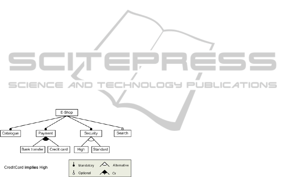
feature diagram notation used in this article is ex-
plained in Figure 1. The E-Shop FM consists of a
”catalogue” mandatory feature, two possible payment
methods from which one or both could be selected, an
exclusive alternative of security levels and an optional
search feature. FM constraints can be defined, in this
case ”credit card” implies a high level of security.
Figure 1: Feature Model from an E-shop. Source: Wikime-
dia commons.
Features composing a FM depict different parts of
a system without any clear separation. For instance
the wiper FM (B
¨
uhne et al., 2004) depicts both the
physical variability of a car wiper and the features of-
fered to the car drivers. The absence of feature types
makes these models popular as there are no limits for
the expression of design artifacts. But at the same
time, (B
¨
uhne et al., 2004) have demonstrated that de-
picting information in a single FM leads to feature re-
dundancies due to the tree structure. As a result, sepa-
ration of variability concerns into multiple FM seems
to be crucial for understanding (Mannion et al., 2009)
and manipulating (Acher et al., 2012) the many dif-
ferent faces of variability. Each of these FM focuses
on a viewpoint on variability which makes easier to
handle variability for each stakeholder.
2.2 SPL Configuration
The configuration process is an important task of SPL
management: producing a particular product variant
based on a selection of features to fit the customers’
needs. In this context, a configuration is a specific
combination of FM features such as hierarchical de-
composition, operators (Or, optional, etc.) and con-
straints of FM.
As stated by (White et al., 2009), when designers
and developers configure a system according to re-
quirements, the enforcement of FM constraints can
limit them in their design choices. Moreover, the
separation of the variability in multiple FMs is also
a source of complexity due to many dependencies
across FMs. The fusion of all FMs into one for con-
figuration purposes seems to solve this issue but re-
sults in a large FM that mixes different facets: this
may lead to invalid configurations and thus ineffi-
cient products. Some solutions exist to overcome
these problems. (Rosenm
¨
uller and Siegmund, 2010)
propose an implementation of a configuration com-
position system defining a step-by step configura-
tion (Czarnecki et al., 2005b) using partial configura-
tions (Benavides et al., 2010). Thus, some portion of
FM can be configured independently, without consid-
ering all the constraints (coming from the other con-
figuration) at configuration time. Then, constraints
amongst configurations may be solved by implement-
ing consistency transformations such as in (Acher
et al., 2009).
2.3 Model-driven User Interfaces
Variability
Model-Driven UI calls for specific models and ab-
straction. These models address the flow of user inter-
faces, the domain elements manipulated during the in-
teraction, the models of expected UI quality, the lay-
out, the graphical rendering, etc. In addition, each
model corresponds to a standard level of abstraction
as identified in the CAMELEON Reference Frame-
work (CRF) (Calvary et al., 2003). The CRF aims at
providing a unified view on modelling and adaptation
of UI. In the CRF, each level of abstraction is a po-
tential source of variability. Modifying a model of a
specific level of abstraction corresponds to a specific
adaptation of the UI.
For instance in the CRF, the most abstract model,
the task model, depicts the interaction between the
user and the features offered by the software. Adding
or removing a task results in modifying the software
features. Considering this, we can assume that there is
a direct link between classical feature modelling and
VariabilityManagementSupporting
theModel-drivenDesignofUserInterfaces
547
task modelling such as presented in by (Pleuss et al.,
2012). In this work, a task model is derived from an
initial FM. However the authors don’t go any further
in describing the variability related to interaction and
UI (graphical components, behavior, etc.).
(Gabillon et al., 2013) present an integrated vision
of functional and interaction concerns into a single
FM. This approach is certainly going a step farther by
representing variability at the different HCI abstrac-
tion levels of CRF. However, this approach has sev-
eral drawbacks. On the one hand, this approach de-
rives functional variability only from the task model,
limiting the functional variability of the software. On
the other hand, all the UI variations are mixed into a
single all encompassing FM which blurs the various
aspects for comprehension and manipulation of vari-
ability (Mannion et al., 2009).
Finally, Martinez et al. (Martinez et al., 2009) pre-
sented an initial experience on the usage of multiple
FMs for web systems. This work showed the feasibil-
ity of using multiple FMs and the possibility to define
a process around it. It implements FMs for a web sys-
tem, HCI scenario, a user model (user impairments),
and a device. However, this approach does not con-
sider the variability of UI design related models.
A few works in SPL for UI have been published.
A large part is dedicated to the main variability depic-
tion (using FMs) but they do not directly address the
configuration management. Configuration is a parti-
cular issue when considering end-user related require-
ments which may be fuzzily defined.
3 UI-SPL APPROACH
Model-driven UI design is a multi-stakeholders
process (Garc
´
ıa Frey et al., 2014b) where each
model –representing a particular subdomain of UI
engineering– is manipulated by specific stakeholders.
For instance, the choice of graphical widgets to be
used (e.g. radio button, drop-down list, etc.) is done
by a graphical designer, sometimes in collaboration
with the usability expert and/or the client. Our model-
driven UI design approach (Garc
´
ıa Frey et al., 2014a)
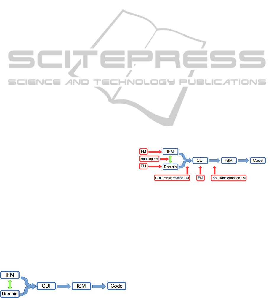
relies on a revised version of the CRF framework (fig-
ure 2). It consists of two base metamodels, the Do-
main metamodel -representing the domain elements
manipulated by the application as provided by clas-
Figure 2: Model-Driven UI design process.
sical domain analyst) and the interaction flow model
(IFM) (OMG, 2013). From these models we derive
the Concrete User Interface model (CUI) which de-
picts the application ”pages” and their content (i.e.,
widgets) as well as the navigation between pages. The
CUI metamodel aims at being independent of the final
implementation of any graphical elements. Finally,
the obtained CUI model is transformed into an Im-
plementation Specific Model (ISM) that takes into ac-
count platform details (here platform refers to UI tool-
kit such as HTML/JQuery, Android GUI, etc.). A last
model-to-text transformation generates the code ac-
cording to the ISM. This separation allows for sepa-
rate evolution of CUI metamodel and implementation
specific metamodel and code generation.
We propose a multiple feature models (multi-FM)
approach (see section 3.1) to describe the various
facets of UI variability (e.g., UI layout, graphical el-
ements, etc.). In a second time, (see section 3.2) we
introduce our specific view on configuration on this
multi-FM and its implementation in our model-driven
UI design approach (see section 3.3).
3.1 Multi-FM Approach
Classical FM approaches combine different func-
tional features (Pleuss et al., 2012). In the specific
context of UI design, we propose to rely on a similar
approach for managing variability of each UI design
concern. UI variability is thus decomposed into FMs
(figure 3).
Figure 3: Variability models (FM) coverage on our UI mod-
elling framework.
Each of these FMs is related either to a model, a
metamodel, a mapping or a transformation depending
on the nature of the information it conveys:
• Models: Three FMs in figure 3 manage variations
at the model level (IFM, Domain and CUI). For
example on the domain model, the FM can ex-
press alternative descriptions of a same concept.
• Mappings: The variability of the mapping be-
tween IFM and Domain can be managed by a
mapping FM. Indeed, UI states can involve dif-
ferent concepts in the domain model.
• Transformations: Variability can be expressed in
transformation FMs at the level of two transfor-
mations: (1) between IFM, Domain and CUI, (2)
MODELSWARD2015-3rdInternationalConferenceonModel-DrivenEngineeringandSoftwareDevelopment
548
between CUI and ISM. For example, a widget de-
scribed in CUI can be represented differently ac-
cording to the context in ISM.
By scoping the FM to a specific concern, our ap-
proach allows to focus only on the variations related
to the underlying concern. However, all the concerns
are interrelated in the generation process: the IFM,
Domain and CUI are in relation together (derivation
traceability, explicit mapping, etc.). Thus, the FMs
are interrelated as well following these relationships,
leading to dependencies between FMs. The FM re-
sponsible of transformation to CUI (i.e., elements to
be displayed) configuration is directly dependent to
the mapping between domain elements and IFM. For
instance, if the photo (Domain) is not mapped to a se-
lection state (IFM), the generated CUI list would not
contain this photo.
3.2 Configuration: The Specific Case of
Rapid Prototyping
End-user requirements are crucial in user centred de-
sign. They are often not formally defined: they can
be partial or provide not enough details to precisely
determine the UI design. Thus, UI designers have to
propose various product versions (prototypes) to end-
users. A common practice is to use rapid prototyping.
Rapid prototyping is a user-centred iterative process
where end-users give feedback on each produced pro-
totype. Prototype production should be rapid enough,
e.g. using automatic generation, to perform many as-
sessments in a limited amount of time. End-users will
thus elicit the way they prefer interacting with the
system, the best widgets and representations for their
tasks. In fact, through these iterations they elicit the
product configuration that best fits their needs.
Only a portion of the UI could be tested at each
iteration focusing on one particular UI aspect and
standing on a partial configuration (Benavides et al.,
2010). For instance, configuring content of a specific
page or a specific interaction state.
Some of the relations amongst FM (mainly the
constraints) can also be relaxed in this approach: we
provide more freedom to the designers through its
configurations. For instance, some types of list re-
quire to be filled by a picture/photo which may have
been removed by another configuration. Configura-
tion reconciliation may be a time consuming task,
which may delay the product elicitation. Indeed due
to the rapid prototyping requirement (i.e., getting a
end-user feedback on generated UI after a one or
two minutes configuration) we should relax the con-
straints.
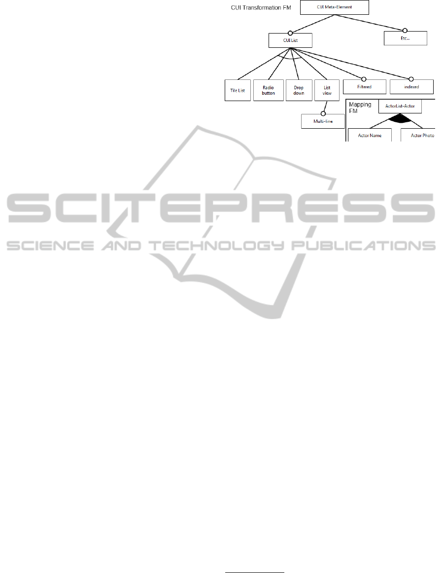
Figure 4: CUI Transformation FM Diagram excerpt for List
configuration.
In order to illustrate the process above, let’s intro-
duce a simple application example. The application
1
proposes to search actors that play in a film, whose
name is given by the user; then the user is able to se-
lect one actor to see more detailed information (birth
date, photos, etc.). This application consists of two
interaction flow states: one for searching by film and
displaying the list of actors and one for displaying in-
formation about the selected actor. In this example,
the UI designer may want to test the most appropri-
ated way to select the actor
2
. Thus the designer has
to propose several configurations for the selection of
the actor. The actor selection is supported by different
types of lists as depicted by the CUI metamodel (tile
list, radio-button, etc.) and the information that this
list should convey (actors photo, name, etc.).
The rapid prototyping configuration occurs on the
transformation between IFM, Domain and CUI Mod-
els (figure 3). This configuration stands on the combi-
nation of two FM. First, the “Mapping FM” (mapping
between IFM and domain) which depicts the configu-
ration of the information conveyed by the list (see fig-
ure 4 lower right frame Mapping FM). Secondly, the
“CUI transformation FM” that depicts the variability
of the widgets to be generated. Figure 4 shows only
the portion related to the list that is used in this FM.
The FM subsets of the figure correspond to a UI
designer specific viewpoint when she starts to con-
figure the actors selection. The designer will have to
choose configurations amongst the variability choices
expressed by the combination of those two FM in or-
der to produce several prototypes that could satisfy
end-users needs.
1
This example is supported by the Neo4J tutorial: Movie
DB, www.neo4j.com
2
We focus on a specific widget but other factors are to
be adjusted by the interface designer like style, layout, etc.
VariabilityManagementSupporting
theModel-drivenDesignofUserInterfaces
549
3.3 Configuring Transformations
The implementation of our approach relies on an ex-
isting system that derives a UI from a set of design
models (interaction flow and domain model) using
successive model transformations (Sottet and Vagner,
2014). This initial system was not taking into account
the variability configuration. We added the possibil-
ity of configuring the system using a specific UI dedi-
cated to specific configurations. Note that such UI can
also be generated from the FM models as in (Boucher
et al., 2012). In addition, as mentioned in section 3.2,
we should not freeze the generation/transformations
until everything has been configured, thus we rely on
partial variability configuration. As a result, we keep
our initial tool behavior: it should generate an exe-
cutable UI even if no explicit configuration is pro-
vided (i.e., using a default transformation heuristic).
We modified our initial tool by adding the configura-
tion as a parameter of the transformation that derive
a CUI from the interaction flow and domain models
with no impact on other transformations.
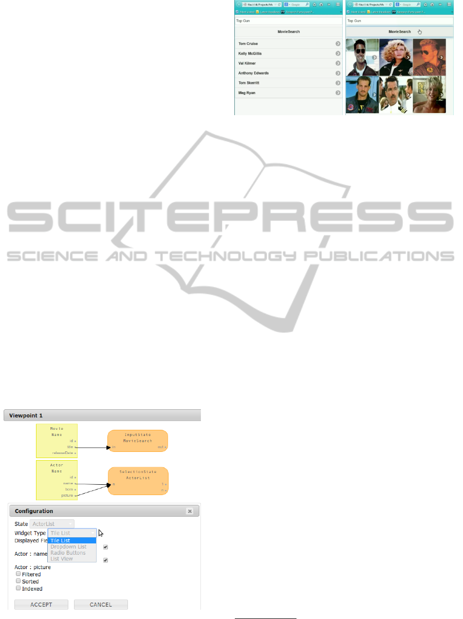
In order to perform a configuration, the designer
uses the interface provided in figure 5. She first se-
lects the input state model element (e.g., selection
state “ActorList”) the type of widget (e.g., among the
type of lists) using a scroll bar. In addition she can se-
lect/deselect the domain element manipulated by this
state (configuration of the mapping FM), for instance
removing/adding the Actor name and Actor picture
that could be displayed by the list.
Once the designer has finished the configuration
she can choose to launch the generation process. The
transformation chain will generate the configured UI
Figure 5: Upper part: excerpt of the application design
models (Domain and IFM). Lower part: configuration In-
terface for a given State (here “ActorList”).
Figure 6: At left: List View configuration for actor selection
displaying actor names, at right Tile List configuration with
actor images.
part within the rest of the application. End-users
are able to evaluate the configured part inside the
whole application interaction process. This task has
to be done for each of the identified configurations
that have to be tested. Figure 6 shows the result of
two UIs generated from two different list configura-
tions. A video summarizing the edition of models
and the realization of configurations, including the au-
tomatic generation of the prototypes, is available at
http://youtu.be/78t11o0jatU.
Once a convincing configuration is positively
evaluated by the end-users, it is stored to be used
for the final product. The final product configu-
ration should be done by composing all the rele-
vant configurations, using for instance the approach
by (Rosenm
¨
uller and Siegmund, 2010)
3
.
4 CONCLUSIONS AND
PERSPECTIVES
We have considered in this article the issue related to
UI variability due to its numerous facets (e.g., graph-
ical design, development, usability, etc.) and to the
diversity of its stakeholders profiles. Moreover, UI
design encounters the difficulty to align the products
with fuzzily defined user requirements. This com-
plexity can lead to an inefficient UI design process,
which has an impact on the UI design costs.
Therefore, we proposed an approach to manage
UI variability based on MDE and SPL, integrating
SPL management into our current MDE UI design
process. In this approach, all UI design stakeholders
can express the variability on the models, metamod-
els, mappings and transformations by defining multi-
ple FM related to each of these assets. The separation
of concerns is thus at the heart of this design process.
3
Configuration composition has not been implemented
in our tool yet.
MODELSWARD2015-3rdInternationalConferenceonModel-DrivenEngineeringandSoftwareDevelopment
550

However, in order to build a viable product, the stake-
holders have to reconcile their viewpoints when con-
figuring products. The proposed approach is based on
multi-step partial configurations. Default transforma-
tion heuristics are then used when no explicit config-
uration is given. These partial configurations can be
refined by all stakeholders including end-users.
More particularly, in the case of rapid prototyp-
ing, the UI designer has to configure the product and
test it on end users. She can focus on a specific point,
using partial configurations and test them with end-
users. We implemented this approach in our existing
UI model transformations where model transforma-
tions are parameterized by partial configurations and
rely on heuristics to generate default choices for the
features that are not configured.
We plan to work on the multiple FM dependency
management in the configuration process as proposed
by (Acher et al., 2009). This would guide the stake-
holders with the variability viewpoints (i.e, partial
configurations) reconciliation. We have to explore the
merging of partial configurations in order to produce
a global product configuration according to the global
constraints.
Finally, we discovered that the variability is man-
ifold and multi-dimensional in the design of UIs and
that FMs are of several types. We think that build-
ing a taxonomy of these different FM could help us in
understanding more precisely UI variability and could
lead us to the reuse of variability assets across projects
and domains.
ACKNOWLEDGEMENTS
This work has been supported by the FNR CORE
Project MoDEL C12/IS/3977071.
REFERENCES
Acher, M., Collet, P., Lahire, P., and France, R. B. (2012).
Separation of concerns in feature modeling: support
and applications. In Proc. of the 11th conf. on Aspect-
oriented Software Development.
Acher, M., Lahire, P., Moisan, S., and Rigault, J.-P. (2009).
Tackling high variability in video surveillance sys-
tems through a model transformation approach. In
MISE’09. ICSE Workshop, pages 44–49. IEEE.
Batory, D., Azanza, M., and Saraiva, J. (2008). The objects
and arrows of computational design. In Model Driven
Engineering Languages and Systems. Springer.
Benavides, D., Segura, S., and Ruiz-Cort
´
es, A. (2010). Au-
tomated analysis of feature models 20 years later: A
literature review. Information Systems, (6).
Boucher, Q., Perrouin, G., and Heymans, P. (2012). Deriv-
ing configuration interfaces from feature models: A
vision paper. VaMoS ’12, pages 37–44.
Brummermann, H., Keunecke, M., and Schmid, K. (2011).
Variability issues in the evolution of information sys-
tem ecosystems. In Proc. of the 5th Workshop on Vari-
ability Modeling of Software-Intensive Systems.
B
¨
uhne, S., Lauenroth, K., and Pohl, K. (2004). Why is it
not sufficient to model requirements variability with
feature models. In Workshop on Automotive Require-
ments Engineering (AURE’04), at RE’04, Japan.
Calvary, G., Coutaz, J., Thevenin, D., Limbourg, Q., Bouil-
lon, L., and Vanderdonckt, J. (2003). A unifying ref-
erence framework for multi-target user interfaces. In-
teracting with Computers, 15(3):289–308.
Clements, P. and Northrop, L. (2002). Software product
lines. Addison-Wesley Boston.
Czarnecki, K., Antkiewicz, M., Kim, C. H. P., Lau, S., and
Pietroszek, K. (2005a). Model-driven software prod-
uct lines. In Companion to the 20th annual ACM SIG-
PLAN conference on Object-oriented programming,
systems, languages, and applications. ACM.
Czarnecki, K., Helsen, S., and Eisenecker, U. (2005b).
Staged configuration through specialization and mul-
tilevel configuration of feature models. Software Pro-
cess: Improvement and Practice, 10(2):143–169.
DIS, I. (2009). 9241-210: 2010. ergonomics of human sys-
tem interaction-part 210: Human-centred design for
interactive systems. International Standardization Or-
ganization (ISO). Switzerland.
Gabillon, Y., Biri, N., and Otjacques, B. (2013). Designing
multi-context uis by software product line approach.
In ICHCI’13.
Garc
´
ıa Frey, A., Sottet, J.-S., and Vagner, A. (2014a).
Ame: An adaptive modelling environment as a col-
laborative modelling tool. In Proc. of the 2014 ACM
SIGCHI Symposium on Engineering Interactive Com-
puting Systems, EICS’14.
Garc
´
ıa Frey, A., Sottet, J.-S., and Vagner, A. (2014b). To-
wards a multi-stakehoder engineering approach with
adaptive modelling environments. In Proc. of the 2014
ACM SIGCHI Symposium on Engineering Interactive
Computing Systems, EICS’14.
Mannion, M., Savolainen, J., and Asikainen, T. (2009).
Viewpoint-oriented variability modeling. In COMP-
SAC’09.
Martinez, J., Lopez, C., Ulacia, E., and del Hierro, M.
(2009). Towards a model-driven product line for web
systems. In 5th Model-Driven Web Engineering Work-
shop MDWE 2009.
OMG (2013). IFML- interaction flow modeling language.
Pleuss, A., Hauptmann, B., Dhungana, D., and Botterweck,
G. (2012). User interface engineering for software
product lines: the dilemma between automation and
usability. In EICS, pages 25–34. ACM.
Pohl, K., B
¨
ockle, G., and Van Der Linden, F. (2005). Soft-
ware product line engineering: foundations, princi-
ples, and techniques. Springer.
VariabilityManagementSupporting
theModel-drivenDesignofUserInterfaces
551

Rosenm
¨
uller, M. and Siegmund, N. (2010). Automating
the configuration of multi software product lines. In
VaMoS, pages 123–130.
Sottet, J.-S. and Vagner, A. (2013). Genius: Generating us-
able user interfaces. arXiv preprint arXiv:1310.1758.
Sottet, J.-S. and Vagner, A. (2014). Defining domain spe-
cific transformations in human-computer interfaces
development. In 2nde Conf. on Model-Driven Engi-
neering for Software Developement.
White, J., Dougherty, B., Schmidt, D. C., and Benavides, D.
(2009). Automated reasoning for multi-step feature
model configuration problems. In Proc. of the 13th
Inter. Software Product Line Conference.
MODELSWARD2015-3rdInternationalConferenceonModel-DrivenEngineeringandSoftwareDevelopment
552
