
DPSK Signals Demodulation Based on a Graded-index Multimode
Fiber Mismatch Spliced between Two Single-mode Fibers
Xiaoyong Chen and Paloma R. Horche
Departamento de Tecnología Fotónica y Bioingeniería, Universidad Politécnica de Madrid,
Avda. Complutense 30, Madrid, Spain
Keywords: Optical Fiber Communication, Optical Receiver, Differential Phase Shift Keying, Multimode Fiber, Modal
Interference, Mach-Zehnder Interferometer.
Abstract: Differential phase shift keying (DPSK) signal has been shown as a robust solution for next-generation
optical transmission systems. One key device enabling such systems is the delay interferometer, converting
a phase signal into an intensity modulated signal to be detected by a photodiode. Usually, a Mach-Zehnder
interferometer (MZI) is used for DPSK signals demodulation. In this work, we develop an alternative all-
fiber MZI, which is based on a graded-index multimode fiber (MMF) mismatch spliced between two single-
mode fibers. Interferometer performance is analyzed through both theory and experiment. Experimental
results of transmission spectrums show that interference extinction ratio as high as 18 dB is obtained.
Finally, we demonstrate, through simulation, that our proposed all-fiber MZI can be used for DPSK signals
demodulation. Receiver sensitivity of -22.5 dBm at a bit error rate of 10
-15
is obtained in the simulation for
detecting a 40 Gbps DPSK signal, which is 1.3±0.2 dB penalty compared to the conventional receiver.
1 INTRODUCTION
Differential Phase Shift Keying (DPSK) signal,
which encodes the binary data as either a 0 or π
optical phase shift between the adjacent bits, has
been proposed for using in optical transmission
systems, since it exhibits superior optical signal to
noise ratio (OSNR) sensitivity, high tolerance to
chromatic dispersion and high robustness to fiber
nonlinear effects (Gnauck and Winzer, 2005; Winzer
and Essiambre, 2006). Compared with the on-off
keying (OOK), the most obvious benefit of DPSK is
the ~ 3-dB OSNR improvement to reach a given
BER. Such advantage can be used to extend the
transmission distance, reduce optical requirements,
and relax component specifications. Note, however,
that this ~ 3-dB benefit can only be obtained using
balanced detection.
Usually, a conventional Mach-Zehnder
interferometer (MZI) is used as the delay
interferometer (DI) for DPSK signals demodulation,
due to the simple structure and easy implementation.
However, the conventional MZIs have one obvious
drawback: the performance is easily affected by the
environment, such as temperature, since two beams
go through two different physical paths.
In order to improve the MZI performance, all-
fiber MZI, which is based on a multimode fiber
(MMF) located between two single-mode fibers
(SMFs), is proposed to take place of the
conventional MZI in recent years. Nowadays, all-
fiber MZIs have been studied and developed to act
as novel optical devices, e.g., a temperature sensor, a
strain sensor, a refractive index sensor, a fiber lens, a
bandpass filter, and a signal demodulator
(Mohammed, Mehta and Johnson, 2004; Lize,
Gomma and Kashyap, 2006; Tripathi et al., 2009;
Tripathi et al., 2010; Wang at al., 2011; Xue and
Yang, 2012; Hofmann et al., 2012; Shao et al.,
2014). The principle of all-fiber MMF based MZIs is
that, the optical power is coupled into two
dominated modes, LP
01
and LP
02
, excited in the
MMF, when light transmits from the input-SMF to
the MMF; then, these two modes propagate along
the MMF with different propagation constants, and
interfere with each other when they transmit from
the MMF to the output-SMF. Although some high-
order modes are also excited and propagating in the
MMF, they will not seriously affect the interference
occurs between modes LP
01
and LP
02
. Therefore,
such structure, SMF-MMF-SMF (SMS), can
approximately work as a MZI. The main advantage
of all-fiber MMF based MZI, compared to the
conventional MZI, is low-cost, easy manufacture,
13
Chen X. and R. Horche P..
DPSK Signals Demodulation Based on a Graded-index Multimode Fiber Mismatch Spliced between Two Single-mode Fibers.
DOI: 10.5220/0005332500130019
In Proceedings of the 3rd International Conference on Photonics, Optics and Laser Technology (PHOTOPTICS-2015), pages 13-19
ISBN: 978-989-758-092-5
Copyright
c
2015 SCITEPRESS (Science and Technology Publications, Lda.)
and performance improvement due to the two arms
sharing the same hardware. However, the drawback
of such MZIs is also obvious: the interference
extinction ratio (ER) is very low, since the power
coupled into mode LP
01
is much higher than that
coupled into the mode LP
02
. In addition, the other
high-order modes exited and propagating in the
MMF will also affect the interference ER.
To improve the interference ER, some schemes,
through using a special fiber to replace the
commercial graded-index MMF in the SMS
structure, have been proposed, including: a photonic
crystal fiber (PCF) (Du et al., 2010), a double
cladding fiber (Pang et al., 2009), a thin-core fiber
(Zhu et al., 2010), and a graded-index MMF with a
central dip (Chen, Horche and Minguez, 2014). In
this work, we propose an alternative all-fiber MZI,
which is a graded-index MMF mismatch spliced
between two SMFs, as shown in Figure 1(a). With a
transverse offset, more power is coupled into the
first non-circular symmetrical mode LP
11
, while less
power is coupled into fundamental mode LP
01
,
resulting in balancing the power difference between
two beating modes, and thus improving the
interference ER. This improvement makes it
possible to use for DPSK signals demodulation.
Some previous papers have studied the
application of an all-fiber in-line MZI using as a
DPSK demodulator, which includes a birefringent
fiber based MZI (Chow and Tsang, 2005), a special
step-index MMF based MZI (Lize, Gomma and
Kashyap, 2006), a PCF based MZI (Du et al., 2010),
and an all-fiber MZI based on a graded-index MMF
with a central dip in index profile (Chen, Horche and
Minguez, 2014). In this work, we propose an
alternative DPSK receiver, which is based on our
proposed all-fiber MZI. In comparison with the
schemes mentioned above, our proposed DPSK
receiver also shows merits of low-cost, easy
manufacture and good performance.
The paper is organized as follows. The theory of
the proposed all-fiber MZI is presented in Section 2.
Experimental setup and results are presented and
discussed in Section 3. DPSK receiver based on the
proposed all-fiber MZI for 40 Gbps DPSK signals
demodulation is presented, and simulation results are
commented in Section 4. Finally, conclusions are
drawn in Section 5.
2 THEORY
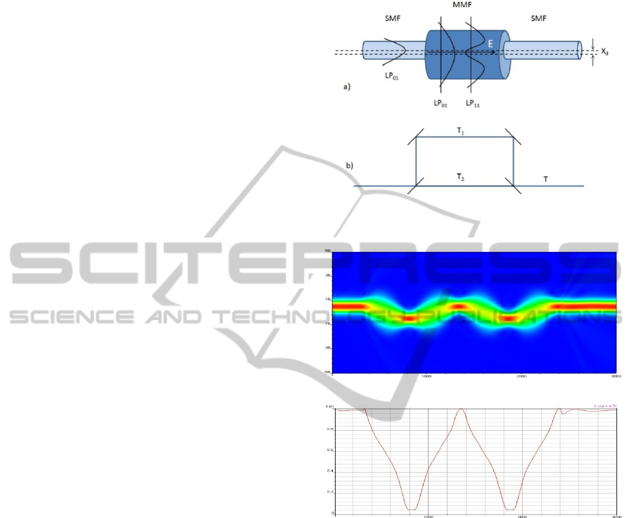
Figure 1(a) shows our proposed all-fiber MZI, which
is based on a graded-index MMF mismatch spliced
between two SMFs. Note that only the core fibers
are drawn in this figure.
Figure 1: Principle of the proposed MZI (a) compared
with the conventional MZI (b).
(a)
(b)
Figure 2: (a) Power distribution inside the graded-index
MMF in the case of incident light offset from the MMF
center (+5 µm); (b) Power distribution along the optical
axis of +5 µm.
According to the theory of modal interference,
which is a well-known phenomenon and it had been
studied by many authors (Horche, Muriel and Pereda,
1989; Abe et al., 1992; Blahut and Kasprzak, 2004;
Mohammed, Mehta and Johnson, 2004; Tripathi et
al., 2009; Tripathi et al., 2010; Wang at al., 2011;
Xue and Yang, 2012; Hof mann et al., 2012; Shao et
al., 2014), the excited modes in the MMF interfere
with each other along the propagation direction, and
the power distribution along the propagation
direction can be drawn as Figure 2(a). It can be seen
that the power distributes periodically along the
MMF, and almost all the power is coupled back to
the output-SMF. Figure 2(b) shows the
PHOTOPTICS2015-InternationalConferenceonPhotonics,OpticsandLaserTechnology
14

corresponding power distribution along the
propagation axis (+ 5µm). Defining the field
distribution of each excited mode LP
nk
as
, and
assuming that the transverse offset between the
input-SMF and the MMF is x
d
. Also, assuming that
the output-SMF has the same parameters as the
input-SMF and has the same transverse offset x
d
, the
power coupled into the output-SMF can be written
as (Kumar et al., 2003):
P
=
,
∗
=
exp
1
where E
in
is the normalized input field and
,
are the normalized eigenmode at the end of the
MMF.
and
are, respectively, the coupling
coefficient and propagation constant of each excited
mode in the MMF. The equation indicates that the
power coupled into the output-SMF depends on the
relative phase difference at the end of the MMF (L).
Although many modes are excited and
propagating in the MMF, most of the power is
coupled into modes LP
01
and LP
11
, due to the
transverse offset between the input-SMF and the
MMF. Therefore, our scheme can approximately
work as a MZI. Also, since the power difference
between these two modes is reduced much,
compared to the SMS structure where the MMF is
aligned to the SMFs, interference ER of our
proposed MZI is improved. In addition, compared
with the conventional MZI built with two fiber
couplers, as shown in Figure 1(b), our proposed all-
fiber MZI performs more stably, because both arms
share the same hardware, resulting in less sensitive
to the external environment, such as temperature. It
should be noted that in the conventional MZI, the
light is first split equally into two beams by a fiber
coupler, and then they pass through two different
physical paths. Finally, they re-combine together by
another fiber coupler and interfere with each other
due to the phase difference between two beams.
Despite a little power is coupled into some high-
order modes, these modes do not seriously affect the
transmission spectrum of our proposed all-fiber MZI.
The only influence they generate is slightly changing
the interference ER, leading to the outline of
transmission spectrum periodically oscillating with
the wavelength (or frequency), which is verified in
Section 3. If we ignore the high-order modes excited
in the MMF, the transmission function (Equation (1))
of our proposed all-fiber MZI can be simply
expressed as that of a conventional MZI:
=
2
cos (2)
where T
1
and T
2
represent the intensity of modes
LP
01
and LP
11
, respectively. φ is the phase difference
between these two modes, and it can be written as:
=∆
=∆
3
where L is the MMF length, ∆ is the propagation
constants difference between modes LP
01
and LP
11
.
In combination with (2) and (3), we can see that the
power coupled into the output-SMF is only decided
by the MMF length, L.
To concentrate the power on the axis location of
the output-SMF at the end of the MMF, the phase
difference between these two dominated modes
should be equal to an integer multiple of 2π. In other
words, the MMF length should be an integer
multiple of beat length z
, which can be written as:
=
2
|
|
4
where
and
are the propagation constants of
modes LP
01
and LP
11
, respectively.
The transmission spacing ∆λ between the
adjacent constructive peaks (or destructive valleys)
can be written as:
∆=
|
|
=
2
|
|
=
5
where n
01
and n
11
are the effective index of modes
LP
01
and LP
11
,
,
respectively. We can see that,
according to (5), the spacing ∆λ is inversely
proportional to MMF length. In addition, the
propagation constants difference between the two
beating modes can be approximately written as
(Horche et al., 1989):
=
λ
4
6
with
U
01
=2.405e
-1/
V
forthemode
L
P
0
1
U
11
=3.83e
-1/
V
forthemode
L
P
1
1
=
2
where a is the core radius, λ is the wavelength in
vacuum,
is the maximum refractive index of
the core and
is the cladding refractive index.
Combining with the (5), the time delay between
two beating modes can be defined as:
∆=
/
/
=
∆
=
∆
(7)
DPSKSignalsDemodulationBasedonaGraded-indexMultimodeFiberMismatchSplicedbetweenTwoSingle-mode
Fibers
15

It shows that the delay time only depends on the
effective index difference ∆ and the MMF length,
L. In order to evaluate the delay efficiency of our
proposed all-fiber MZI, we also define another
parameter called delay coefficient, ∆ ,
corresponding to the time delay in a one-meter
MMF:
∆=
∆
=
∆
=
∆
(8)
We can that the delay coefficient only depends
on the effective index difference ∆, which is
determined by the MMF refractive index profile.
3 EXPERIMENT
According to the theoretical analysis in Section 2,
we built an experimental setup, as shown in Fig. 3,
for observing the transmission spectrum of our
proposed all-fiber MZI. A white source with almost
a flat spectrum in the range from 1 µm to 1.62 µm
was used as the light source. The SMFs (9 µm /125
µm) were the commercial standard SMFs compliant
with ITU-T G.652, and the MMF (50 µm /125 µm)
was also a commercial graded-index MMF, with
maximum core refractive index of 1.473 and
cladding refractive index of 1.4567. In the
experiment, the MMF was spliced between two
SMFs by two micro-positioners, for accurately
adjusting the transverse offset. Note that the micro-
positioners are not shown in Figure 3. Finally, the
output-SMF was directly connected to an optical
spectrum analyzer (OSA) for observing and
recording the transmission spectrum.
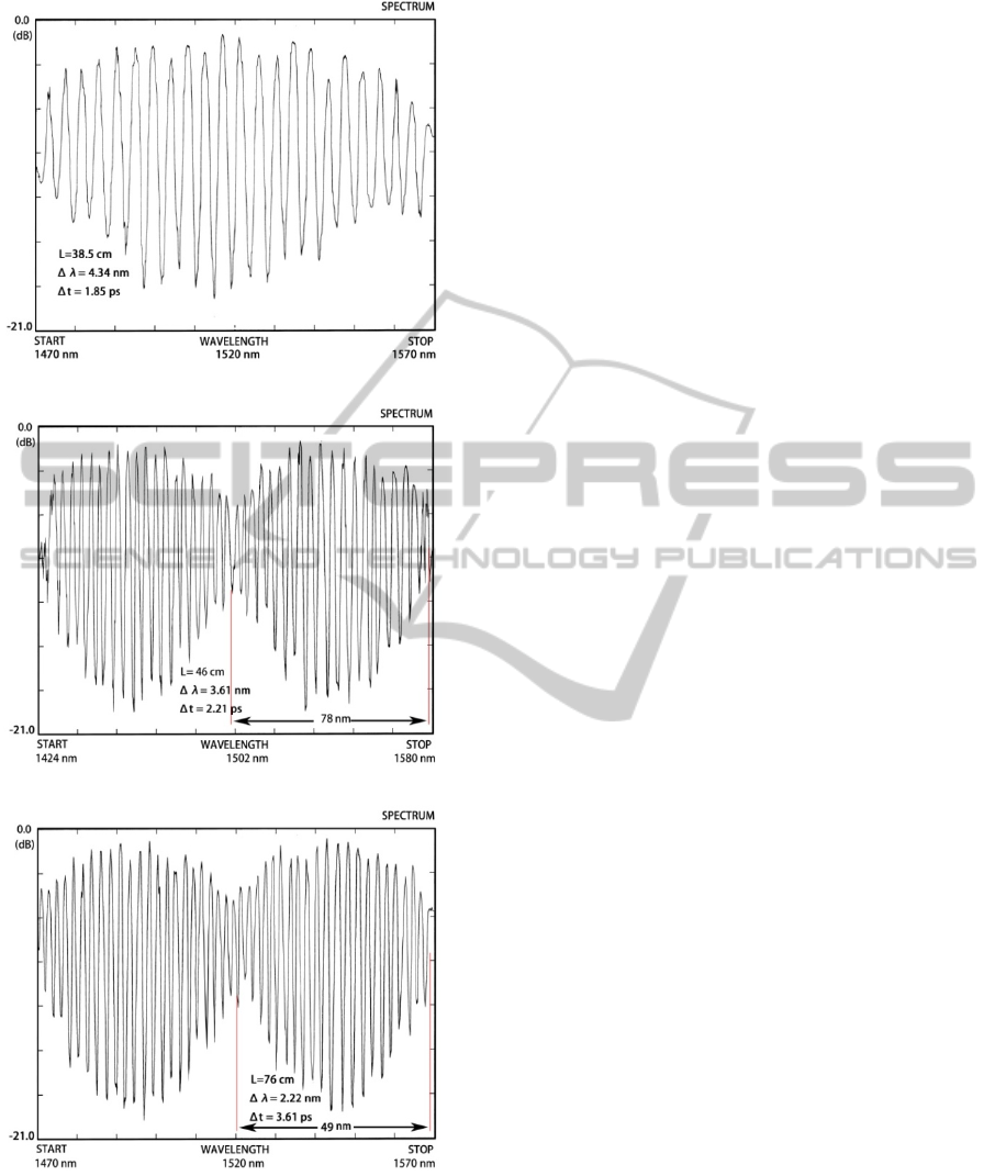
The experimental results of transmission
spectrums are shown in Figure 4, with different
MMF lengths of 38.5, 46 and 76 cm. As can be seen,
interference ER as high as 18 dB is obtained in the
experiment. These results agree with the theory
presented in Section 2: most power is coupled into
modes LP
01
and LP
11
, and power difference between
these two modes is small. Also, comparison between
Figure 4 (a) and (c) indicates that the transmission
spacing Δλ is inversely proportional to the MMF
length: increasing MMF length from 38.5 to 76 cm
results in a decrease of wavelength spacing Δλ from
4.34 to 2.22 nm.
Figure 4(a) also shows that a relative time delay
Δt of 1.85 ps, which is got through (7), is obtained
when the MMF length is 38.5 cm. According to (8),
it can be calculated that the delay coefficient Δd is
4.81 ps/m. This value is larger than that of step-
index MMF based MZI (Lize, Gomma and Kashyap,
2006) and birefringent fiber based loop mirror
(Chow and Tsang, 2005), which possesses delay
coefficients of 3.48 and 0.91 ps/m, respectively. It
implies that the required MMF length for generating
a certain time delay is much shorter. However, the
delay coefficient of our proposed all-fiber MZI
device is much smaller than that of all-fiber MZIs
proposed by Chen (Chen, Horche and Minguez,
2014) and Du (Du et al., 2010), which possesses
delay coefficients of 8.7 and 30.4 ps/m, respectively.
The transmission spectrums in Figures 4(b) and
(c) reveal the periodic nature on the change of the
interference ER. This phenomenon agrees with the
theoretical analysis mentioned in Section 2: some
high-order modes, such as modes LP
02
and LP
21
, are
excited and propagating in the MMF. Note,
however, that the transmission spectrum is mainly
determined by the phase difference between modes
LP
01
and LP
11
at the end of MMF. At a certain
wavelength, the output power reaches the minimum
due to the destructive interference, when the phase
Figure 3: Experimental setup. LED: light emitting diodes; MMF: multimode fiber; SMF: single-mode fiber; OSA: optical
spectrum analyzer.
PHOTOPTICS2015-InternationalConferenceonPhotonics,OpticsandLaserTechnology
16
(a)
(b)
(c)
Figure 4: Transmission spectrum of the all-fiber MZI
device with different MMF lengths of 38.5 cm (a), 46 cm
(b), and 76 cm (c).
difference is equal to even times of π. In theory, the
spectral period should be inversely proportional to
MMF length, which agrees with the experimental
results: increasing MMF length from 46 cm to 76 cm
leads to a decrease of spectral period from 78 nm to
49 nm.
4 PROPOSED MZI FOR DPSK
SIGNALS DEMODULATION
As mentioned in Section 1, interference ER is a very
important parameter for demodulating DPSK
signals, when an all-fiber MZI is used as a DPSK
demodulator. The high interference ER obtained in
the experiment make our proposed all-fiber MZI
device possible for using as a DPSK demodulator. In
this section, we verify, through simulation, that our
proposed all-fiber MZI can be used for DPSK
signals demodulation.
The MMF model used in the simulation is almost
the same as the graded-index MMF used in the
experiment. It can be theoretically calculated that the
delay coefficient is 4.93 ps/m, which is very close to
the results obtained in the experiment. The required
MMF length, thus, is 5.068m for demodulating a
40Gbps DPSK signal. Figure 5 shows the
transmission spectrum of the proposed all-fiber MZI
with MMF length of 5.068 m. It can be seen that
high interference ER is obtained in the simulation.
Simulation design of a back-to-back 40 Gbps
DPSK system, including a conventional transmitter
and a receiver based on our proposed all-fiber MZI,
is depicted in Figure 6. A the transmitter, a 1550 nm
continuous-wave source was modulated by a
LiNbO
3
Mzch-Zehnder modulator (MZM), driven
by a 40 Gbps precoded data stream, which is a
pseudo randam bit sequence of length 2
15
-1, to
generate a 40 Gbps DPSK signal. At the receiver,
the signal was first amplified by an erbium-doped
fiber amplifier (EDFA), and then the noise-loaded
signal was filtered by a bandpass filter with an 85-
GHz 3-dB bandwidth. After that, the signal was
demodulated by our proposed all-fiber MZI,
followed by a photodetector. Finally, a bit error rate
(BER) analyzer was used to analyze the quality of
the received signal. Note that the simulations were
carried out through OptiSystem.
The simulation results of back-to-back sensitivity
are shown in Figure 7. The sensitivity of our
proposed receiver is about -22.5 dBm at a BER of
10-15 and about -23.9 dBm at a BER of 10-9.
Compared with the conventional delay
interferometer based DPSK receiver built with two
fiber couplers (Gnauck and Winzer, 2005), our
proposed receiver has 1.3 ± 0.2 dB sensitivity
DPSKSignalsDemodulationBasedonaGraded-indexMultimodeFiberMismatchSplicedbetweenTwoSingle-mode
Fibers
17
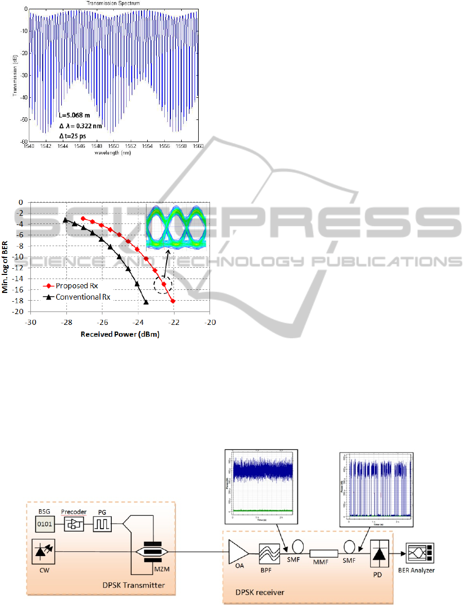
Figure 5: Transmission spectrum of the proposed all-fiber
MZI with MMF length of 5.068m.
Figure 7: BER as a function of received power.
penalty. This penalty is mainly caused by the
imbalanced detection, since the output-SMF only
provides one output port. This problem can be
solved by splicing a dual-core fiber at the output end
of the proposed MZI, thus, detecting the
demodulated signals in the two cores. However, it
should be noted this design is at the expense of
increasing the complexity of the receiver. In
addition, the MMF induced signal impairment can
also lead to sensitivity penalty. The relatively open
intensity eye shown in the inset demonstrates that
the proposed receiver can provide error-free
operation.
5 CONCLUSIONS
We have demonstrated, through theory and
experiment, an all-fiber MZI device, which is based
on a commercial graded-index MMF mismatch
spliced between two SMFs. In this structure, most of
the input power is coupled into modes LP
01
and LP
11
excited in the MMF. These two modes interfere with
each other along the propagation direction, and the
light power coupled into the output-SMF only
depends on the relative phase difference at the end
of the MMF. Thus, interference pattern can be
obtained at the exit of the output-SMF. Interference
ER, as high as 18 dB, is obtained in the experiment,
and a delay coefficient of 4.81ps/m is obtained also.
Finally, simulations of using the proposed all-fiber
MZI to demodulate a 40 Gbps DPSK signal are done.
Simulation results show that the proposed DPSK
receiver has similar performance as the conventional
receiver built with two couplers, but with 1.3 ± 0.2
dB sensitivity penalty.
Since the design of our proposed all-fiber MZI is
low-cost and easy manufactured, it will be used
widely in many optical applications in the future,
such as filters or temperature sensors. Moreover,
with the proper design, it can also be used as WDM
multiplexer and demultiplexer.
Figure 6: Simulation setup. CW: continuous wave; BSG: bit sequence generator; PG: pattern generator; MZM: Mach-
Zehnder modulator; OA: optical amplifier; BPF: bandpass filter; BER: bit error rate; PD: photodetector.
PHOTOPTICS2015-InternationalConferenceonPhotonics,OpticsandLaserTechnology
18

ACKNOWLEDGEMENTS
The authors would like to acknowledge support from
the China Scholarship Council (CSC). The authors
would also like to dedicate this work to the memory
of the recently deceased Professor Alfredo Martín
Mínguez.
REFERENCES
Abe, K., Lacroix, Y., Bonnell, L., Jakubczyk, Z., 1992.
Modal interference in a short fiber section: fiber length,
splice loss, cutoff, and wavelength dependences.
Journal of Lightwave Technology. vol. 10, no. 4, pp.
401-406.
Blahut, M., Kasprzak, D., 2004. Multimode interference
structures – properties and applications. Optica
Applicata. vol. XXXIV, no.4, pp. 573-587.
Chen, X., Horche, P.R., Minguez, A.M., 2014. DPSK
Signals Demodulation Based on a Multimode Fiber
with a Central Dip. In NOC 2014, Milan, Italy.
Chow, C.W., Tsang, H.K., 2005. Polarization-independent
DPSK demodulation using a birefringent fiber loop.
IEEE Photonics Technology Letters. vol. 17, no. 6, pp.
1313–1315.
Du, J., Dai, Y., Lei, G.K.P., Tong, W., Shu, C., 2010.
Photonic crystal fiber based Mach-Zehnder
interferometer for DPSK signal demodulation. Optics
Express. vol. 18, no. 8, pp. 7917-7922.
Gnauck, A.H., Winzer, P.J., 2005. Optical phase-shift-
keyed transmission. Journal of Lightwave Technology.
vol. 23, no. 1, pp. 115-130.
Hofmann, P., Mafi, A., Jollivet, C., Tiess, T.,
Peyghambarian, N., Schülzgen, A., 2012. Detailed
investigation of mode-field adapters utilizing
multimode-interference in graded index fibers. Journal
of Lightwave Technology. vol. 30, no. 14, pp. 2289-
2298.
Horche, P.R., López-Amo, M., Muriel, M.A., Martin-
Pereda, J.A., 1989. Spectral behavior of a low-cost all-
fiber component based on untapered multifiber unions.
IEEE Photonics Technology Letters. vol. 1, no. 7, pp.
184-187.
Horche, P.R., Muriel, M.A., Martin-pereda, J.A., 1989.
Measurement of transmitted power in untapered
multifibre unions: oscillatory spectral behaviour.
Electronics Letters. vol. 25, no. 13, pp. 843-844.
Kumar, A., Varshney, R.K., Antony, S., Sharma, P., 2003.
Transmission characteristics of SMS fiber optic sensor
structures. Optics Communications. vol. 219, no. 1-6,
pp. 215-219.
Lize, Y.K., Gomma, R., Kashyap, R., 2006. Low-cost
multimode fiber Mach-Zehnder interferometer for
differential phase demodulation. In SPIE 2006, San
Diego, USA.
Mohammed, W.S., Mehta, A., Johnson, E.G., 2004.
Wavelength tunable fiber lens based on multimode
interference. Journal of Lightwave Technology. vol. 22,
no. 2, pp. 469-477.
Pang, F., Liang, W., Xiang, W., Chen, N., Zeng, X.,
Chen, Z., and Wang, T., 2009, Temperature-
Insensitivity Bending Sensor Based on Cladding-
Mode Resonance of Special Optical Fiber, IEEE
Photonics Technology Letters, vol. 21, no. 2, pp. 76-
78.
Shao, M., Qiao, X., Fu, H., Li, H., Jia, Z., Zhou, H., 2014.
Refractive index sensing of SMS fiber structure based
Mach–Zehnder interferometer. IEEE Photonics
Technology Letters. vol. 26, no. 5, pp. 437-439.
Tripathi, S.M., Kumar, A., Marin, E., Meunier, J.-P., 2010.
Single-multi-single mode structure based band
pass/stop fiber optic filter with tunable bandwidth.
Journal of Lightwave Technology. vol. 26, no. 24, pp.
3535-3541.
Tripathi, S.M., Kumar, A., Varshney, R.K., Kumar, Y.B.P.,
Marin, E., Meunier, J.-P., 2009. Strain and
temperature sensing characteristics of single-mode-
multimode-single-mode structures. Journal of
Lightwave Technology. vol. 27, no. 13, pp. 2348-2355.
Wang, P., Brambilla, G., Ding, M., Semenova, Y., Wu, Q.,
Farrell, G., 2011. Investigation of single-mode–
multimode–single-mode and single-mode–tapered-
multimode–single-mode fiber structures and their
application for refractive index sensing. J. Opt. Soc.
Am. B. vol. 28, no. 5, pp. 1180-1186.
Wang, Q., Farrell, G., and Yan, W., 2008. Investigation on
single-mode–multimode–single-mode fiber structure.
Journal of Lightwave Technology. vol. 26, no. 5, pp.
512-519.
Winzer, P.J., Essiambre, R.-J., 2006. Advanced optical
modulation formats. Proceedings of the IEEE. vol. 95,
no. 5, pp. 952-985.
Xue, L.-L., Yang, L., 2012. Sensitivity enhancement of RI
sensor based on SMS fiber structure with high
refractive index overlay. Journal of Lightwave
Technology. vol. 30, no. 10, pp. 1463-1469.
Zhu, J.-J., Zhang, A.P., Xia, T.-H., He, S., and Xue, W.,
2010. Fiber-Optic High-Temperature Sensor Based on
Thin-Core Fiber Modal Interferometer, IEEE Sensors
Journal, vol. 10, no. 9, pp. 1415-1418.
DPSKSignalsDemodulationBasedonaGraded-indexMultimodeFiberMismatchSplicedbetweenTwoSingle-mode
Fibers
19
