
A Novel Multiband Filter Design based on Ring
Resonators and DSP Approach
M. R. Mokhtari, G. Rostami, M. Dolatyari and A. Rostami
OIC Research Group, School of Engineering-Emerging Technologies, University of Tabriz, Tabriz 5166614761, Iran
Keywords: Discrete-time Signal Processing, Multiband Filters, Optical Waveguide Filters, Pole-Zero Diagram, Ring
Resonators.
Abstract: This paper proposes a novel ring resonator based optical filter that has an outstanding multi narrow band
response due to adopting quasi structures such as Thue-Morse sequence as the radius-pattern. This capability
introduces this design approach as an effective method for the design of filters for emerging dense wavelength
division multiplexing networks. The design process incorporates analysing through the transfer matrix method
and the powerful discrete-time signal processing techniques. Giving an adequate overview of analysing basic
optical building blocks in the Z-domain, the procedure develops to analysing any optical structure imposed
by mathematical sequences. The proposal is discussed employing pole-zero diagrams, discrete-time signal
processing approach including apodization techniques. The point of the discrete-time signal processing
approach is that the effect of dominant optical parameters over operation is clarified through the pole-zero
position. Features like number of poles, bandwidth, and position of stop-bands can be controlled using ring
diameter ratio. Finally, apodization of coupling coefficients attains a filter with an FWHM of 0.3 nm.
1 INTRODUCTION
In recent years, with increasing the number of
channels, devising novel multi narrow band filters is
essential to enhance the current Dense Wavelength
Division Multiplexing (DWDM) networks.
Realization of such precise wavelength selective
filters plays a key role in improving the capacity of
optical networks and satisfying growing demand for
efficient photonic components. Furthermore, these
optical filters are capable of carrying out the role of
various photonic components such as add-drop
multiplexers, gain equalizers, dispersion
compensators, and interleavers. One of the widely
used structures for such optical components is the
micro ring-resonator. This research has focused on
ring-resonator based narrowband optical filter design
as a preferred method to separate single or multi
channels simultaneously and hence exploiting the full
bandwidth potential offered by optical fiber.
Important features of such a filter include narrow
bandwidth, ease of integration, and high side lobe
suppression. The realization of narrowband optical
filters such as Quasi-periodic structures is feasible by
utilizing two methods, multilayer structures and
micro ring-resonators. The optical properties of
Fibonacci class, ring-resonator and multilayer
structures studied respectively in (Rostami et al.,
2005) and (Rostami et al., 2004). Multi band filter
design is also possible by means of aperiodic Thue-
Morse class structures (Liu, 1997).
Dong et al. proposed a GHz-bandwidth optical
filter based on second-order and fifth-order ring
resonators. They have also used metal heaters situated
on top of the ring to tune the wavelength of filtering.
The filter demonstrates a 3 dB bandwidth f
3dB
=1.0
GHz and 1.9 GHz for 2
nd
- and 5
th
-order rings,
respectively (Dong, 2010).Park et al. demonstrated
3rd order micro ring-resonator filters, 100 GHz-
spaced 16 channels and 50 GHz-spaced 32 channels.
The radius of micro ring-resonators are 9 µm (Park,
2011). Since micro ring-resonators are capable of
performing as the basic building block for the design
of various optical components, we intend to hire this
potential for optical filter design. However, it is
possible to design 10 GHz filters using micro ring-
resonators but our design target is the standard of 0.3
µm for the bandwidth.
For the first time, this paper presents a unique
technique for the design of ring-resonator based
multiband filters with Thue-Morse class structures.
Applying Thue-Morse sequence over the radius of
101
R. Mokhtari M., Rostami G., Dolatyari M. and Rostami A..
A Novel Multiband Filter Design based on Ring Resonators and DSP Approach.
DOI: 10.5220/0005335401010107
In Proceedings of the 3rd International Conference on Photonics, Optics and Laser Technology (PHOTOPTICS-2015), pages 101-107
ISBN: 978-989-758-093-2
Copyright
c
2015 SCITEPRESS (Science and Technology Publications, Lda.)

Figure 1: One dimensional micro-ring resonator chains. (a)
Single channel SCISSOR chain whose system response
implement multiple poles, (b) Double channel SCISSOR
with separate resonances.
ring-resonators results in exceptional features such as
narrow stop-bands. The structure comprises two
distinct types of ring-resonators with different
radiuses because of the Thue-Morse pattern from
which the structure is constructed of. In
manufacturing point of view different radiuses is
simple to implement. It seems that using Quasi-
Periodic structures give the potential of an
exceptional design. We want to evaluate the
performance of such structures as a filter. In this
design, the difficult part is the design of a two-
dimensional structure with 16 rings, with a footprint
of 3.6 nm
2
, which is very small but it seems that has
no complexity.
The first step is to restrict the focus on two types
of micro ring-resonator based building blocks from
which the high-order coupled micro ring-resonator
chains can be constructed of. Optical building block
modelling in the Z-domain gives the opportunity of
applying Discrete-time Signal Processing (DSP)
techniques in the optical filter design process. Once
the transfer function in the Z-domain is available,
designer can observe whole the system characteristics
and complex parametrical dependencies of pole and
zero to other parameters in the pole-zero diagram.
During the design process, designer can vary optical
parameters and observe the pattern in which the pole
and zero moves. Varying device parameters
manipulates pole-zero positions (Kaalund et al.,
2004). Thus, adjusting pole-zero position is a possible
way of modifying spectral response in order to
optimize the performance of a filter. Designer can
make the stop/pass bands, narrow or wide by moving
pole-zero pairs toward/outward each other, sharpen
the edge roll-off of bands or even organise the value
of an optical parameter in different stages according
to a window function to optimize the output response,
which is a well-known technique in DSP and discrete
filter design. Pole-zero diagram illustrates the
stability and causality of a filter, which are the
essential characteristics of a system performing a
signal processing duty. All of these exploit DSP
approach that is a systematic approach to avoid
tedious electromagnetic methods and provides a
mathematical framework for easy description of
discrete-modelled optical filters and their
optimization. The purpose is the feasibility study of
exploiting design ideas related to signal processing
techniques like Z-transform and apodization. We
compare and contrast the characteristics of three
different Thue-Morse class structures in one and two
dimension.
The ratio of distinct ring-resonator radiuses and
the coupling coefficients are two key parameters that
control the number and the position of pole and zero
respectively. Various manipulating techniques can be
implemented over these parameters like apodization
to get the desired pole-zero locations and hence the
most efficient response.
Coupled ring-resonator chains fall into one of
following two categories. Either the overall system
contains a system of distributed feedback like double-
channel side-coupled integrated spaced sequence of
resonators (SCISSOR) which is shown in Figure 1(b),
or contains localized feedbacks like single-channel
SCISSOR or double-channel SCISSOR with dual-
ring which are shown in Figure 1(a) and Figure 2,
respectively. In the first group, the resonances occur
not only in the resonators of each stage but also
resonances distribute and develop among all the
structure, enabling distributed feedback. In the
second case, the lack of mechanism for contra-
directional coupling makes the net light propagation
unidirectional, enabling a localized kind of feedback
at each block (Heebner et al., 2004). The pole-zero
analysis of these structures reveals another distinction
between the localized and distributed feedback
structures according to the pole-zero diagrams. These
structures either have high order repetitive and folded
poles in their pole-zero diagram or have distinct
single poles. An Nth order system without backward
coupling is the same as the cascaded connection of N
identical building blocks, so that, the overall pole-
zero diagram is an N times folded version of the
diagram belonging to the basic section. The situation
is completely different for the structures with
backward coupling, like double-channel SCISSOR,
because it splits the same resonances into distinct
resonances with a relative phase shift (Chamorro-
Posada et al., 2011). We also find the same splitting
effect while coupling resonant circuits.
PHOTOPTICS2015-InternationalConferenceonPhotonics,OpticsandLaserTechnology
102

Input
Add
Drop
AB AB
...
Through
...
...
...
...
...
...
...
Figure 2: Two dimensional micro-ring resonator structure
implementing multiple poles.
The objective of this research is designing passive
devices. Light propagation in passive structures
inevitably accompanies various losses. Incorporating
active sections, either by semiconductor optical
amplifier, SOA, or erbium-doped fiber amplifier,
EDFA, can compensate propagation losses. Using
active sections must not cause poles to step over a
threshold, not crossed in stable and causal systems.
For the sake of stability, poles must always lie inside
the unit circle (Oppenheim et al., 1989).
The most dominant parameter determining the
pole zero location in an ideal filter is coupling
coefficient. The proposed architecture introduces the
ratio of radiuses as the second effective factor. It is
essential to consider the overall loss and gain because
loss affects pole-zero diagram. For the case of active
devices, gain and loss are available tools to make the
characteristics desirable. In (Lenz et al., 1998) an
infinitesimal amount of loss used to make the filter
minimum phase and in conjunction with minimum-
phase systems, Hilbert transform is applicable.
The organization of the paper is as follows:
section 2 overviews Z-transform modeling and
obtaining transfer functions associated with each unit
cell. An introduction to Thue-Morse structure also
presents in this section. Section 3 concentrates on
mathematical modeling of Thue-Morse class
architectures using the transfer matrix method. The
paper continues approaching to an enhanced design
by utilizing apodization functions to present a narrow
band-pass filter with an FWHM equal to 0.3 nm.
Finally, Conclusions present in the last section.
2 TRANSFER MATRICES OF
SOME BASIC STRUCTURES
Figure 3 shows the schematic of optical architecture’s
unit cell selected to investigate in this paper with ring
diameter
r
, the index of refraction
n
, the power
coupling ratio
K
, the through-port transmission ratio
c
and the cross-port transmission ratio
–js = -j K
.
Following the procedure presented in (Madsen et
al., 1999), we derive the Z-transform for each unit
cell. The definition of unit delay length must satisfy
the following relation: a multiple of the central
resonance wavelength of the ring must be equal to the
product of refractive index and the unit length. The
unit delay length is presented as
1
z
in the Z-domain.
The circumference of the micro ring-resonator is
equal to a multiple of
1
z
. The parameter
z
is equal to
jkL
e
, where
k
is the propagation constant and
L
is the
unit length. The equations can also include the effects
of power dissipation in the coupler and waveguide by
multiplying output signals in the coupler by
1
and by multiplying
1
z
by
L/2
e
respectively,
where
is the coupler attenuation coefficient and
is the waveguide attenuation coefficient.
In this part, we determine the relations between
the output and input signals. The following equations
describing add-drop resonator borrows from
(Kaalund & Peng, 2004). As shown in Figure 3 (a),
the signal is applied to the input port. Coupler
2
K
couples a portion of input signal to the ring and a
portion of input is passed to the through port. A
portion of power after traversing half of the
circumference or circulating additional cycles around
the ring couples by coupler
1
K
to the drop port.
11
drop 1 2 1 2 input
Sssβz1ccβz...S
(1)
Using the Taylor series expansion, the infinite sum in
(1) simplifies to the denominator of following
expression, presenting drop port transfer function
1
drop
12
1
input
12
S
ss βz
S
1ccβz
(2)
This architecture is single pole with a zero at the
origin. The effect of the origin positioned zero is a
delay in overall response without any effect on the
spectrum. In order to use transfer matrix method we
ANovelMultibandFilterDesignbasedonRingResonatorsandDSPApproach
103

Figure 3: Schematic of the unit cells. (a) A ring resonator
with two directional couplers
1
K
and
2
K
.
1
z
is the
amplitude transmission of the signal.
need to determine the relations between different
ports by following the above procedure and then it is
possible to write the transfer matrix of the unit cell.
The final transfer matrix is given by
input
through
11 12
21 22
drop
add
S
S
TT
TT
S
S
(3)
Where
1
12
11
1
12
1ccβz
T
ccβz
(4)
1
12
12 21
1
12
ss βz
TT
ccβz
(5)
1
12
22
1
12
cc βz
T
ccβz
(6)
Figure 3(b) shows a single coupler ring resonator
(SCRR) structure, with a single pole and zero.
According to the transfer function pole-zero pairs are
inversely dependent on each other in SCRR. The
input signal enters the input port and in the coupler a
portion of power couples to the ring resonator and the
rest of power passes through the coupler, the portion
of signal coupled in the ring-resonator undergoes a
phase delay after traversing the ring circumference.
1
21
SS.βz
(7)
Associating a power-coupling ratio of
K
to the
coupler, the input output relations of the coupler are
given by
12in
S1-
γ
c.S js.S
(8)
through input 2
S1-
γ
c.S js.S
(9)
Where all the parameters have the similar definition
to the previous unit cell. Using (7-9), the following
transfer function presents the input output relation
1
through
1
in
S
c1-γ.βz
1-γ
S
1c.1-γ.βz
(10)
In this part, the Thue-Morse sequence is introduced
(Brlek, 1989). The Thue-Morse sequence is generated
by a map, P, which satisfies the following identity
relation for all
A
and
B
. This equation is called Thue-
Morse morphism
PAB PAPB
(11)
Where A and B are the distinct ring-resonators with
different radiuses. The Thue-Morse morphism is
defined as
PA AB
PB BA
(12)
Following identity rule we have
2
2
32
32
43
PA AB
PB BA
PA PPA AB BA
P B PPB BA AB
P A P P A ABBA BAAB
P B P P B BAAB ABBA
P A P P A ABBABAAB BAABABBA
(13)
Which has a recursion equation as
nn1n1
PX PX PX
(14)
The Thue-Morse morphism also introduced in two
dimension, in the form of matrices as
AB
P(A)
BA
BA
P(B)
AB
(15)
Figure 2 is built upon such a morphism and represents
2
PA
in two-dimension, while figure 1 follows the
one-dimensional pattern. We are going to make use
of these sequences to design Thue-Morse structures
in one and two dimension.
PHOTOPTICS2015-InternationalConferenceonPhotonics,OpticsandLaserTechnology
104
3 MATHEMATICAL MODELING,
SIMULATION, AND RESULTS
The procedure employs transfer matrix method
outlined in (Madsen & Zhao, 1999) to determine the
overall ring-resonator chain response. The point of
the transfer matrix method is that the transmission of
signal into the drop and through ports can be obtained
through multiplication of transfer matrices of each
stage. An N-coupled array of double channel
SCISSOR comprises N ring-resonators, connected
via
0
T
, describing straight waveguide segments. The
matrices are multiplied together to obtain the transfer
matrix
1
NN
input
through through
A0B0 B A
1
NN
drop
add add
S
SS
T .T .T .T . T ...T TM
S
SS
(16)
Where
N
shows the size of the array and is equal to
n
2
, and n is the order of Thue-Morse sequence.
Using final transfer matrix,
TM
, the transmission
of signal into the through port is as
N1
through input 11
S/S 1/TM
. In addition, by assuming the
signal
N
add
S
zero, the drop port signal is
11
drop input 21 11
S/S TM/TM
.
Figure 4: Fourth order double-channel SCISSOR filter with
coupling coefficient 0.4, the radius
a
r
=20 µm and.
b
a
r2r
.
Figure 5: Design of double-channel SCISSOR filters for
various class factors of Thue-Morse chains. The power
coupling factor is 0.4 at both couplers,
a
r
=20 µm,
b
a
r2r
,
refractive index is equal to 1.44, and rings are separated by
the straight waveguide with the length of
a
r
and the effect of
loss is neglected.
The transfer functions for high order chains are quite
long, however to visualize the vital information
contained in the transfer function we present them in
the form of pole-zero diagrams. The distributed
feedback identity of the double-channel SCISSOR is
obvious in Figure 4 although all the stages are the
same but their resonances split with a relative shift.
The potential of realizing multi-narrow stop bands is
evident from simulation results for higher order
chains. The transmission spectra of the SCISSOR
structure, shown in Figure 5, reveals a multi-channel
response with narrow bandwidth, corresponding with
requirements of optical networks.
A single-channel SCISSOR as depicted in Figure
1(a) comprises a cascaded sequence of all-pass
optical filters. Because of lack of any mechanism for
backward coupling, input signals are only transmitted
in forward direction pausing at each building block
due to localized feedback (Chamorro-Posada et al.,
2011). Single-channel SCISSOR shall not perform
the role of an ideal all-pass filter because of the
waveguide and coupling dissipation. Its transmission
response is not flat and contains some narrow notches
caused by pole-zero pairs out of symmetry around the
unit circle. As shown in Figure 6, with increasing the
class factor of Thue-Morse structure the bandwidth of
stop band increases and the overall transmission
spectra undergoes an amplitude decrease. Repetitive
pole and zero severely affects stop band bandwidth;
folded pole-zero pairs emphasize the effect of early
pair and broad the stop-band. As mentioned before
this case has no mechanism for contra-directional
coupling and no splitting effect is present, so each
pole folds over the previous one and the result is an
exaggeration in the transmission response of a single
ring-resonator optical filter. With increasing the
number of rings coupled to the channel, the increasing
effect of dissipation results in the amplitude decrease;
the more the number of rings coupled to the channel,
the more the dissipation, however optical amplifiers
can compensate this attenuation. Since we have
assumed the circumference of micro ring-resonator B
twice the unit delay length there are two pole-zero
pairs for stage B. The designer can opt to select the
radius B an arbitrary multiple of radius A. The
advantage of this technique is that high-order filters
can be implemented with fewer rings; on the other
hand, larger rings make fabrication process easier.
A dual-ring double-channel SCISSOR as depicted
in Figure 2 is the same as the cascaded connection of
n-coupled ring resonator optical waveguide (CROW)
blocks. Even number of rings in each block provides
the mechanism for unidirectional coupling across the
channels, in contrast to the double channel SCISSOR
ANovelMultibandFilterDesignbasedonRingResonatorsandDSPApproach
105
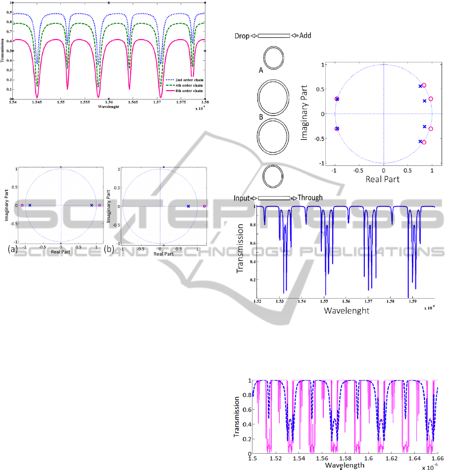
Figure 6: Various orders of single-channel SCISSOR filter
imposed by Thue-Morse sequence (
waveguide
n
=1.5,
ring
n
=3,
c
=0.8,
l
=20µm,
=50(µm)
-1
,
a
r
=10µm,
b
a
rr
,
=0.1).
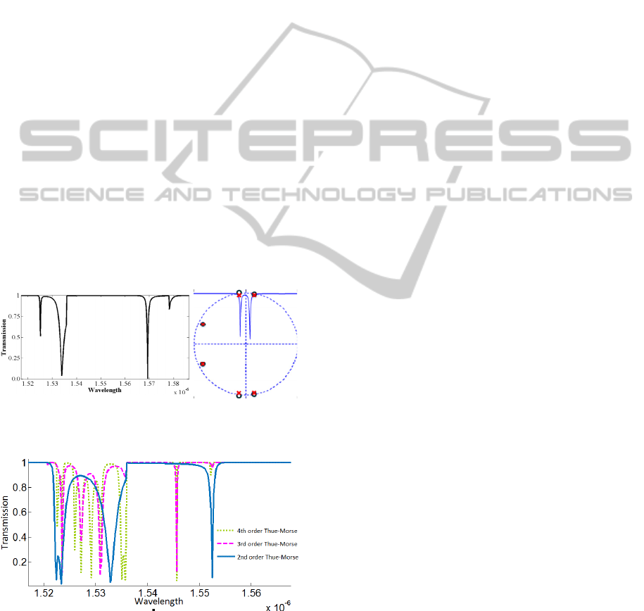
Figure 7: Pole-zero diagram corresponding to distinct basic
building blocks of single channel SCISSOR (a) all pass
filter with circumference equal to twice the unit delay
length (b) single waveguide ring-resonator with
circumference equal to the unit delay length.
case. The final pole-zero diagram is the same as each
basic building block but with higher order individual
pole-zero pairs, depending on the order of system.
Zeros in the corresponding pole-zero diagram for
each CROW block lie on the unit circle for lossless
case and hence critical coupling will occur, on the
other hand considering loss moves all the zeros
outside the unit circle and critical coupling will not
happen. For an active CROW with overall gain all the
zeros lie inside the circle, resulting a minimum phase
system without any critical coupling. As it is evident
from Figure 8, each pole-zero pair cuts a notch in
transmission spectra. The bandwidth of each notch
corresponds to the angular distribution of the pole and
zero and the separation between them determines the
ripple-edge roll-off speed, smaller separation makes
the notches sharper. There is a trade-off between
these parameters, faster roll-off makes the poles
closer to the unit circle and the bandwidth of notch
narrower (Darmawan et al., 2007). The first and
second order two-dimensional structure reveals sharp
ripples and narrow stop bands in the transmission
spectra. Figure 8 features a band-pass filter and
Figure 9 resembles a superior filter of that. The
folding poles and zeros severely suppress the low
frequencies and higher frequencies face more deep
notches, with steeper edge roll-off, this means a better
band-pass shape.
Figure 8: First stage of second order Thue-Morse imposed
dual-ring double-channel SCISSOR structure, pole-zero
diagram with their corresponding transmission spectra (
n
=1.44,
a
l
=20 µm,
b
l
=40 µm,).
Figure 9: Transmission spectra for the first [blue] and
second [pink] order Thue-Morse imposed dual-ring double-
channel SCISSOR structure.
4 APODIZATION
All the investigated structures up to now have the
same value of coupling coefficient. In digital filter
design, a usual method to optimize filter performance
is apodization or windowing. In optical filter design,
apodization means changing coupling coefficient
PHOTOPTICS2015-InternationalConferenceonPhotonics,OpticsandLaserTechnology
106
values from one cell to another based on a windowing
function. In this section, we will employ this method.
The following apodization function expresses
Hamming window
2i
(i) cos( )
i0,1,N1
0.54
0.45
c
N
(17)
Where
N
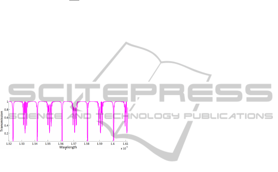
is the size of the structure. As shown in
Figure 7, the apodized structure can realize the
function of a very narrow filter with an FWHM equal
to 0.3 nm. This behavior achieved at a cost of
increased ripples near low frequencies. It must be
considered that an apodized filter performs as an
architecture with reduced number of rings (Capmany
et al., 2007).
Figure 10: Transmission spectra for the second order, Thue-
Morse imposed dual-ring double-channel SCISSOR
structure with coupling coefficients apodized through the
Hamming window.
5 CONCLUSIONS
In this paper, we investigated the ways to attain
higher performance filters with respect to the
conventional ring-resonator based filters. Multiband
response emerged by using Thue-Morse class ring-
resonators. We studied Thue-Morse based optical
structures in the Z-domain and presented the
transmission spectra along with pole-zero diagrams to
provide the framework of an optimal filter design.
The proposed filter enhanced after employing
hamming function, demonstrating that coupling
coefficient and radius engineering can lead to an
optimum design. It would be interesting to use this
approach in ultrahigh order filter design.
REFERENCES
Brlek, S. (1989). Enumeration of factors in the Thue-Morse
word. Discrete Applied Mathematics, 24(1), 83-96.
Capmany, J., Domenech, J., & Muriel, M. (2007).
Apodized coupled resonator waveguides. Optics
express, 15(16), 10196-10206.
Chamorro-Posada, P., Fraile-Pelaez, F. J., & Diaz-Otero, F.
J. (2011). Micro-ring chains with high-order
resonances. Journal of Lightwave Technology, 29(10),
1514-1521.
Darmawan, S., Landobasa, Y. M., & Chin, M.-K. (2007).
Pole–Zero Dynamics of High-Order Ring Resonator
Filters. Journal of Lightwave Technology, 25(6), 1568-
1575.
Dong, P., Feng, N.-N., Feng, D., Qian, W., Liang, H., Lee,
D. C., . . . Toliver, P. (2010). GHz-bandwidth optical
filters based on high-order silicon ring resonators.
Optics express, 18(23), 23784-23789.
Heebner, J. E., Chak, P., Pereira, S., Sipe, J. E., & Boyd, R.
W. (2004). Distributed and localized feedback in
microresonator sequences for linear and nonlinear
optics. JOSA B, 21(10), 1818-1832.
Kaalund, C. J., & Peng, G.-D. (2004). Pole-zero diagram
approach to the design of ring resonator-based filters for
photonic applications. Journal of Lightwave
Technology, 22(6), 1548.
Lenz, G., Eggleton, B., Giles, C., Madsen, C., & Slusher,
R. (1998). Dispersive properties of optical filters for
WDM systems. Quantum Electronics, IEEE Journal of,
34(8), 1390-1402.
Liu, N.-h. (1997). Propagation of light waves in Thue-
Morse dielectric multilayers. Physical Review B, 55(6),
3543.
Madsen, C. K., & Zhao, J. H. (1999). Optical filter design
and analysis: Wiley-Interscience.
Oppenheim, A. V., Schafer, R. W., & Buck, J. R. (1989).
Discrete-time signal processing (Vol. 2): Prentice Hall
Englewood Cliffs.
Park, S., Kim, K.-J., Kim, I.-G., & Kim, G. (2011). Si
micro-ring MUX/DeMUX WDM filters. Optics
express, 19(14), 13531-13539.
Rostami, A., & Matloub, S. (2004). Multi-band optical
filter design using Fibonacci based quasiperiodic
homogeneous structures. Paper presented at the Radio
Science Conference, 2004. Proceedings. 2004 Asia-
Pacific.
Rostami, A., & Rostami, G. (2005). Optical transmission
properties of light propagation through Fibonacci-class
ring-resonators. The European Physical Journal B-
Condensed Matter and Complex Systems, 47(1), 137-
143.
ANovelMultibandFilterDesignbasedonRingResonatorsandDSPApproach
107
