
Model-driven Development for User-centric Well-being Support
From Dynamic Well-being Domain Models to Context-aware Applications
Steven Bosems and Marten van Sinderen
Faculty of Electrical Engineering, Mathematics and Computer Science, University of Twente, Enschede, The Netherlands
Keywords:
Domain Modeling, Model Driven Design, Model Transformations, Well-being, Context-aware Applications.
Abstract:
Applications that can use information obtained through device sensors to alter their behavior are called context-
aware. Design and development of such applications is currently done by modeling the application’s context
or by using novel requirements engineering methods. If the application is to support the user’s well-being,
these methods fall short due to their technical focus. We propose a model-driven approach that deals with the
specifics of the well-being domain by using a DSL that captures the user’s personal well-being context. The
development method is user-centric, rather than technology focused. Initial user experiments show promising
results.
1 INTRODUCTION
Throughout the years, an increase in the amount of
available sensors in smartphone devices can be ob-
served. Even low-end models are equipped with a
wide array of means to collect data. With this data
available, applications that can derive information
from it to alter their run-time behavior are growing
in popularity. (Dey, 2001) defines such context infor-
mation as “any information that can be used to char-
acterize the situation of an entity.” Applications that
can use context information to enhance their services
are called context-aware. Examples are alterations
of the application’s behavior when the user’s loca-
tion changes or changes in the use of external services
when new services become available.
One domain in particular benefiting from this
context-aware nature, is that of well-being. Although
closely related to health-care, which is defined as “ef-
forts made to maintain or restore health especially by
trained and licensed professional” (Merriam-Webster,
2014), well-being concerns the improvement of one’s
health and overall state of happiness without a prede-
fined treatment plan or professional guidance.
Developers working on context-aware well-being
systems face two challenges: (i) the application has
to cope with a continuously changing system environ-
ment at run-time, which can not be fully predicted at
design time, and (ii) well-being systems are highly
personal, so development has to be user centric.
Our contribution to the field of development of
context-aware well-being systems consists of three
parts. Firstly, we have created a DSL that allows us
to capture specifics of the well-being domain. Sec-
ondly, we have developed a model-driven approach
for application development that leverages this DSL.
This method is supported by model transformations
and tools. Thirdly, we have applied our method to
several cases to demonstrate it works and results in an
improved development process. This paper contin-
ues work by (Bosems and van Sinderen, 2014a) and
(Bosems and van Sinderen, 2014b).
The rest of this paper is structured as follows: sec-
tion 2 provides a motivating example, and section 3
lists related work. In section 4 we discuss the struc-
ture of our DSL for the well-being domain. Section 5
lists the technologies used in our model-driven pro-
cess, section 6 provides information about the tool
support offered, section 7 explains our model trans-
formation process, for which use cases are discussed
in section 8. Section 9 provides concluding remarks
and directions for future work.
2 MOTIVATING EXAMPLE
Our example is based on the “Activity Coach” (op
den Akker, H. et al., 2012). The application runs on
a smart-phone and monitors the user during the day.
Its goal is to improve the user’s physical well-being,
which is done by managing the his/her activity. The
application coaches him/her to be more active when
425
Bosems S. and van Sinderen M..
Model-driven Development for User-centric Well-being Support - From Dynamic Well-being Domain Models to Context-aware Applications.
DOI: 10.5220/0005339204250432
In Proceedings of the 3rd International Conference on Model-Driven Engineering and Software Development (MODELSWARD-2015), pages 425-432
ISBN: 978-989-758-083-3
Copyright
c
2015 SCITEPRESS (Science and Technology Publications, Lda.)
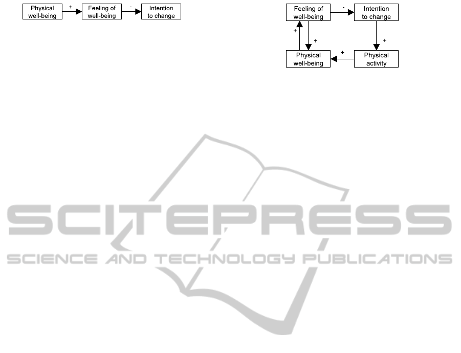
Figure 1: A simple causal path.
s/he is passive, or slowing him/her down if s/he un-
dertakes too much activity early on in the day. The
application works unobtrusively. The user’s activity
progress is evaluated regularly, and feedback is pro-
vided to guide the user. Other important factors for
the Activity Coach are the user’s motivation and in-
tention to change his/her daily behavior. Physical fac-
tors such as cardiovascular fitness and body composi-
tion should also be taken into account, as well as heart
rate and blood pressure. Relations between these fac-
tors may not be intuitively clear.
3 RELATED WORK
The development of context-aware applications has
widely been recognized as demanding. Several so-
lution directions exist.
Firstly, (Seyff, N. et al., 2008) recognize that con-
tinuous changes in the environment around the user
will cause changing user requirements: requirements
are context dependent. The authors try to solve this
problem by incorporating in-situ requirements engi-
neering in the design process: a requirements engi-
neer follows users while they use a prototype version
of the application under development, noting down
new requirements and the respective context as they
arise. This method is labor intensive.
Secondly, runtime models are proposed as a so-
lution (Alferez and Pelechano, 2012), (Salifu, M. et
al., 2007), (Sitou and Spanfelner, 2007), (Qureshi and
Perini, 2010). Approaches in this direction capture
either requirements or context information in models
which can be interpreted by the application at run-
time. If a situation of context change occurs, these
models are reevaluated. The internal models can be
adapted to reflect the updated context when needed,
or the desired behavior can be derived from the re-
quirements captured in the models. These models,
however, expect extensive context knowledge and the
ability to predict required information.
Thirdly, authors propose to use model-driven ap-
proaches as a tool for development (Maiden, N. A.
M. et al., 2004), (Mu
˜
noz, J. et al., 2006). These ap-
proaches, however, are aimed at solving the techno-
logical problems of context-awareness, disregarding
the future end-user. We propose a method that is cen-
tered around the user, thus being better able to cope
with changes in the personal context.
Finally, the modeling of the context of the appli-
Figure 2: Two causal loops.
cation is given as a solution direction (Henricksen, K.
et al., 2002), (Henricksen and Indulska, 2006). By
capturing every aspect of the (technical) context, the
development of context-aware applications should be-
come easier. However, while this approach might suf-
fice for applications with a clearly defined context (a
tour guide for example), or systems that deal with al-
tering, but predictable contexts (one location with ac-
tors moving through it such as a smart room), this
will not work for our intended goal: the domain of
personal well-being is highly dynamic and not all re-
lations among the different context elements are fully
understood.
4 DYNAMIC WELL-BEING
DOMAIN MODELS
In this section, we will provide a short description on
the structure of Dynamic Well-being Domain Models
(DWDMs). DWDMs consist of three types of mod-
eling elements: i) variables, ii) causalities, and iii)
norms. Figure 3 shows a DWDM for the Activity
Coach.
4.1 Variables
In DWDMs, variables represent context factors and
well-being conditions. Variables have several at-
tributes: (i) annotations, (ii) unit of measurement, (iii)
processing type, and (iv) measurement scale.
A variable’s annotation captures if we, consider-
ing the current state of the sensor techniques, can ob-
serve the variable value, or that the variable can be
influenced by the system directly. For example, it is
possible to measure a user’s “Physical activity” us-
ing accelerometers, making it an observable variable.
The user’s “Intention to change” on the other hand
can not be obtained through sensors, but should be
deduced by obtaining additional information, and rea-
soning about the variable’s value. Variables that can
be controlled directly by the system are more rare, as
they tend to include only those context variables that
are part of actuators. An example of such a variable
is “Valve position,” modeling the current position of a
radiator valve in a temperature control system.
MODELSWARD2015-3rdInternationalConferenceonModel-DrivenEngineeringandSoftwareDevelopment
426
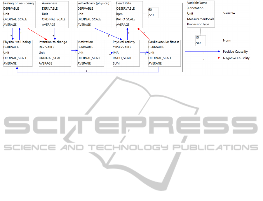
Figure 3: DWDM for the Activity Coach.
Variables may have a unit of measurement. Un-
like the annotation, not all variables have this prop-
erty: it is most common in variables that are observ-
able. Units of measurement can be categorized as ei-
ther being absolute (the value stands on it’s own, such
as the user’s blood pressure), or relative (the value is
relative to an other unit of measurement, such as the
concept of cardiovascular fitness). Furthermore, units
can either be time dependent (measurement of events
occurring over a certain period of time, such as heart
rate in beats per minute), or time independent.
The processing type of a variable affects the way
a variable value should be processed. Variable value
reading stands can stand on themselves, or can require
additional processing. An example of the former is
the user’s current location, telling us something about
the current context. Values of variables in the latter
category require multiple sensor readings to reason
about their value, such as the user’s speed of travel-
ing, for which we need at least two measurements of
the user’s location (to calculate the traveled distance),
and the time required to travel between these.
Lastly, we distinct four types of measurement
scales (Stevens, 1946) on which the values of vari-
ables can be measured. Using these, we can deter-
mine what value calculations may be performed. The
nominal scale only allows for equality comparison,
an ordinal scale makes it possible to create a ranking
among variables, the interval scale adds detail regard-
ing the size difference between measurements, and
the ratio scale adds knowledge of a non-arbitrary 0
point.
4.2 Causalities
DWDMs consist of model elements that capture real-
world context elements, their properties, and relations
between them. In DWDMs, these relations are causal
relations. They have two properties. The first is the
direction. A relation has a source and a target, indicat-
ing which variable is affected by which other variable.
By looking at the direction, we can reason about how
variables are affected throughout the DWDM.
The second property is the polarity of the relation,
i.e. if the causal relation is positive or negative. A
positive causal relation from source to target indicates
that an increase in the former will cause an increase in
the latter; no guarantee about the time it will take to
reach this increase can be given, nor does the relation
say anything about the amount of change. The nega-
tive causality indicates that an increase in the source
will result in a decrease in the target.
By combining causal relations, we can create
paths. A path is sequence of one or more causalities,
connecting two or more variables. A path does not
contain a given variable twice. As per the direction
of the relations, a path connects its start and ending
variables indirectly. This allows us to reason about
indirect effects. This can be done in two directions.
Observe the picture in Figure 1. If we are to measure
variable A and we see an increase in A, we can rea-
son that this change will traverse through the system,
affecting both B and C, increasing B and decreasing
C. We call this process forward reasoning. On the
other hand, if we were to measure variable C and see
a decrease in it, we can reason that this decrease was
caused by an increase in variable B, which in turn is
caused by an increase in variable A. This process is
called reverse reasoning.
In addition to paths, we can create loops. We de-
fine a loop as being a path in the model of which the
starting and ending variable are the same. In Figure 2,
we see an example causal graph with two loops.
The first loop we can identify, is Feeling of well-
being – Physical well-being – Feeling of well-being.
This loop contains only positive causalities. As such,
an increase in Feeling of well-being, causes an in-
crease in Physical well-being, which in turn causes an
increase in Feeling of well-being. This models an ex-
ponential growth and is called a reinforcing loop. The
second loop consists of Feeling of well-being – In-
tention to change – Physical activity – Physical well-
Model-drivenDevelopmentforUser-centricWell-beingSupport-FromDynamicWell-beingDomainModelsto
Context-awareApplications
427
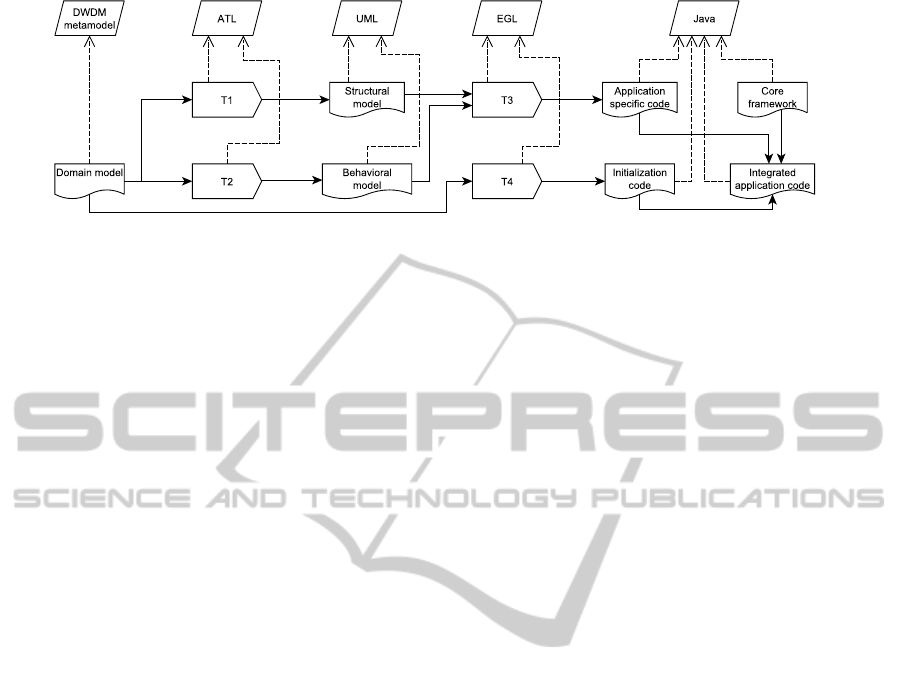
Figure 4: Development process and relations between models.
being – Feeling of well-being. In this loop we see both
a positive and a negative causal relation: an increase
in Feeling of well-being causes an decrease in Inten-
tion to change, resulting in a decrease in Physical ac-
tivity, causing a decrease in Physical well-being, de-
creasing the Feeling of well-being. This last decrease
causes an increase in the Intention to change. Such
a balancing loop models a stable situation, as the in-
crease of a variable eventually causes that same vari-
able to decrease again.
4.3 Norms
(Merriam-Webster, 2014) defines a norm as “a set
standard of development or achievement usually de-
rived from the average or median achievement of a
large group.” We see a variable’s norm as being a
normal variable value for the general population; a
norm might not always hold for an individual. For
example, the norm for a resting heart rate is 60-100
BPM, but some athletes may have heart rates as low
as 40-50 BPM. Norms have a range, with the values in
this interval being considered healthy. Norms can be
obtained from medical literature and through expert
interviews.
5 TECHNOLOGIES USED
Model Development. For the development of the
meta-models and editors, we have selected the Eclipse
Modeling Framework (EMF). These plug-ins for the
Eclipse IDE are widely used for meta-model develop-
ment on the Eclipse platform. The meta-models cre-
ated using EMF are in the ecore format, EMF provid-
ing means for the generation of editors for these.
Editor Development. The Graphical Modeling
Framework (GMF) was used to create the graphical
editors for our DSL. GMF provides us with a set of
Eclipse plug-ins, allowing for the structured devel-
opment of graphical editors for ecore-based models.
To be able to graphically edit UML models, we in-
tegrated the UML2Tools plug-in when building the
Eclipse-based editor.
Model Transformation. In our development pro-
cess, we identify both model-to-model and model-to-
text transformations. We have opted for two sepa-
rate solutions for these. For the former, we selected
the Atlas Transformation Language (ATL) as the best
suited candidate. The ATL editor and transformation
engine are provided as an Eclipse plug-ins. ATL out-
performs other model transformation engines and has
an active community (van Amstel, M. et al., 2011).
For the model-to-text transformations, we opted for
the use of the Epsilon Generation Language (EGL).
Core Framework. At the center of our executable
application, we have a core framework implemented
in Java. This framework is based on the architecture
discussed by (Bosems, S. et al., 2013). It contains
components that are deemed reusable and common
for context-aware well-being applications. The ap-
plication development process discussed in this paper
extends this core framework with components that are
specific to a single application.
6 TOOL SUPPORT
We have created a tool that supports the process in
depicted in Figure 4. This was also described in
(Bosems and van Sinderen, 2014b). Firstly, a domain
model (which is an instance of the DWDM meta-
model) that is specific to the application under de-
velopment is created using the DWDM model editor.
This application specific DWDM is a subset of a ref-
erence DWDM such as the one described by (Bosems,
2014), containing only variables relevant to the prob-
lem domain. A technology expert adds information
regarding the hardware capabilities through variable
annotations. When performed for our example, this
results in the model depicted in Figure 3.
MODELSWARD2015-3rdInternationalConferenceonModel-DrivenEngineeringandSoftwareDevelopment
428
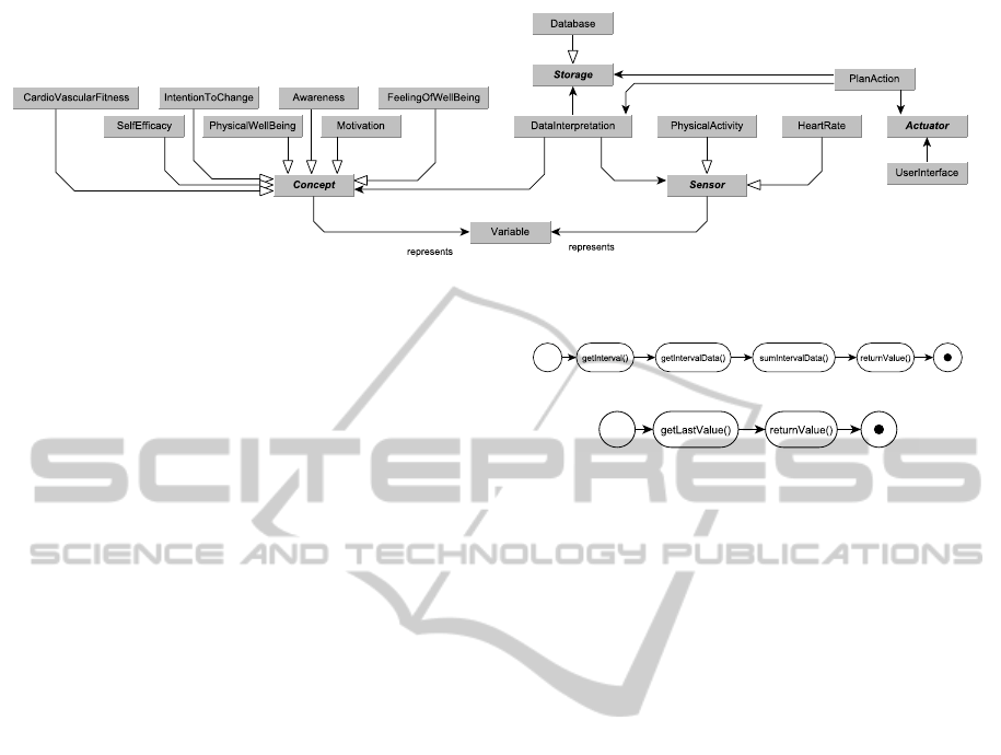
Figure 5: UML Class diagram for the Activity Coach.
Secondly, UML models are generated using
model transformations. These models are refined by
a software engineer to include bindings specific to
the implementation platform. Finally, code is gen-
erated. This code partially originates from the appli-
cation specific DWDM, partially it is generated from
the software models. The generated code is added to
a core framework to form the application that can be
run on the intended platform.
7 MODEL TRANSFORMATIONS
We have four transformations supporting our model-
driven process (Figure 4). We will discuss each of
these in this section. The source models for the
model transformations are DWDM models, discussed
in more detail by (Bosems and van Sinderen, 2014b).
7.1 Structure Generation
Using model transformation T1, we can generate the
application structure model. In this transformation,
we map a DWDM to a UML Class diagram. For the
generation of the static application structure, we are
primarily interested in variables and their properties.
When mapping the DWDMs to Platform Indepen-
dent Model (PIM) level models, the variable annota-
tions dictate the static application structure. For these
diagrams, we assume a basic structure such as iden-
tified by (Bosems, S. et al., 2013). If the annotation
is observable, a class extending the Sensor class is
added to the model, if the annotation is deducible,
a class extending the Concept class is added, and a
variable with the controllable annotation causes the
creation of a class extending the Actuator class.
When applying T1 to the DWDM in Figure 3, we
obtain the class diagram shown in Figure 5.
(a) Time dependent behavior
(b) Time independent behavior
Figure 6: UML Activity diagrams for data processing.
7.2 Behavior Generation
Application behavior is more diverse and complex
than application structure. The derivation of this be-
havior is based on several elements of the DWDMs
and is done in transformation T2 which maps DWDM
elements to UML Activity Diagrams.
7.2.1 Behavior from Variables
Besides the annotation, variables have other proper-
ties; these affect the application’s behavior.
Firstly, the variable’s unit of measurement affects
the way data is processed. If the variable is time
dependent, multiple sensor readings will have to be
combined, while time independent values can be used
without additional calculations. Results of these are
found in Figure 6.
Secondly, there are two processing types. For the
first, we have to take the average value of the vari-
able value. This is required for the application to be
able to reason about the trend of a variable value. The
second type of processing requires us to sum the vari-
able values obtained. This is needed for variables of
a time dependent nature, such as the Physical activity
over the day: the obtained movement data has to be
summed in order to gain the total amount of move-
ment over the day.
Finally, the measurement scale dictates the granu-
larity of feedback that can be given: a higher class of
measurement scale the application can provide more
detailed feedback. For example, while it can only be
reasoned if the level of cardiovascular fitness (ordinal
Model-drivenDevelopmentforUser-centricWell-beingSupport-FromDynamicWell-beingDomainModelsto
Context-awareApplications
429

scale) increased or decreased, quantifying this value
is not possible. The feedback given to the user can
thus only be to increase or decrease his/her cardiovas-
cular fitness. However, it is possible to see if a person
was twice as active as the day before (ratio scale), not
just more or less active.
7.2.2 Behavior from Relations
The causal relations described here have two effects
on the behavior diagrams created from them. Firstly,
we can calculate the values for deducible variables
through reverse causal reasoning. Such application
components (extending the Concept class) include
the following method:
double ge t V a l u e ( V a r i a b l e s t a r t ) {
double r e s ;
f o r e a c h ( i i n v a r . i n c o m i n g R e l a t i o n s ) {
V a r i a b l e s r c = i . s o u r c e ;
5 i f ( s r c != s t a r t ) {
r e s += i . s o u r c e . g e t V a l u e ( s t a r t ) ;
}
}
r e t u r n r e s ;
10 }
Listing 1: Obtaining the value of a derivable variable.
This process will stop when variable is reached which
is observable. Components representing such vari-
ables extend the Sensor class and have a getValue()
method which returns the sensor value.
Secondly, the relations can be used for causal rea-
soning. Using this quality, we can make the applica-
tion under development reason too. The behavior that
can be mapped to UML Activity diagrams is goal rea-
soning. By performing a breadth-first search over the
DWDM, starting from one initial application goal, it
can be determined what should happen to the values
of other variables in the DWDM, i.e. if they should
be increased or decreased. For example, if the goal is
to increase “Physical well-being,” changes would in-
clude increasing “Cardiovascular health” and increas-
ing “Physical activity”. As the latter is an observable
variable, the application can provide feedback in or-
der to increase this variable.
Finally, when using the two types of loops identi-
fied, we can reason about the degree of change that
will be happening in the user’s well-being context,
and predict future trends. Loops can not be exploited
when deducing variable values.
7.2.3 Behavior from Norms
The norms captured in the DWDMs are mapped to
if-the-else constructs in the UML Activity dia-
grams to control the boundary conditions for the ap-
plication: although an overall goal graph has been
generated through goal reasoning to obtain a certain
overall target, the norms dictate immediate feedback:
a goal might indicate that the user should move more,
but for the current day the user has already reached his
quota. In this case, the norm value overrules the goal,
and as such steers the feedback given. We can say that
the causal relations and the resulting goals prescribe
the overall system operations and feedback, whereas
norms regulate real-time feedback and interventions.
7.3 PSM Creation
The models (with the exception of the initialization
code) generated so far are at the level of Platform In-
dependent Models (PIMs): they are generic with re-
gard to an implementation platform. To be able to
generate code from them, platform bindings and ad-
ditional information is required.
Although bindings to the implementation platform
are not straight forward, as matching Sensor classes
based on name is not directly possible, it is possible
to partially support this in the future: by providing the
developer with means to manually map Sensor class
names to API names, the methods in the Sensor class
can be supplied with mappings to API calls. However,
additional non-functional requirements that are to be
satisfied by the application, such as scalability, safety,
and responsiveness, are not captured in the CIMs or
PIMs. These are to be added manually.
7.4 Code Generation
By using model-to-text transformation T3, as shown
in Figure 4, we can combine the information de-
scribed in the structural and behavioral PSMs and
generate application code. This application code con-
tains those elements specific to the domain described
in the domain model such as code to interface with
those sensors needed to obtain context information,
and code to calculate the values of context elements
that can not be directly read by sensors.
As code generation has become common practice,
we will not elaborate on this further.
7.5 Initialization Generation
Figure 4 shows that the application under develop-
ment consists of three elements: (i) a core frame-
work, (ii) an application specific part containing code
to, among others, interface with sensors, and (iii) ini-
tialization code. This last element is obtained through
model-to-text transformation T4.
MODELSWARD2015-3rdInternationalConferenceonModel-DrivenEngineeringandSoftwareDevelopment
430

As mentioned earlier, the application requires
graph algorithms such as breadth-first search to obtain
information and to guide the application’s behavior.
The graph information which was present in the do-
main model is, however, lost when transforming the
structural and behavioral models. In order to be able
to use the graph structure, it should be translated to
the application’s data model.
In the internal model, we store: (i) the variables
present in the DWDM with all their properties, and
(ii) the causal relations between the variables. This
information is captured by instantiating the Variable
class and the Causality class. These instances are
then stored and used for goal reasoning.
7.6 Application Construction
With all code elements generated or created, they can
be assembled. This is currently done manually. The
core framework is taken as a basis, the files contain-
ing the application specific code are added in separate
folders. These files are evaluated at run-time and their
classes instantiated through Java Reflection.
8 APPROACH APPLICATION
AND DISCUSSION
In this section, we will describe the application of our
approach in four experiments and discuss the results.
8.1 Application
Our modeling and design approach has been applied
in several settings to test their usefulness. Firstly, the
DWDM editor tool was used to facilitate the discus-
sion regarding the well-being domain among experts
in the fields of physical and mental well-being. After
explaining the modeling language, the experts could
discuss and reason about the domain elements in their
own field, and make connections to the other domain.
This small scale workshop was facilitated by one of
the authors of this paper, the resulting model can be
found at (Bosems, 2014). Validation of this overall
well-being model is currently being planned.
Secondly, a master graduation student was pro-
vided the DWDM editor to model the well-being
domain and test the design process. No model-
transformations were available, so further develop-
ment of the application development was done by
hand. The use of DWDMs was seen as useful to gain
insight in the technical application requirements. Re-
search was performed in to strategies for the selection
of “relevant” domain variables, given a certain goal
variable. Two strategies were identified and presented
by (Soriano Perez, 2014).
Thirdly, four students in a postgraduate course on
MDE were given the task to design an Activity Coach.
They were given the DWDM editor, and implementa-
tions of model transformations T1 and T2, allowing
them to generate PIM level models, as discussed in
sections 7.1 and 7.2. The time limit for the experiment
was 90 minutes. Results showed that the participants,
i.e. software engineers, were highly technology fo-
cused, not fully exploiting the domain knowledge and
models; participants were aimed at creating a soft-
ware solution, rather than thinking of the specifics of
the domain the application would be to focus in when
developed. Due to this narrow focus, DWDMs were
not used correctly. Additional experiments are needed
for further validation.
Finally, one of the authors compared the usage
of the process and model transformations discussed,
with the development of an application from scratch.
It was found that a full development of an applica-
tion using the structured method was faster than the
manual creation of an application. It should, how-
ever, be noted that due to in-depth knowledge of the
“desired” application structure, behavior and possible
implementation, the manual design and development
of the system was faster than what could be expected
when dealing with a new type of application. As such,
this experiment can be considered biased in that the
time required for the manual construction was lower
than what can be expected when the application struc-
ture and behavior is unknown.
8.2 Discussion
Although results show that our approach for the well-
being domain has benefits over traditional software
engineering models, and that these benefits can be ex-
ploited when they are used to guide the design and de-
velopment of well-being applications, there are some
considerations to be taken into account.
Firstly, the current process does not include steps
for the creation of a user interface. For this type of ap-
plication, the presentation to and interaction with the
user is of key importance; if the UI does not perform
adequately, the user will disregard the application.
Secondly, the current DWDM editor lacks features
that may improve usability. For example, the ability
to group, merge or hide modeling elements would in-
crease developer productivity.
Finally, the process relies on the input DWDM to
be valid. If this model is not valid, the resulting appli-
cation will be flawed too.
Model-drivenDevelopmentforUser-centricWell-beingSupport-FromDynamicWell-beingDomainModelsto
Context-awareApplications
431

9 CONCLUSIONS AND FUTURE
WORK
Even though the domain of person-centric, context-
aware well-being is rapidly growing, modeling and
development methods dealing with the specific chal-
lenges of these applications are still scarce. To bridge
the gap between domain and technology experts, we
have created a modeling language that allows stake-
holders to capture the relevant domain variables and
the causal relations between them, while focusing on
the future user rather than the technology used. The
resulting model can then serve as the input for a model
transformation supported development process. We
have illustrated this with a motivating example.
Through four case studies, we have shown that the
proposed process can indeed speed up application de-
velopment, but does require the right mindset from
the domain and technology experts. Future work in-
cludes the improvement of current tool support to in-
crease designer productivity. Furthermore, the refer-
ence DWDM should be valid for it to be a useful de-
velopment starting point. This validation should be
conducted among experts in the fields of physical and
mental well-being.
ACKNOWLEDGEMENTS
This publication was supported by the Dutch national
program COMMIT (project P7 SWELL).
REFERENCES
Alferez, G. H. and Pelechano, V. (2012). Dynamic evolu-
tion of context-aware systems with models at runtime.
In 15th Int. Conf. on Model Driven Engineering Lan-
guages and Systems, volume 7590 of Lecture Notes in
Computer Science, pages 70–86.
Bosems, S. and van Sinderen, M. (2014a). Models in the
Design of Context-Aware Well-Being Applications. In
On the Move to Meaningful Internet Systems, volume
8842 of Lecture Notes in Computer Science, pages
37–42. Springer.
Bosems, S. and van Sinderen, M. J. (2014b). Improving
context-aware applications for the well-being domain:
Model-driven design guided by medical knowledge.
In 3rd Int. Conf. on Sensor Networks, pages 397–403.
SciTePress.
Bosems, S. e. a. (2014). Dynamic Domain Model for Well-
Being. http://wwwhome.ewi.utwente.nl/∼bosemss/
2015/modelsward/wellbeing.png.
Bosems, S. et al. (2013). COMMIT SWELL D1.2 Overall
architecture. Technical report, COMMIT/SWELL.
Dey, A. K. (2001). Understanding and Using Context. Per-
sonal and Ubiquitous Computing, 5(1):4–7.
Henricksen, K. and Indulska, J. (2006). Develop-
ing context-aware pervasive computing applications:
Models and approach. Pervasive and mobile comput-
ing, 2(1):37–64.
Henricksen, K. et al. (2002). Modeling Context Information
in Pervasive Computing Systems. In Pervasive Com-
puting, volume 2414 of Lecture Notes in Computer
Science, pages 79–117. Springer.
Maiden, N. A. M. et al. (2004). Model-Driven Require-
ments Engineering: Synchronising Models in an Air
Traffic Management Case Study. In 16th Int. Conf. on
Advanced Information Systems Engineering, volume
3084, pages 368–383. Springer.
Merriam-Webster (2014). http://www.merriam-
webster.com. Last accessed on Nov. 03, 2014.
Mu
˜
noz, J. et al. (2006). Requirements Engineering for
Pervasive Systems. A Transformational Approach.
In 14th IEEE Int. Requirements Engineering Conf.,
pages 351–352.
op den Akker, H. et al. (2012). Development and evaluation
of a sensor-based system for remote monitoring and
treatment of chronic diseases - the continuous care &
coaching platform. In 6th Int. Symposium on eHealth
Services and Technologies, pages 19–27. SciTePress.
Qureshi, N. A. and Perini, A. (2010). Requirements En-
gineering for Adaptive Service Based Applications.
In 18th IEEE Int. Requirements Engineering Conf.,
pages 108–111.
Salifu, M. et al. (2007). Specifying monitoring and switch-
ing problems in context. In 15th IEEE Int. Require-
ments Engineering Conf., pages 211–220.
Seyff, N. et al. (2008). Mobile Discovery of Requirements
for Context-Aware Systems. In 14th Int. Working
Conf. on Requirements Engineering: Foundation for
Software Quality, pages 183–197.
Sitou, W. and Spanfelner, B. (2007). Towards requirements
engineering for context adaptive systems. In 31st An-
nual Int. Computer Software and Applications Conf.,
volume 2, pages 593–600.
Soriano Perez, C. S. (2014). Context Aware Systems in
Well-Being: From user needs to software architecture.
Master’s thesis, Universitat Politecnica de Valencia.
Stevens, S. S. (1946). On the Theory of Scales of Measure-
ment. Science, 103(2684):677–80.
van Amstel, M. et al. (2011). Performance in model trans-
formations: experiments with ATL and QVT. In 4th
Int. Conf. on Theory and Practice of Model Transfor-
mations, volume 6707 of Lecture Notes in Computer
Science, pages 198–212. Springer.
MODELSWARD2015-3rdInternationalConferenceonModel-DrivenEngineeringandSoftwareDevelopment
432
