
Real-time Material Transformation
using Single Frame Surface Orientation Imager
Toru Kurihara
1
and Shigeru Ando
2
1
School of Information, Kochi University of Technology, 185 Miyanokuchi, Kami City, Kochi, Japan
2
Department of Information Physics and Computing, University of Tokyo, 7-3-1 Hongo, Bunkyo-ku, Tokyo, Japan
Keywords:
Material Perception, VFX, Normal Vector Map, Photometric Stereo.
Abstract:
In this paper, we propose real-time reflectance transformation system using correlation image sensor and four
LEDs. The reflectance transformation system changes object appearance into different materials one and
displays it in the monitor. We have developed real-time surface orientation imager to add specular component
according to captured normal vector map for reflectance transformation. Surface orientation of the object
is encoded into amplitude and phase of the reflected light intensity by using phase shifted blinking LEDs,
The correlation image sensor, provided by us, demodulates those amplitude and phase in each pixel during
exposure time. Therefore, the surface orientation is captured by single frame, which can be applied to moving
object. We developed reflectance transformation system using surface orientation captured by our real-time
surface orientation imager. We demonstrated that the system provides relighting and changing reflectance
property in real-time.
1 INTRODUCTION
Lighting and reflectance properties are important for
material perception. Malzbender et. al. proposed
reflectance transforming technique based on normal
directions for enhancing surface detail(Malzbender
et al., 2006). The system makes surface detail more
apparent and amplify surface details, therefore it
helps surface inspection. They proposed to enhance
surface normal details by amplifying high-frequency
variations in surface normals. Wenger et. al. pro-
posed relighting and reflectance transformation sys-
tem with time-multiplexed illumination especially for
facial images (Wenger et al., 2005).
In this paper, we propose real-time reflectance
transformation system, which is useful for visual ef-
fects (VFX) on entertainment system or television
broadcasting program. The proposed system con-
sists of four light sources and correlation image sen-
sor(Ando and Kimachi, 2003). Modulated illumina-
tion encodes surface orientation into amplitude and
phase of the reflected light intensity, and correlation
image sensor demodulates those signals in each pixel
at frame rate(KURIHARA et al., 2012),(Kurihara
et al., 2003),(Kurihara et al., 2005). Based on recon-
structed surface normals, we calculate intensity image
under arbitrary illumination and reflectance param-
eters. Changing Lighting condition and reflectance
transformation affect the reconstructed images imme-
diately.
The following part of this paper describes the
sensing and reflectance transformation principle we
have developed using our 640 ×512-pixel correlation
image sensor, and show experimental results of the
reflectance transformation.
2 REAL-TIME SURFACE
ORIENTATION IMAGER
2.1 Correlation Image Sensor(Ando and
Kimachi, 2003)
The three-phase correlation image sensor (3PCIS) is
the two dimensional imaging device, which outputs
a time averaged intensity image g
0
(x,y) and a corre-
lation image g
ω
(x,y). The correlation image is the
pixel wise temporal correlation over one frame time
between the incident light intensity and three external
electronic reference signals.
The photo of the 640 × 512 three-phase correla-
tion image sensor is shown in Figure 1, and its pixel
structure is shown in Figure 2.
240
Kurihara T. and Ando S..
Real-time Material Transformation using Single Frame Surface Orientation Imager.
DOI: 10.5220/0005357602400245
In Proceedings of the 10th International Conference on Computer Vision Theory and Applications (VISAPP-2015), pages 240-245
ISBN: 978-989-758-089-5
Copyright
c
2015 SCITEPRESS (Science and Technology Publications, Lda.)
Let T be frame interval and f (x,y,t) be instant
brightness of the scene, we have intensity image
g
0
(x,y) as
g
0
(x,y) =
∫
T /2
−T /2
f (x,y,t)dt (1)
Let the three reference signals be v
k
(t) (k = 1,2, 3)
where v
1
(t) + v
2
(t) + v
3
(t) = 0, the resulting correla-
tion image is written like this equation.
c
k
(x,y) =
∫
T /2
−T /2
f (x,y,t)v
k
(t)dt (2)
Here we have three reference signals with one con-
straint, so that there remains 2 DOF for the basis of
the reference signal. We usually choose orthogonal si-
nusoidal wave pair (cos ωt, sinωt) as the basis, which
means v
1
(t) = cos ωt,v
2
(t) = cos(ωt +
2
3
π),v
3
(t) =
cos(ωt +
4
3
π).
Let the time-varying intensity in each pixel be
f (x,y,t) = A(x,y)cos(ωt + ϕ(x, y)) + B(x,y,t). (3)
Here A(x,y) and ϕ(x,y) is the amplitude and phase
of the frequency component ω, and B(x, y,t) is the
other frequency component of the intensity including
DC component. Due to the orthogonality, B(x,y,t)
doesn’t contribute in the outputs c
1
,c
2
,c
3
. There-
fore the amplitude and the phase of the frequency ω
component can be calculated as follows(Ando and Ki-
machi, 2003)
A(x,y) =
2
√
3
3
(c
1
−c
2
)
2
+ (c
2
−c
3
)
2
+ (c
3
−c
1
)
2
(4)
ϕ(x,y) = tan
−1
√
3(c
2
−c
3
)
2c
1
−c
2
−c
3
(5)
From the two basis of the reference signal
(cosnω
0
t,sin nω
0
t), we can rewrite amplitude and
phase using complex equation.
g
ω
(x,y) =
∫
T /2
−T /2
f (x,y,t)e
−jωt
dt (6)
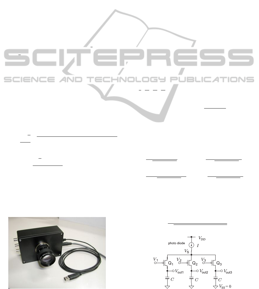
Figure 1: Photograph of Correlation Image Sensor(CIS).
Here ω = nω
0
= 2πn/T . g
ω
(x,y) is the complex form
of the correlation image, and it is a temporal Fourier
coefficient of the periodic input light intensity.
The advantages of the correlation image sensor
are (1) single frame correlation detection, which en-
ables real-time measurement, (2) suppression of noise
which comes from enviromental illumination. So we
adopt correlation image sensor to realize real-time
surface orientation measurement in the uncontrolled
environment.
2.2 Light Sources
To encode surface normal into amplitude and phase of
reflected light intensity signal, we modulate four light
sources at vertices of a square with the frequency ω,
but those phase are different. The phase are set at
those argument of each light sources in xy-plane. The
values are shown in Table 1.
Consider the quadrature phase light sources
s
k
(k = 0,1, 2,3) of fig.3 which are arranged to make
square, and the intensity is modulated by sinusoidal
waves whose frequency is ω, and whose initial phase
is
π
4
,
3π
4
,
5π
4
,
7π
4
. Therefore intensity of each light
source is
S
k
(t) = 1 + cos
ωt +
(2k + 1)π
4
. (7)
Let l
k
(k = 0,1,2,3) be the unit vector cor-
responding to the three light sources direction
whose positions are (L/2, L/2,H), (−L/2,L/2,H),
(−L/2,−L/2,H), (L/2,−L/2, H), respectively.
Then l
k
can be written as
l
0
=
(L/2,L/2,H)
L
2
/2 + H
2
, l
1
=
(−L/2,L/2,H)
L
2
/2 + H
2
, (8)
l
2
=
(−L/2,−L/2,H)
L
2
/2 + H
2
, l
3
=
(L/2,−L/2,H)
L
2
/2 + H
2
(9)
If the equation of an object surface is given explicitly
as:
z = h(x, y) (10)
then a surface normal is given by the vector:
n =
(−h
x
(x,y),−h
y
(x,y),1)
1 + h
x
(x,y)
2
+ h
y
(x,y)
2
(11)
Figure 2: Pixel structure of the correlation image sensor.
Real-timeMaterialTransformationusingSingleFrameSurfaceOrientationImager
241

x
y
z
F
Q
n
4 light
sources
s0
s1
s2
s3
Figure 3: Geometry of quadrature phase light sources and
surface normal.
Table 1: Position and initial phase of light sources
position initial phase (deg)
(
L
2
,
L
2
,H) 45
(−
L
2
,
L
2
,H) 135
(−
L
2
,−
L
2
,H) 225
(
L
2
,−
L
2
,H) 315
where,
h
x
(x,y) =
∂h(x,y)
∂x
, h
y
(x,y) =
∂h(x,y)
∂y
(12)
The object to be analyzed is assumed to have Lam-
bertian reflectance and to be near origin so that the
directions of four light from the whole surface is the
same. Then, the brightness at the position (x, y) can
be written as
I(x, y,t) =
3
∑
k=0
AR(x,y)(l
k
·n(x,y)S
k
(t) (13)
=4AR(x,y)cosψcos Θ(x,y)
+ 2AR(x,y)sin ψsin Θ(x,y)cos(ωt + Φ(x,y))
(14)
where R denotes the surface reflectance index at
(x,y), tanψ =
L
√
2H
, and zenith angle and azimuth an-
gle of the normal vector is Θ, Φ, respectively. Thus
we can obtain the azimuth angle of the normal vec-
tor as the second term phase, and the zenith angle as
the ratio between the first term and second term am-
plitude. Therefore, surface reflectance doesn’t affect
normal vector like photometric stereo method.
3 REFLECTANCE
TRANSFORMATION
We obtain surface normal map by the method de-
scribed in the previous section. Then we use these
information for reflectance transformation. In this pa-
per, we apply Blinn model to confirm real-time sur-
face reflectance transformation principle,
I(x, y) = AR(x,y)(l ·n) + AS(h ·n)
m
(15)
for arbitrary illumination direction l and normal vec-
tor n. Here h is a halfway vector between the viewer
and light-source vectors v, l,
h =
v + l
|v + l|
(16)
4 SYSTEM
To show our principle, we have developed proto-type
system consists of 4 IR(Infra Red) LEDs and correla-
tion image sensor. The correlation image sensor has
640x512 resolution and it works at 15Hz and 30Hz.
We used 15Hz frame rate. The illumination consists
of Osram IR LED (SFH4750) whose wavelength is
850nm. The modulation frequency is set at 210 Hz,
which means 14 times rotating during a single expo-
sure. The distance between each LEDs is 500mm.
The computer captures correlation outputs
through USB2.0 port from the correlation image
sensor, and calculates surface orientation. Then the
system outputs relighting images or the results of
reflectance transformation on monitor.
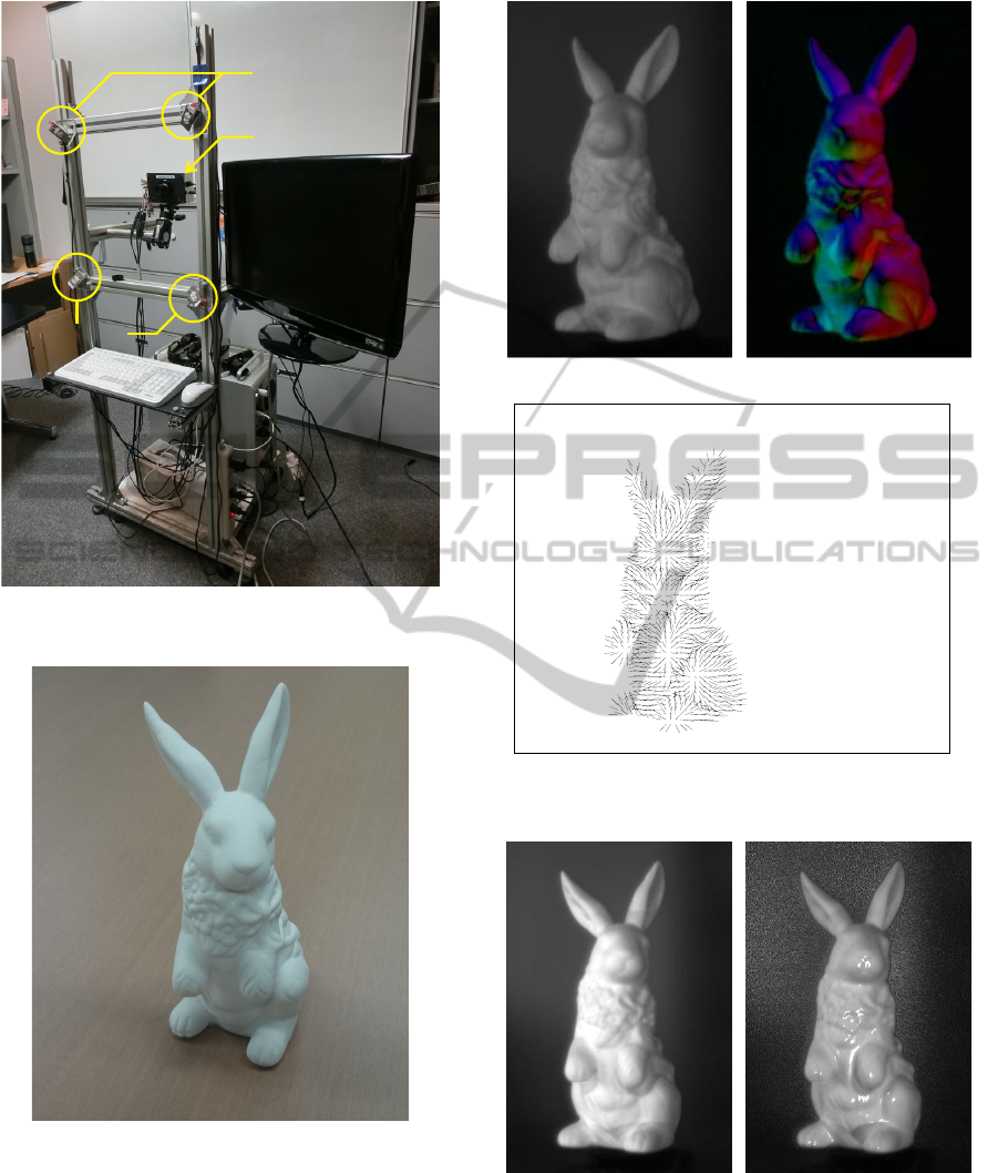
5 EXPERIMENTS AND RESULTS
In the first experiment, we confirm the ability of the
real-time surface orientation sensing. The target ob-
ject is paper clay rabbit shown in Fig.5, which has
diffuse reflectance property. Fig.6 shows captured im-
ages and reconstructed normal map.
Then we calculate reflectance transformation ac-
cording to Blinn model. Fig.7 shows reconstructed
intensity image for Blinn model m = 15. The rabbit in
the reconstructed image seems to be made of china or
to be covered somehow thin glass coating. So the ma-
terial perception is quite different from original rabbit
image.
In the next experiment, human face is used. Fig.8
shows captured images and reconstructed normal
map. Strictly speaking, reflectance property of the
VISAPP2015-InternationalConferenceonComputerVisionTheoryandApplications
242
Ir LED
Monitor
CIS
PC
Ir LED
LED
Power Supply
Figure 4: Photograph of real time surface orientation imag-
ing system.
Figure 5: Target object: paper clay rabbit.
human face is different from Lambert reflectance, but-
the reconstructed normal vector map shows its shape
well.
Fig.9 show reconstructed results for different
lighting conditions and reflectance parameters. These
result make an impression that human face is made of
china.
(a) Intensity image (b) Correlation image
(c) Needle map
Figure 6: Captured images and reconstructed normal map.
(a) (b)
Figure 7: Relighting results for artificial specular re-
flectance of Blinn model for m = 15. (a)original reflectance
property (diffuse), (b)Specular transformed object accord-
ing to Blinn model.
Real-timeMaterialTransformationusingSingleFrameSurfaceOrientationImager
243
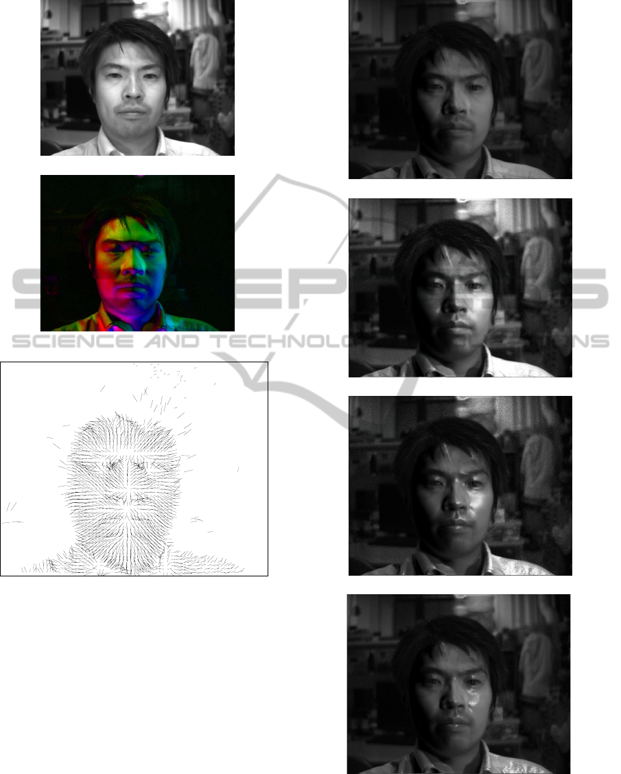
(a) Intensity image
(b) Correlation image
(c) Needle map
Figure 8: Captured images and reconstructed normal map.
6 CONCLUSIONS AND FUTURE
WORKS
We have developed real-time reflectance transforma-
tion system using four light sources and correlation
image sensor. Four light source and correlation image
sensor enables real-time disturbance illumination free
surface orientation imaging. Based on captured sur-
face normals, reflectance transformation images are
calculated and displayed on a monitor in real-time.
This technique shows possibilities for an image ex-
pressing method in a television broadcasting or other
(a) Diffuse
(b) m = 4
(c) m = 20
(d) m = 100
Figure 9: Relighting and reflectance transformation results.
(a)-(d)Reflectance parameters were changed in the same
lighting settings (θ, ϕ) = (26
◦
,0
◦
) .
VISAPP2015-InternationalConferenceonComputerVisionTheoryandApplications
244

media.
Based on the proposed system we will try further
development for other material perception. Further-
more, we will apply projection mapping technique to
transform material perception of real object. In other
words, we are trying real-time real world VFX.
REFERENCES
Ando, S. and Kimachi, A. (2003). Correlation im-
age sensor: Two-dimensional matched detection of
amplitude-modulated light. IEEE Trans. on Electron
Devices, 50(3):2059–2066.
Kurihara, T., Ono, N., and Ando, S. (2003). Surface orien-
tation imager using three-phase amplitude-modulated
illumination and correlation image sensor. In Pro-
ceedings of the SPIE, volume 5013, pages 95–102.
KURIHARA, T., ONO, N., and ANDO, S. (2012). Single-
frame surface orientation imager using triangular
three-phase amplitude-modulated illuminations and
correlation image sensor. Transactions of the Society
of Instrument and Control Engineers, 48(8):505–513.
Kurihara, T., Shimizu, T., Ono, N., and Ando, S. (2005).
Surface orientation imager with excluding capability
of non-lambertian reflectance. In Proceedings of the
SPIE, volume 5665, pages 9–16.
Malzbender, T., Wilburn, B., Gelb, D., and Ambrisco, B.
(2006). Surface enhancement using real-time pho-
tometric stereo and reflectance transformation. In
Proceedings of the 17th Eurographics Conference on
Rendering Techniques, EGSR ’06, pages 245–250,
Aire-la-Ville, Switzerland, Switzerland. Eurographics
Association.
Wenger, A., Gardner, A., Tchou, C., Unger, J., Hawkins,
T., and Debevec, P. (2005). Performance relighting
and reflectance transformation with time-multiplexed
illumination. ACM Trans. Graph., 24(3):756–764.
Real-timeMaterialTransformationusingSingleFrameSurfaceOrientationImager
245
