
Design of Tangible Procedural Programming of Robots
Based on Augmented Reality
Satoshi Matsuzaki
1
, Munehiro Takimoto
1
and Yasushi Kambayashi
2
1
Department of Information Sciences, Tokyo University of Science, Chiba, Japan
2
Department of Computer and Information Engineering, Nippon Institute of Technology, Saitama, Japan
Keywords:
Tangible, Augmented Reality, Programming, Robots.
Abstract:
This paper presents a tool for children aged 5 to 11 to learn procedural programming through tiling tangible
cards. In our tool, children are expected to tile square cards that respectively correspond to the unique oper-
ations of a robot while looking at them through a display, where the cards on the display are augmented by
intuitive colorful images. Once each image is augmented, the image stays on the display even if the corre-
sponding card is taken away. Also, the control flow from a card to another card is represented by a line image,
which is created when one places a card close to another card. In our tool, editing operations such as undo,
erase, and setting arguments can be also performed through movements of a special card. For feasibility study,
we have had one hundred students of primary schools use our tool. As a result, they learned programming
more quickly than programming in an existing tool where programs are composed through tiling icons.
1 INTRODUCTION
In these days, as Information and Communication
Technologies(ICT) is being developed, digital devices
or digital educational contents have been getting pop-
ular in primary schools or junior high-schools. In fact,
it is noticed that learning traditional subjects through
ICT enhances the understanding of them. Thus, it
is important for us to use ICT-based tools in the ed-
ucation. On the other hand, it is also important to
know how to take advantage of ICT to be ready for
further development of digital devices. One of the
most important purposes of the ICT education is to
understand the behaviors of software, which can be
directly learned through programming. It is, however,
not easy for children to learn programming in proce-
dural programming languages, which are used for im-
plementing most product-level software. One of the
reasons why children had hard time to learn procedu-
ral programming languages is that they are unfamiliar
with not only programming manner in the procedural
programming language, but also input devices such as
a keyboard and a mouse as well as software tools for
editing a program.
We propose a tangible programming environment
where the user composes a program through tiling
physical square cards. In our programming environ-
ment, each card is augmented by a special image cor-
responding to its own operation, which users can see
through a display. Once the image appears on a card,
it stays at the same location on the display even if the
card is taken away. The control flow between the op-
erations correspondingto the cards is also represented
as a line image connecting their images, which appear
when one places a card close to another card. That
is, the images on our environment entirely represent
a structure similar to a flow chart. We use a special
card, which we call adjustment card, for editing the
program. It is also augmented by a special image,
which is connected with the target card to edit by a
line image such as operation cards.The kind of edit-
ing is automatically selected depending on the con-
text, i.e. the kind of a target card.
The structure of the balance of this paper is as fol-
lows. In the second section we present a brief sketch
of our system and describe the kinds of cards used
by our system. The third section describes the pro-
gramming manner on our programming environment
through examples. In the fourth section, we show re-
lated works and describe the relations of our environ-
ment with them. Finally, we conclude our discussion
in the fifth section.
492
Matsuzaki S., Takimoto M. and Kambayashi Y..
Design of Tangible Procedural Programming of Robots Based on Augmented Reality.
DOI: 10.5220/0005358204920497
In Proceedings of the 10th International Conference on Computer Graphics Theory and Applications (GRAPP-2015), pages 492-497
ISBN: 978-989-758-087-1
Copyright
c
2015 SCITEPRESS (Science and Technology Publications, Lda.)
2 BACKGROUND
A lot of programming environments for beginners
of the programming or children have been proposed.
They are roughly categorized into graphical environ-
ments and tangible environments. One of the pop-
ular graphical environments is Scratch developed at
MIT (Resnick et al., 2009). In Scratch, users pro-
gram the behaviors of images by tiling block icons
with various shapes in the vertical direction on the
display, where the icons are arranged with a mouse.
IconWorks, which is similar to the Scratch, allows
users to program the behaviors of physical robots by
tiling square instruction icons in the horizontal direc-
tion (IconWorks, 2007). Both of them do not require
any description of programs code, so that it is easy for
children to understand the manner of programming or
to make a program.
Yashiro et al. extended the instruction blocks of
the Scratch to physical blocks, designing a tangible
interface where users can program the behaviors of
physical robots by composing the blocks by hands
as well as the behaviors of the images of robots on
a display (Yashiro and Kazushi, 2014). Even apart
from this, there are a lot of tangible interfaces using
the instruction blocks as a special device for program-
ming (Chawla et al., 2013; Smith, 2007; Smith, 2009;
Wang et al., 2012; Wang et al., 2013).
Horn et al. proposed a tangible interface where
users can program the behaviors of a robot by con-
necting puzzle pieces with pictures corresponding to
instructions by hands (Horn et al., 2008). Then, they
conducted experiments for comparing their environ-
ments with other graphical environments. They found
that the tangible environment is more attractive for
children, the girls of which strongly showed the ten-
dency. Also, the results showed that it was difficult
to make huge programs in the tangible environment
(Horn et al., 2009).
Fujita et al. proposed an environment where users
can program the behaviors of a robot through physi-
cally moving the robot by hand, where the movements
are recorded by tracing (Fujita et al., 2014). Also,
they conducted experiments for comparing their ap-
proach with a programming technique with a virtual
robot in terms of ease of understanding or imaging
the behaviors. As a result, they showed that the there
was no difference for effectiveness of the two envi-
ronments.
In comparison with these approaches, our envi-
ronments have effectively succeeded in composing
a graphical representation of programs with a tangi-
ble environment through the augmented reality tech-
nique. In addition, unlike most tangible techniques,
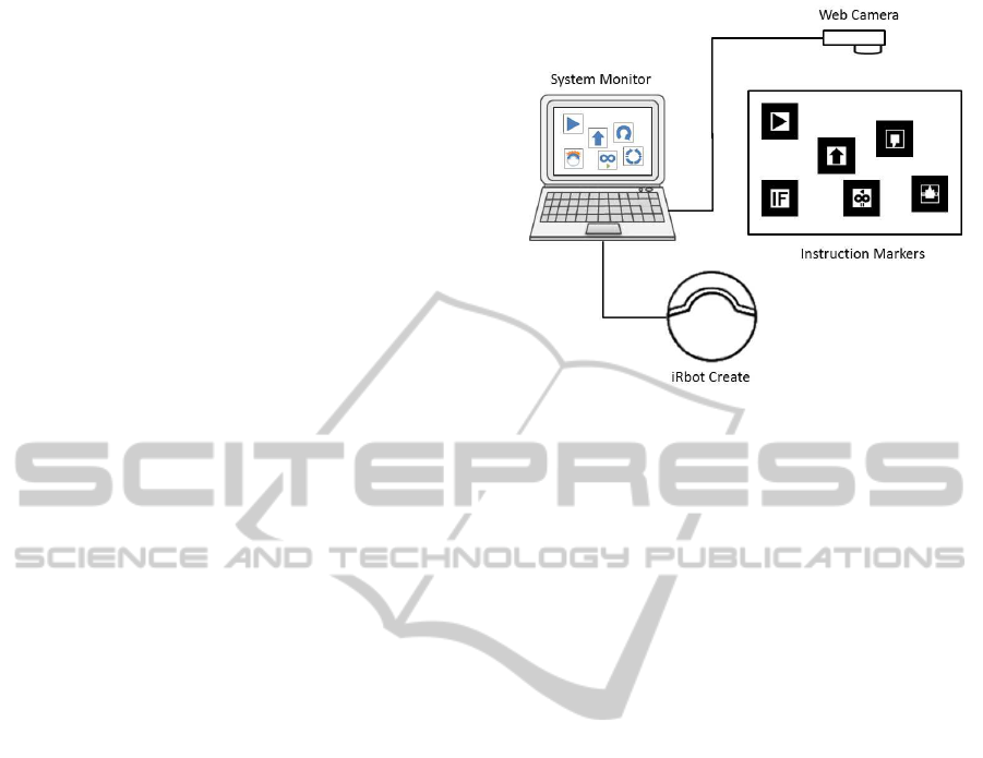
Figure 1: The overview of our system.
our approach does not require any special devices.
Further developments of such hybrid programming
environments could open a new horizon of the ICT
education.
3 PROGRAMMING
ENVIRONMENT
Fig. 1 shows the overview of the program environ-
ment that we have implemented. In our environment,
users compose a program by putting or moving square
cards by hand within the region specified by another
card to be connected with it. The card given by the
user is recognized as a marker for an overlaid image
through a web camera, which is sent to our system to-
gether with its geometry information and inclined de-
gree. Based on the information, our system overlays a
special image on each card so as to promote intuitive
understandings. The user tangibly composes a pro-
gram using the cards while seeing the overlaid images
on the display. We have implemented our prototype
system as a programming environment for controlling
a robot, where operations correspond to behaviors of
the robot. Therefore, the composed program is trans-
formed into a sequence of instructions to control the
robot, which is finally sent to the robot one by one.
3.1 Programming Cards
In our approach, programming consists of placing
physical operation card on a table. An operation
card is a 60mm × 60mm square sheet, on which a
40mm × 40mm monotone symbol is drawn as shown
in Fig.2(a). Once these symbols are recognized by
our system, color images are overlaid with the same
DesignofTangibleProceduralProgrammingofRobotsBasedonAugmentedReality
493
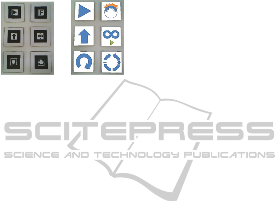
(a) Physical cards (b) Overlaid images
Figure 2: Programming cards.
size and at the same location on the display. The over-
laid images that correspond to the physical cards are
shown in Fig.2(b). The programming cards consist
of five operation cards and an adjustment card as fol-
lows:
• Start Card
represents the start point of a program, which is
the basis of arranging other cards as shown in the
top in the left column of Fig. 2 (a). The top in the
left column of Fig. 2(b) shows the image overlaid
on the start card.
• Move Card
is an operation card moving the robot forward
when it is arranged in the direction to the top, and
backward when it is arranged in the direction to
the bottom as shown in the middle in the left col-
umn of Fig. 2 (a) . The middle in the left column
of Fig. 2(b) shows the image overlaid on the move
card.
• Rotate Card
is an operation card rotating the robot to the right
direction as shown in the bottom in the left col-
umn of Fig. 2 (a). The bottom in the left column
of Fig. 2(b) shows the image overlaid on the rotate
card.
• Branch Card
is an operation card selecting a successive opera-
tion depending on whether the robot collides with
obstacles as shown in the top in the right column
of Fig. 2 (a). The top in the right column of Fig.
2(b) shows the image overlaid on the branch card.
• Iterate Card
is an operation card iterating the same operations
in the specific or arbitrary number of times as
shown in the middle in the right column of Fig.
2 (a). The middle in the right column of Fig. 2(b)
shows the image overlaid on the iterate card.
• Adjustment Card
is an adjustment card for adjusting a parameter
such as the distance of moving or the degree of
rotating, or undoing or redoing in editing the pro-
gram as shown in the bottom in the right column
of Fig. 2 (a). The bottom in the right column of
Fig. 2(b) shows the image overlaid on the adjust-
ment card.
4 PROGRAMMING MANNERS
In this section, we show how a program is composed
in our programming environment. The process of the
programming consists of placing the cards on a table.
The system recognizes the placed cards with a web
camera.
4.1 Setting up Cards
The programming in our system is performed by con-
structing virtual flow-chart by placing cards under a
web camera. We call the process of placing cards and
their recognition by the system through camera set-
ting up. Before being set up, most cards augmented
with gray frames as shown in Fig.3(a), which are
changed into blue one after the setting up. The frame
of the start card is initially blue because it has been
already set up as the basis of the arrangements. The
following cards are arranged to the relative locations
of the start card one by one. For example, consider
the process of setting up a move card. First, arrange
a move card in the right side of the start card so that
the move card is recognized as a candidate for setting
up by the system. The fact that the system has recog-
nized the new card as a next candidate is represented
by the red frame and the red line connecting with the
existing card as shown in Fig.3(b). If several cards are
put in the right side of the existing card, the card clos-
est to the existing card is chosen as a next candidate
to be set up.
In order to set it up as one of instructions in the
program, the candidate card has to be held for three
seconds. The fact that the move card is successfully
set up is represented by the change of the color of the
line connecting with the start card. It is changed from
red to green as shown in Fig.3(c). When we want to
set a parameter with the card such as the move card,
the parameter has to be adjusted. In our example, the
move card has a parameter for the distance to move.
We will describe the adjustment cards in Section 4.4.
Once the move card is set up, another card can be
arrangedto be set up in the right side of the movecard.
Thus, as far as the cards are within the view rageof the
GRAPP2015-InternationalConferenceonComputerGraphicsTheoryandApplications
494
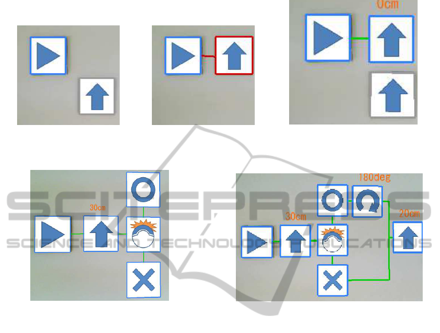
(a) Initial state (b) Recognizing a move card (c) Setting up the move card
Figure 3: The process of setting up a move card.
Figure 4: Setting up a branch card.
web camera, new cards can be set up. In other words,
as long as the start card is within the view range, any
cards can be drawn by the information of the distance
relative to the start card, which is recorded in setting it
up. Because of that, the images overlaid on the cards
can be continuously drawn, even if the cards are taken
away, so that we can reuse the same card over and
over. We do not need to have arbitrary number of the
same cards. In fact, we provide only one card for each
kind of instructions.
4.2 Handling Branches
Conditional branch is an essential part of procedu-
ral programming. Using branch cards, we can se-
lect successive operations to be executed depending
on whether the robot has collided or not. The colli-
sion detection is performed from the starting point of
the previous operation to the starting point of branch
operation. Fig. 4 shows images immediately after the
branch card is set up following move in 30cm. Once
the branch card is set up, circle and cross images ap-
pear above and below the branch card, respectively.
If a user wants to execute some operations when the
result of the collision detection is true, they have to
Figure 5: Merging control flows.
be set up in the right side of the circle; otherwise,
they have to be set up in the right side of the cross.
Also, the branched operations are merged by putting
any card between two branched sequences of opera-
tions, which is not necessary. A branch does not al-
ways have to be merged.
Fig. 5 shows that the robot moves in 30cm, and
then, if it collides with any obstacles, it rotates in
180 degrees, and then it further moves in 20cm. As
in many popular programming languages, the branch
operations can be nested, but branched operations
have to be merged in inner most operations first.
4.3 Handling Iterations
Using iterate cards, we can iterate operations in the
specific or arbitrary number of times. The iterate card
represents the entry of iterations, and rotating it in 180
degrees, it represents the exit of the iterations. That is,
operations surrounded by the two iterate cards repre-
sent a loop. Fig. 6 shows that moving in 30 cm is
iterated five times.
DesignofTangibleProceduralProgrammingofRobotsBasedonAugmentedReality
495
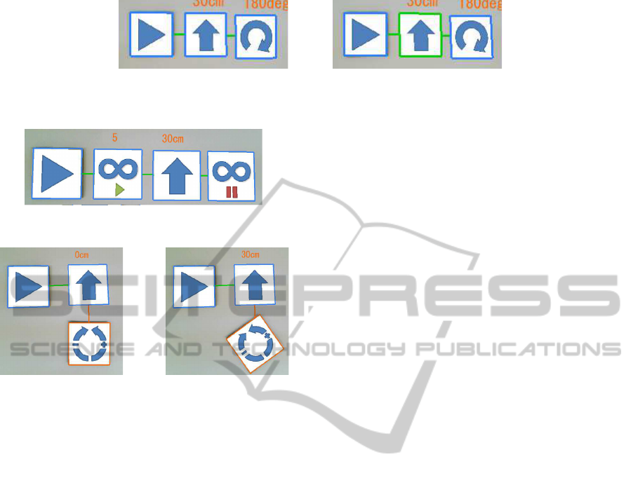
(a) Before execution (b) Under execution
Figure 8: Emphasizing an executed image.
Figure 6: Iterative operations.
(a) Connecting the adjustment
card with a target
(b) Modifying a parameter by ro-
tating the adjustment card
Figure 7: Setting the value of a parameter.
4.4 Editing by Adjustment Cards
The adjustment cards can be used for setting the value
of a parameter and editing operations, undo and redo.
In our system, the operations with a parameter are the
move operation, the rotate operation, and the branch
operation. When a user wants to modify the param-
eter of a card, he or she places the adjustment card
below the card. Fig.7(a) shows a situation that the ad-
justment card is placed to be connected with a move
card. After placing the card, the user rotates the ad-
justment card in a clock-wise direction, so that the
value of the parameter increases depending on the ro-
tation degree as shown in Fig.7(b).
On the other hand, in order to use the adjustment
card for editing, users put it below the start card. Once
the adjustment card is connected with the start card,
each operation is undone a rotation in 10 degrees in
a clock-wise direction in placed order. Also, rotating
it in 10 degrees in a counter-clock-wise direction, the
undone operation can be restored.
4.5 Execution
When the program is completed, the user can execute
the program by pushing the enter key. The execu-
tion starts from the start image, and continues along
the control flow represented by the lines connecting
the overlaid images. In the process of the execution,
the operation image currently executed is augmented
by a green frame. For example, when executing the
program as shown in Fig.8(a), Fig.8(b) shows that the
move operation corresponding to a move card image
is currently executed. The highlighting current oper-
ation is useful for debugging the program as well as
helping the user understand the behaviors of his or her
program.
5 CONCLUSIONS AND FUTURE
WORKS
This paper presents an integrated development envi-
ronment for programming intuitively by using square
cards as an interface. We implemented a prototype of
our system, and had one hundred students of primary
schools use the system in the open campus or vising
laboratories. From the observation of the students,
we found that they could understand the program-
ming manner more efficiently than the similar pro-
gramming environment, icon works, which was op-
erated with a mouse. Also, some of them reached the
level where they made some new programs compos-
ing several operations by themselves. Even students
that were initially making only given programs began
making new programs by giving them some subjects
regarding specific behaviors.
In our system, users adjust the parameters of the
operation cards, or edit the images overlaid on the op-
eration cards by rotating the adjustment card, which
has to be recognized through the a web camera over
the table. At this time, once the hand used to hold a
card hides the symbol described on the card, it cannot
be recognized, so that programming cannot be con-
tinued. We can solve this problem through scaling
down the size of the symbol, or using the card whose
four corners have the different sub-symbols, which
are called multiple markers. Also, in our system, the
programming area is restricted within the view range
of the web camera. The fact means that it is hard to
represent long or complex programs. In order to miti-
gate this problem, we are introducing modules to our
GRAPP2015-InternationalConferenceonComputerGraphicsTheoryandApplications
496

system. For example, once some images are specified
as a module, they are represented by the image cor-
responding to an operation card. The modularization
condenses several images into a single image so that
the complex program composed of several images is
simplified.
We are aware of the needs of improvement of our
editing manner. In our system, the specific image can-
not be selected for remove or overwrite. Because the
only operation allowed as remove is just undo, which
removes images in the newest first.
In addition to these improvements, it is required to
apply our system to more wide audiences, and to so-
phisticatedly analyze the experimental results to show
the effectiveness of our system.
ACKNOWLEDGEMENTS
This work is supported in part by Japan Society for
Promotion of Science (JSPS), with the basic research
program (C) (No. 26350456), Grant-in-Aid for Sci-
entific Research.
REFERENCES
Chawla, K., Chiou, M., Sandes, A., and Blikstein, P. (2013).
Dr. wagon: a ’stretchable’ toolkit for tangible com-
puter programming. In Interaction Design and Chil-
dren 2013, IDC ’13, New York, NY, USA - June 24 -
27, 2013, pages 561–564. ACM.
Fujita, T., Mi, H., and Sugimoto, M. (2014). An intuitive
programming technique using tangible robotson table-
top environments. In IPSJ Interaction 2011.
Horn, M. S., Solovey, E. T., Crouser, R. J., and Jacob, R.
J. K. (2009). Comparing the use of tangible and graph-
ical programming languages for informal science ed-
ucation. In Proceedings of the 27th International
Conference on Human Factors in Computing Systems,
CHI 2009, Boston, MA, USA, April 4-9, 2009, pages
975–984. ACM.
Horn, M. S., Solovey, E. T., and Jacob, R. J. K. (2008).
Tangible programming and informal science learning:
making tuis work for museums. In Proceedings of
the 7th International Conference on Interaction De-
sign and Children, IDC 2008, Chicago, Illinois, USA,
June 11-13, 2008, pages 194–201. ACM.
IconWorks (2007). EK Japan Co., ltd.,
http://www.elekit.co.jp/download/software/00007.
Resnick, M., Maloney, J., Monroy-Hern´andez, A., Rusk,
N., Eastmond, E., Brennan, K., Millner, A., Rosen-
baum, E., Silver, J. S., Silverman, B., and Kafai, Y. B.
(2009). Scratch: programming for all. Commun.
ACM, 52(11):60–67.
Smith, A. C. (2007). Using magnets in physical blocks that
behave as programming objects. In Proceedings of the
1st International Conference on Tangible and Embed-
ded Interaction 2007, Baton Rouge, Louisiana, USA,
February 15-17, 2007, pages 147–150. ACM.
Smith, A. C. (2009). Symbols for children’s tangible pro-
gramming cubes:an explorative study. In SACLA ’09,
29 June - 1 July, Mpekweni Beach Resort, South
Africa.
Wang, D., Qi, Y., Zhang, Y., and Wang, T. (2013). Tanpro-
kit: a tangible programming tool for children. In In-
teraction Design and Children 2013, IDC ’13, New
York, NY, USA - June 24 - 27, 2013, pages 344–347.
ACM.
Wang, D., Zhang, Y., Gu, T., He, L., and Wang, H. (2012).
E-block: a tangible programming tool for children. In
The 25th Annual ACM Symposium on User Interface
Software and Technology, UIST ’12, Cambridge, MA,
USA, October 7-10, 2012 - Adjunct Volume, pages 71–
72. ACM.
Yashiro, T. and Kazushi, M. (2014). Material program-
ming – a visual programming development environ-
ment with material –. In IPSJ Interaction 2014.
DesignofTangibleProceduralProgrammingofRobotsBasedonAugmentedReality
497
