How to Choose the Best Embedded Processing Platform for on-Board
UAV Image Processing ?
Dries Hulens
1
, Jon Verbeke
2
and Toon Goedem
´
e
1
1
EAVISE, KU Leuven, Sint-Katelijne-Waver, Belgium
2
Propolis, KU Leuven, Oostende, Belgium
Keywords:
UAV, Vision, on-Board, Real-time, Speed Estimation, Power Estimation, Flight Time Estimation.
Abstract:
For a variety of tasks, complex image processing algorithms are a necessity to make UAVs more autonomous.
Often, the processing of images of the on-board camera is performed on a ground station, which severely
limits the operating range of the UAV. Often, offline processing is used since it is difficult to find a suitable
hardware platform to run a specific vision algorithm on-board the UAV. First of all, it is very hard to find a
good trade-off between speed, power consumption and weight of a specific hardware platform and secondly,
due to the variety of hardware platforms, it is difficult to find a suitable hardware platform and to estimate
the speed the user’s algorithm will run on that hardware platform. In this paper we tackle those problems by
presenting a framework that automatically determines the most-suited hardware platform for each arbitrary
complex vision algorithm. Additionally, our framework estimates the speed, power consumption and flight
time of this algorithm for a variety of hardware platforms on a specific UAV. We demonstrate this methodology
on two real-life cases and give an overview of the present top processing CPU-based platforms for on-board
UAV image processing.
1 INTRODUCTION
Nowadays UAVs (Unmanned Aerial Vehicles) are
used in a variety of tasks such as surveillance, in-
spection, land surveying,. . . They are mostly manually
controlled remotely or follow a predefined flight path,
while collecting interesting images of the environ-
ment. These images are often analyzed offline since
the processing power of these UAVs is limited. Other-
wise a wireless link is provided to do the processing of
the images on a ground station giving the instructions
to the UAV. To be more autonomous and operate more
robustly, UAVs should be equipped with processing
power so that images can be processed on-board. This
will ensure that UAVs can analyze and react in real-
time on the images and that they can fly much fur-
ther since a wireless link is not necessary. Recent
advances concerning embedded platforms show an
ongoing increase in processing power at reasonable
power consumption and weight. Currently, it even
becomes possible to employ these complex hardware
platforms under UAVs. However, since various pa-
rameters need to be taken into account, finding an op-
timal hardware platform for a specific algorithm is not
trivial.
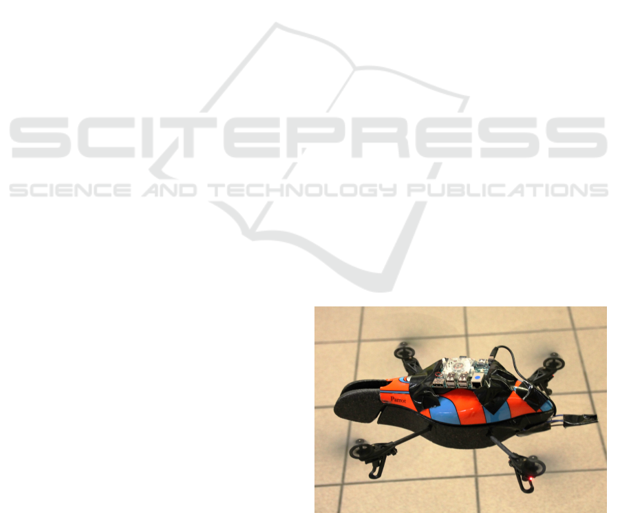
Figure 1: Parrot AR Drone carrying an Odroid hardware
platform for real-time vision processing.
Example applications that need on-board complex
image processing are e.g. visual SLAM for 3D sense
and avoid, the detection and tracking of people for
surveillance purposes, navigating through the corri-
dor between trees in an orchard for counting fruit, the
automation of a film crew by UAVs, a vision-based
navigation system to automatically clean solar pan-
els,. . . Determining the optimal trade-off between the
processing capabilities and the physical constraints is
377
Hulens D., Verbeke J. and Goedemé T..
How to Choose the Best Embedded Processing Platform for on-Board UAV Image Processing ?.
DOI: 10.5220/0005359403770386
In Proceedings of the 10th International Conference on Computer Vision Theory and Applications (VISAPP-2015), pages 377-386
ISBN: 978-989-758-091-8
Copyright
c
2015 SCITEPRESS (Science and Technology Publications, Lda.)

a daunting task because of their variety. Therefore, in
this paper we answer the question: Which hardware
platform is best suited to perform a particular image
processing task on a UAV? A hardware platform can
be a simple embedded processor (e.g. a Raspberry PI)
or even a small computer like a laptop, depending on
the processing power that is needed. Using these un-
der a UAV impose severe constraints on the hardware
platforms: they should be lightweight, small and have
adequate processing power at low power consumption
to maintain long flight times. To determine the ef-
fective processing speed of a particular algorithm on
a specific hardware platform, one should implement
the algorithm on each specific platform. Acquiring a
large variety of test platforms to determine the most
suitable one evidently is not time nor cost efficient.
Therefore, in this paper we present a framework that,
given a specific algorithm, estimates the processing
speed, power consumption and flight time on a large
set of hardware platforms, without the need to acquire
any of them. For this we rely on two benchmark algo-
rithms. This paper provides data for a number of hard-
ware platforms only restricted in the fact that they are
CPU-based. However since our framework is generic,
new platforms can easily be added to the framework.
An overview of the platforms that we have included
can be found in Table 1.
The framework will be evaluated on two real
cases. In the first case we track a person with a UAV
using a face detection algorithm (Viola and Jones,
2001). For this, we search for a hardware platform
that can run the face detector at 4fps while minimizing
the power consumption (e.g. maximum flight time).
In our second case the UAV should visually navigate
through a fruit orchard corridor, running a vantage
point detection algorithm (Hulens and Vanderstegen,
2012) on-board at 10fps.
The main contributions of this paper are:
• State-of-the-art overview of the current best CPU-
based processing platforms for complex image
processing on-board a UAV.
• Present experimental results of benchmark com-
puter vision experiments on each of these state-
of-the-art platforms.
• We propose a generic model to estimate the pro-
cessing speed, power consumption and UAV flight
time of any given image processing algorithm on
a variety of hardware platforms.
• Validation of the proposed generic model on two
real cases (people detection/tracking and vision-
based navigation).
This paper is structured as follows: in the next sec-
tion we give an overview of the related work on this
topic. In section 3 we briefly discuss the hardware
platforms that we used in the framework. In section 4
we present our framework and in section 5 we verify
our framework with some experiments and show our
results.
2 RELATED WORK
Currently, UAVs are often used to capture images of
the environment which are then processed afterwards
e.g. surveying (Siebert and Teizer, 2014). For this the
UAVs are controlled manually or by means of GPS.
However, our main focus is on autonomously flying
UAVs. To enable this, UAVs mainly rely on vision al-
gorithms. Therefore, algorithms like path planning
and obstacle avoidance (e.g. object detection) are
used to steer the UAV to a certain position (Suzuki
et al., 2011; Ferrick et al., 2012; Lin and Saripalli,
2014). Due to their computational complexity, on-
board UAV processing is often practically unfeasible.
Therefore, in these approaches, a ground station (with
desktop computer) is used to process the images and
steer the UAV. However this severely limits their op-
erating range.
In cases where on-board processing currently is
employed, only light-weight algorithms are used. For
example (McGee et al., 2005) use sky segmentation
(color segmentation), running on a Pentium III pro-
cessor, to detect and avoid objects in the sky. (Meier
et al., 2011) use a marker detection system to follow
a predefined path.(Sa et al., 2014) use line detection,
running on a Cortex-A9, for the inspection of pole-
like structures. (Wenzel et al., 2011) track an IR-
LED-pattern mounted on a moving platform, using a
ATmega 644P controller and (Anthony et al., 2014)
filters laser scanner data on an Atom-based process-
ing platform to estimate crop height.
However, our real-life test case algorithms are
much more complex. To implement more complex
algorithms on a UAV often FPGAs or ASICs are used
since they offer an optimal trade-off between weight,
power consumption and processing power. (Kok
et al., 2013) designed an FPGA based path planning
algorithm, and (Ehsan and McDonald-Maier, 2009)
evaluate other hardware like ASICs as on-board vi-
sion processing platform.
However, translating e.g. OpenCV code (C, C++
or python) to hardware (using e.g. VHDL) is a te-
dious and time consuming task. (Nieuwenhuisen and
Behnke, 2014) use a high-end processing platform for
on-board path planning and obstacle avoidance. This
is possible since, in their case, power consumption or
weight is less relevant because they use an octacopter
VISAPP2015-InternationalConferenceonComputerVisionTheoryandApplications
378
Table 1: Overview hardware platforms that we have tested for our framework.
Name Processor Memory Weight
(gram)
Power@100%
(Watt)
Volume (cm
3
)
Desktop Intel I7-3770 20GB 740 107 4500
Raspberry PI model B ARM1176JZF-S 512MB 69 3,6 95
Odroid U3 Samsung Exynos4412 2GB 52 6,7 79
Odroid XU3 Samsung Exynos 5422 2GB 70 11 131
Jetson Cortex A15 2GB 185 12,5 573
mini-ITX atom Intel Atom D2500 8GB 427 23,5 1270
mini-ITX intel I7 Intel I7-4770S 16GB 684 68 1815
Nuc Intel I5-4250U 8GB 550 20,1 661
Brix Intel I7-4500 8GB 172 26 261
with a large carrying capacity.
Currently, work exists which achieves real-time
performance of complex vision algorithms on UAV
mounted embedded platforms (Shen et al., 2013;
De Wagter et al., 2014; Forster et al., 2014). How-
ever, their algorithms are specifically adapted or de-
signed to perform real-time performance on a targeted
hardware platform. We aim to develop a framework
that performs the opposite operation; i.e. given a spe-
cific algorithm we determine the most suited hard-
ware platform.
To resolve all problems mentioned above, in this
paper we present a framework that automatically de-
termines the most suitable hardware platform given
a user’s computer vision algorithm from state-of-the-
art, affordable (from $30 to $800), embedded plat-
forms. Our framework enables the use of complex
computer vision algorithms which run in real-time on-
board of the UAV, directly programmed in OpenCV.
3 STATE-OF-THE-ART IMAGE
PROCESSING PLATFORMS
Nowadays, a number of CPU-based processing plat-
forms are available which are lightweight and pow-
erful and therefore suited for the task at hand. An
overview is given in Table 1.We will describe them
briefly, in order of ascending processing power (and
thus increasing weight).
A well-known lightweight processing platform is
the Raspberry PI. The PI is a small, low-cost 1GHz
ARM11 based hardware platform developed for edu-
cational purposes. The main advantage of this small
platform is that it runs a linux-based distribution,
which allows the compilation and usage of well-
known vision libraries e.g. OpenCV. Of course, the
processing speed is limited, but simple vision algo-
rithms, like e.g. face detection based on skin color
segmentation, run at real-time performance. The PI is
equipped with a Broadcom GPU which recently be-
came open-source.
A more powerful alternative for the PI is the fam-
ily of Odroid platforms. One of those platforms is
the U3 that is even smaller than the PI and has an
ARM based 1.7GHz Quad-Core Samsung processor
that is also used in smartphones. Speed tests on the
U3 indicated that this platform is 20 times faster than
the Raspberry PI. The XU3 is another Odroid plat-
form which has a Samsung Exynos5422 Cortex-A15
2.0GHz quad core and a Cortex-A7 quad core pro-
cessor making him two times faster as the U3. The
XU3 has a fan to cool the processor where the U3 is
passively cooled. Both the U3 and XU3 are equipped
with an eMMC slot which is a much faster alternative
for the SD card.
Another novel and promising platform is the Jet-
son TK1 Development Kit with an on-board NVIDIA
GPU and a quad-core ARM15 CPU, making the plat-
form especially useful for GPU based vision algo-
rithms. In this paper we only perform experiments on
the CPU but in future work the GPU will also be eval-
uated. The Jetson has several IO ports making it easy
to communicate with sensors or inertial measurement
units (IMUs), it even has a sata connection for a hard-
drive. The CPU speed is comparable with the U3, but
when GPU vision algorithms are used this platforms
really shines.
A more powerful family of hardware platforms are
the Mini-ITX platforms. Mini-ITX platforms all have
the same dimensions (17×17cm) but can be equipped
with different processors and IO. They are basically
small computers with the same IO as a normal desk-
top computer. The mini-ITX platforms can be classi-
fied into two categories: the Atom platforms that can
be compared with netbooks and the I7-3000 platforms
that can be compared with desktops. The Atom Mini-
ITX platform has a 1.86GHz Fanless Dual Core pro-
cessor like in many netbooks computers. Its speed is
comparable with the U3 and therefore less interesting
due to its larger size, power consumption and weight.
Unlike the previous, the Intel i7-3770 platform has a
quad core processor and is much faster. This platform
is one of the fastest platforms we have tested in this
HowtoChoosetheBestEmbeddedProcessingPlatformforon-BoardUAVImageProcessing?
379
paper. It is five times faster than the XU3 and even
faster than our reference system that we used (normal
desktop computer). Together with a power supply that
can be connected to a LiPo battery and a SSD hard
drive, this platform can handle complex image pro-
cessing algorithms on-board a UAV. The disadvantage
of this platform is its power consumption and weight.
The next family of platforms are the Brix and Nuc
barebone mini-computers. These computers are de-
signed to be mounted on the back of a monitor and
have a size of 11 × 11cm. These platforms consume
less power than the Mini-ITX I7 platform but are
twice as slow, which is still very fast for such a small
computer. The Brix has an Intel I7-4500 quad-core
processor and is comparable in speed with the Nuc
that has an Intel I5-4250U processor. When stripping
down the casing of these two platforms, the Brix only
weighs 172g (SSD included) compared to the Nuc
that still weigh 550g, giving the Brix the most inter-
esting specs to mount on a UAV for complex image
processing algorithms. Section 5.1 gives an overview
of the tests we have performed on these platforms.
4 APPROACH
The goal of our framework is to find the best hard-
ware platform to run a user’s new vision algorithm on
a UAV. The main criterion we try to optimize is the
amount the processing platform reduces the UAV’s
flight time. Indeed, both because of the hardware plat-
form’s own weight and of its electrical power con-
sumption it drains the battery during flight.
The best platform is found when a vision algo-
rithm can run on it at a certain required speed (in fps
frames per second), while it consumes as little as pos-
sible and the weight of the platform is as low as possi-
ble in order to extend flight time. The required speed
can be much lower than the maximum speed that the
algorithm can run on a certain platform, e.g. a face de-
tector that runs at 100 fps but only 20 fps is required
for a certain application. The power consumption
reduces dramatically when reducing the frame rate
of the algorithm on the same platform. We propose
a generic calculation model that estimates the flight
time reduction for an arbitrary vision algorithm on a
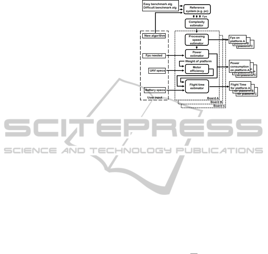
specific embedded processing platform. As seen in
Figure 2 this model consists of six blocks. In the first
block the user’s new algorithm and two benchmark al-
gorithms are executed on a reference system (e.g. the
user’s desktop computer) and their frame rate is given
to the next block where the relative complexity of the
new algorithm is estimated. With this, for each hard-
ware platform, its speed is estimated in the next block.
Figure 2: Overview of our framework.
Then the power consumption of every platform, while
running the new algorithm at a certain required speed,
is estimated. In the next block the power consump-
tion of the UAV carrying each hardware platform is
calculated. Finally, in the last block the flight-time of
the UAV, carrying each hardware platform running the
new algorithm at a certain speed, is estimated. In the
next subsections these blocks are discussed in detail.
4.1 Complexity and Processing Speed
Estimator
To estimate the speed of a new algorithm on every
hardware platform we first estimate the complexity
of this algorithm. For the sake of simplicity, we as-
sume a linear relation between the processing speed
and the complexity of the algorithm. We will validate
this linearity assumption in section 5. The speed of
the algorithm ( f
alg
=
1
T
alg
) on the reference system,
e.g. the user’s desktop PC, is used as measurement
for the complexity (C
alg
). We empirically measure
the relative complexity of the new algorithm with re-
spect to two reference (benchmark) algorithms. The
first benchmark algorithm is an easy algorithm that
we let correspond with 0% complexity (C
1
). For this
algorithm we chose the OpenCV implementation of a
3×3 median filter on a color image of 640×480 pix-
els. The second algorithm is a more difficult algo-
rithm that corresponds to a complexity of 100% (C
2
),
where OpenCV’s HOG person detector is applied to
an image of 640×426 pixels. Our Complexity estima-
tor uses the execution time of these two benchmark
algorithms (T
1
and T
2
) and the user’s new algorithm
(T
alg
) running on the reference system to calculate the
complexity of the new algorithm (see Figure 3). The
complexity is then calculated as:
VISAPP2015-InternationalConferenceonComputerVisionTheoryandApplications
380
Figure 3: Linear complexity model. Complexity C
alg
(red)
is estimated with T
1
, T
2
and T
alg
as input (green).
C
alg
=
T
alg
− T
1
T
2
− T
1
C
2
+C
1
(1)
We assume a linear relation between the compu-
tational complexity and the speed of these vision al-
gorithms because they all do mainly the same opera-
tions, like applying filters on an image and extracting
features. Vision algorithms are always data intensive
but most of the time not computationally intensive.
Note that code optimizations for specific architectures
evidently affect the results. Details like memory us-
age are not taken into account in this simple model,
because the memory on the advanced hardware plat-
forms is easy expandable. Moreover, in our model
we only assume CPU-based processing platforms, no
other architectures such as GPU or FPGA for which a
code translation step would be necessary. In section 5
the validity of this linear relation is verified.
Now that the complexity of the new algorithm
(C
alg
) is known, the speed of the algorithm can be es-
timated on every platform by following Figure 3 in
the other direction, as demonstrated in Figure 4 for
two fictitious platforms. The simple and difficult al-
gorithm is run on every platform what results in a T
1
and T
2
for each platform. Because C
alg
is known from
the previous step, T
alg
can now be calculated for each
platform:
T
alg
=
C
alg
−C
1
C
2
(T
2
− T
1
) + T
1
(2)
At this point the speed ( f
alg
=
1
T
alg
) of a new al-
gorithm can be estimated for each hardware platform,
hence in the next step we can estimate the power con-
sumption of the new algorithm on each platform.
4.2 Power Estimator
In UAV applications flight time is of utmost impor-
tance. Therefore our framework estimates the power
Figure 4: Calculating T
alg
(red) for each processing plat-
form (blue and orange) with known C
alg
, T 1 and T 2.
consumption of each hardware platform running the
new algorithm at the required speed. We performed
experiments to determine the relation between pro-
cessing speed and power consumption, indicating that
a linear model is again a good approximation (see
Section 5). When the maximum speed of the al-
gorithm is not required, the power consumption can
be lower than when the algorithm is running at full
speed. By taking the required fps as an input of the
Power Estimation Block we can estimate the power
consumption more precisely for each platform.
To calculate the power consumption P
alg
of a cer-
tain algorithm, the power consumption of each plat-
form is measured when in idle state P
idle
(doing noth-
ing) and when running all cores at full speed P
max
(algorithm running at full speed). Together with the
required speed (in frames per second) f
req
and the
maximum speed of the algorithm f
max
the power con-
sumption of the platform can be linearly interpolated
as follows:
P
alg
=
P
max
− P
idle
f
max
f
req
+ P
idle
(3)
In this step we also have to eliminate hardware
platforms which do not reach the required fps (when
1
T
alg
< f
req
). At this point the power consumption
of every remaining platform, running the user’s new
algorithm at a certain speed, is known. In the next step
the power consumption of the UAV itself, carrying the
platform as payload, is calculated.
4.3 Motor Efficiency
In (Verbeke et al., 2014) a model has been developed
that enables the user to estimate the power consump-
tion of a multicopter at hover. The performance esti-
HowtoChoosetheBestEmbeddedProcessingPlatformforon-BoardUAVImageProcessing?
381

mates are based on momentum disk theory and blade
element theory of helicopters combined with empir-
ically determined correction factors for multicopters
(Prouty, 1995). The model requires the user to in-
put several parameters such as weight, number of
propellers n
props
and propeller radius R. The model
uses some empirical parameters such as the Figure of
Merit FM (basically the propeller efficiency), the mo-
tor efficiency η
motor
(including the electronic speed
controller efficiency) and an installed-to-hover power
ratio
P
installed
P
hover
of 2 (based on industry standards). The
empirical parameters were determined with actual
tests on several motors and propellers which are mid-
dle grade RC components. The user can (slightly)
change these as their multicopter might have higher
or lower grade components. We will use this model
to estimate the power consumption of the UAV carry-
ing the hardware platform.
During hover and slow forward flight it can be
assumed that thrust T
hov
(approximately) equals the
total weight force W
tot
in Newton (W
tot
= m
tot
g =
(m
UAV
+ m
plat f orm
)g) and the hover power per pro-
peller can be calculated through the disk loading DL,
induced velocity v
i
and air density ρ:
DL =
W
tot
πR
2
n
props
(4)
P
hov
theo
= T
hov
v
i
hov
= W
tot
v
i
hov
= W
tot
s
DL
2ρ
(5)
P
hov
real
=
P
hov
theo
FMη
motor
(6)
Calculating the power consumption of the multicopter
based on hover conditions is a rather safe method as
during slow forward flight the required power actu-
ally decreases by 10% and most multicopter opera-
tions take place in this regime (Theys et al., 2014).
Together with the hardware power consumption
P
alg
, the total electrical power consumption P
tot
can
be calculated as:
P
tot
=
W
tot
q
DL
2ρ
FMη
motor
+ P
alg
(7)
At this stage the total power consumption of the UAV,
carrying the hardware platform that is running a cer-
tain algorithm, is known. In the next subsection the
flight time is estimated.
4.4 Flight Time Estimator
The flight time for every platform can be estimated
since the power consumption of every platform run-
ning an algorithm at a certain speed together with the
power consumption of the UAV itself carrying each
of the platforms is known now. These two values to-
gether with the capacity of the batteries are the inputs
of this block. Nowadays most UAVs are using lithium
polymer batteries because of their good capacity vs
weight ratio. Nevertheless the capacity mentioned on
the batteries applies only as long as the remaining bat-
tery voltage is above a certain value. Therefore most
of the time 75% of the battery’s capacity is taken as
a more fair value to calculate the flight time. Flight
time is subsequently calculated as follows:
T
f light
(h) =
0.75V
bat
C
bat
P
tot
(8)
where C
bat
is the capacity mentioned on the battery
in Ah, V
bat
is the voltage of the battery and P
tot
is the
total power consumption of the UAV at hover (eq. 7).
At this point the main question “Which hardware
platform is best suited to perform a particular image
processing task on a UAV?” can be answered, which
we will demonstrate in the next section for our two
example algorithms.
5 EXPERIMENTS AND RESULTS
We performed extensive experiments to validate our
framework using a wide variety of platforms and mul-
tiple algorithms. In the first subsection we performed
multiple speed tests of two algorithms to compare the
different hardware platforms. In the next subsection
we proof that the assumption of a linear complexity
and power model holds. Finally we present valida-
tion experiments on two computer vision-based real-
life cases: face detection and tracking on a UAV for
people following and visual navigation to find the cor-
ridor in an orchard for fruit counting/inspection.
5.1 Speed Tests of Two Algorithms on
each Hardware Platform
In our first test the processing speed of the OpenCV
implementation of a HOG person detector and a Viola
and Jones face detector is measured on all platforms.
Thereby speed can be compared for every hardware
platform. The result can be seen in Figure 5. In Figure
6 we display the ratio of the measured speed of these
two algorithms and the power consumption of every
platform while running the two algorithms. Figure 7
displays the ratio of the speed and the volume of the
hardware platforms and in Figure 8 the ratio of the
processing speed and the weight of the platforms is
shown.
As seen in Figures 5 - 8, the Mini ITX Intel I7
VISAPP2015-InternationalConferenceonComputerVisionTheoryandApplications
382
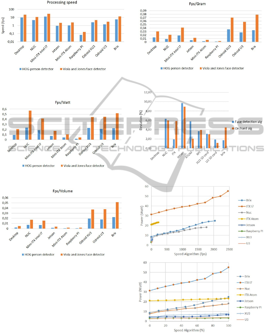
Figure 5: Speed (logarithmic) of HOG person detector
(blue) and Viola and Jones Face detector (orange) for ev-
ery platform.
Figure 6: Processing speed/ power consumption ratio for
every hardware platform.
Figure 7: Processing speed/ volume ratio for every hard-
ware platform.
platform is one of the fastest but also very heavy.
The Jetson and Atom platforms score below average
compared to the other platforms because the Jetson is
a processing platform designed for GPU implemen-
tations and the Atom is already an older generation
of CPUs. The Nuc and Brix have a similar speed
and power consumption, but the Brix is much lighter
and smaller. The two Odroid platforms are similar in
power consumption, volume and weight but the XU3
is twice as fast as the U3 platform. Overall, the Brix
scores best when all test are taken into account.
Figure 8: Processing speed/ gram ratio for every hardware
platform.
Figure 9: Deviation between estimated fps and measured
fps of our two real-case-algorithms.
Figure 10: Power consumption of each platform measured
while increasing the speed (top: in fps, bottom: in %) of the
easy (Median filter) algorithm.
HowtoChoosetheBestEmbeddedProcessingPlatformforon-BoardUAVImageProcessing?
383
Table 3: Results of our framework for the face detection and orchard algorithm. Platforms in red are eliminated because they
do not reach the required speed. The platform in green is the best platform to run this algorithm on, on the specific UAV.
Algorithm Face Orchard
Platform
Estimated
speed
(fps)
Estimated
power
consumption
(Watt)
Estimated
flight
time
(min)
Estimated
speed
(fps)
Estimated
power
consumption
(Watt)
Estimated
flight
time
(min)
Desktop 22,44 388
Nuc 10,75 11,48 4,6 199 8,04 4,8
Mini-ITX intel I7 28,88 34,6 3,3 483,9 31,8 3,4
Brix 13,21 13,44 8,3 243,14 9,17 8,9
Mini-ITX atom 2,34 24,76 40,28 21,55 5
Jetson 1,98 9,25 16,52 5,71 9,3
Raspberry PI 0,16 10,39 1,86 4,61
Odroid XU3 5,06 7,39 11,6 19,5 6,44 11,9
Odroid U3 2,95 4,5 14,8 3,55 13,4
Table 2: Algorithm complexity estimation results.
Algorithm Speed Complexity
(fps) (%)
Desktop Desktop
Benchmark 1 (median) 2040 0
Benchmark 2 (HOG) 9,91 100
Orchard 388 2,08
Face 22,44 43,9
5.2 Validation of Models
In section 4.1 we assumed a linear relation between
the complexity of a vision algorithm and the execu-
tion speed (the higher the execution time of the algo-
rithm the more complex it is). The linearity is val-
idated by estimating the speed of our two real-case-
algorithms, on a desktop computer, for every platform
and comparing it with the real speed of these algo-
rithms on every platform. In Figure 9 the percentage
deviation between estimated fps and measured fps is
given for the two algorithms. As seen, the error is
not greater than 10% which is indicating that the as-
sumption of a linear model for the estimation of the
complexity can be taken as valid.
As mentioned in Section 4.2 there is also a lin-
ear relation between the power consumption and the
processing speed of an algorithm running on a hard-
ware platform. To verify this statement the power
consumption of each hardware platform is measured
while incrementally increasing the processing speed.
As seen in Figure 10, the power consumption in-
creases indeed practically linear with the processing
speed for each processing platform.
5.3 Framework Validation on Two Real
Cases
For two application cases, we demonstrated the use of
the proposed model to find out which hardware plat-
form is best suited for on-board computer vision pro-
cessing. For both cases a Parrot AR Drone will be
used, of which the forward looking camera is used
to capture images for our algorithms. In the first
real case, the AR Drone should follow a single per-
son. The detection of the person is done by using the
OpenCV implementation of Viola and Jones face de-
tector (Viola and Jones, 2001). This algorithm should
run at least at 4 fps. In the second case the UAV
should navigate through a fruit orchard. Therefore an
orchard-path-detection algorithm is used to find the
middle and the vanishing point of the corridor (Hulens
and Vanderstegen, 2012). In this algorithm, filters are
applied on the image for preprocessing, followed by
a Hough transform to find straight lines (the corridor)
and a Kalman filter to predict and track the middle
and vanishing point of the corridor. This algorithm
should run at least at 10 fps to fly smoothly through
the orchard.
We ran both algorithms on a normal desktop com-
puter to know their speed with which their complex-
ity is estimated (Table 2). When their complexity is
known their speed on every hardware platform is esti-
mated (Equation 2), together with their power con-
sumption (Equation 3) on every platform. At this
stage some hardware platforms are discarded because
they do not reach the required speed. Thereafter, the
total power consumption of the UAV carrying every
hardware platform, running the algorithm, is calcu-
lated (Equation 7). Finally, flight time is estimated
with Equation 8. Results can be seen in Table 3 and
Table 4. Table 4 indicates that the power consumption
VISAPP2015-InternationalConferenceonComputerVisionTheoryandApplications
384
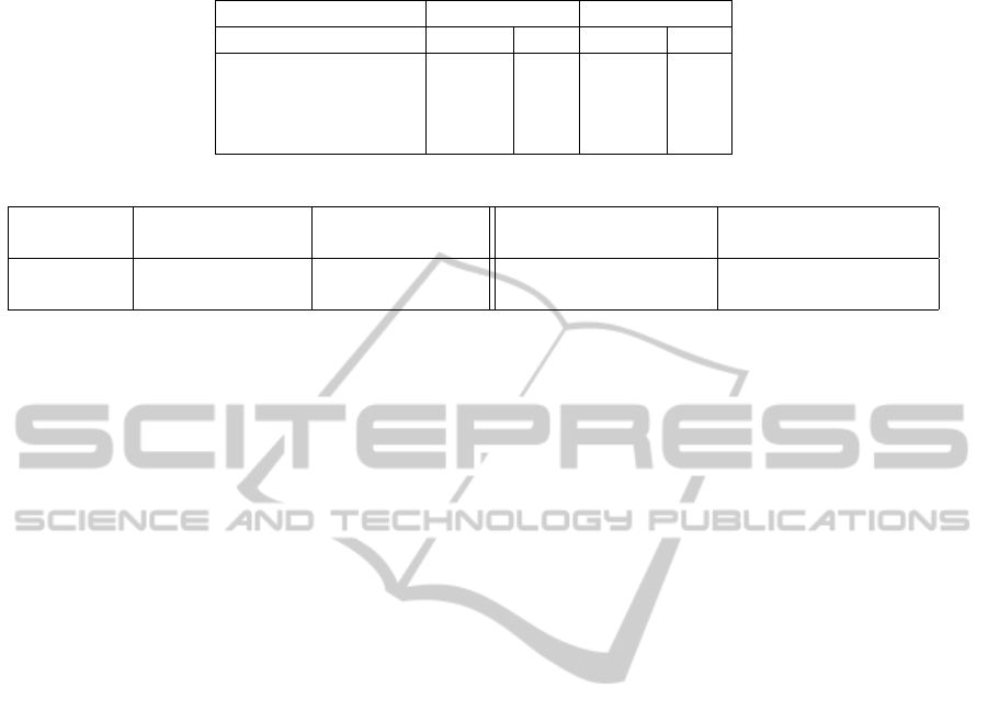
Table 4: Power consumption of each part of the system.
Face Orchard
Power consumption (Watt) (%) (Watt) (%)
Algorithm 7,39 17,2 3,55 9,6
Board weight 7 16,3 5 13,5
UAV weight 26 60,6 26 70
IMU 2,55 5,9 2,55 6,9
Table 5: Deviation between estimated and measured data.
Algorithm Estimated speed Measured speed Estimated flight time Measured flight time
(fps) (fps) (min) (min)
Face 5,06 4,9 11,6 12,4
Orchard 14,8 14,97 13,4 12,7
of the algorithm can’t be ignored when using small
UAVs.
Secondly, we verified the estimated flight time by
attaching the proposed hardware platform on the AR
Drone while running the specific algorithm. Flight
time is measured while hovering, as seen in Table 5
the deviation between estimated and measured data is
very small (less than 7%) indicating that our frame-
work indeed finds the best hardware platform for a
specific vision algorithm and estimates the speed and
flight time very precisely. Note that, when the AR
Drone runs the orchard or face algorithm the flight
time reduces with 30.21% and 39.58% as compared
to the flight time without payload.
6 CONCLUSION AND FUTURE
WORK
We developed a framework that finds the best hard-
ware platform for a specific vision processing algo-
rithm that should run at a certain speed on-board a
UAV. Furthermore the speed of the algorithm running
on each platform is estimated. Thanks to this frame-
work researchers can find a suitable hardware plat-
form without buying them all to test their algorithm
on. A second novelty of our framework is that flight
time can be estimated for the user’s UAV, carrying the
proposed platform. We validated the framework with
success on two real test cases allowing us to find a
suitable hardware platform for our application and to
estimate the flight time with our AR Drone carrying
this platform.
Also, we made this model available via an
online front end that other researchers can use
to find the best platform for their algorithm and
even add their own hardware to the framework
and expand the database of hardware platforms
(www.eavise.be/VirtualCameraman). In the future we
will keep adding new state-of-the-art platforms and
extend the framework with GPU platforms.
ACKNOWLEDGEMENTS
This work is funded by KU Leuven via the
CAMETRON project.
REFERENCES
Anthony, D., Elbaum, S., Lorenz, A., and Detweiler, C.
(2014). On crop height estimation with UAVs. In
Intelligent Robots and Systems (IROS 2014), 2014
IEEE/RSJ International Conference on, pages 4805–
4812. IEEE.
De Wagter, C., Tijmons, S., Remes, B. D., and de Croon,
G. C. (2014). Autonomous flight of a 20-gram flap-
ping wing MAV with a 4-gram onboard stereo vision
system. In Robotics and Automation (ICRA), 2014
IEEE International Conference on, pages 4982–4987.
IEEE.
Ehsan, S. and McDonald-Maier, K. D. (2009). On-board vi-
sion processing for small UAVs: Time to rethink strat-
egy. In Adaptive Hardware and Systems, 2009. AHS
2009. NASA/ESA Conference on, pages 75–81. IEEE.
Ferrick, A., Fish, J., Venator, E., and Lee, G. S. (2012).
UAV obstacle avoidance using image processing tech-
niques. In Technologies for Practical Robot Applica-
tions (TePRA), 2012 IEEE International Conference
on, pages 73–78. IEEE.
Forster, C., Pizzoli, M., and Scaramuzza, D. (2014). Svo:
Fast semi-direct monocular visual odometry. In Proc.
IEEE Intl. Conf. on Robotics and Automation.
Hulens, D. and Vanderstegen, M. (2012). UAV autonoom
laten vliegen in een boomgaard. Master’s thesis, Dept
of Industr.Eng., College University Lessius.
Kok, J., Gonzalez, L. F., and Kelson, N. (2013). FPGA
implementation of an evolutionary algorithm for au-
tonomous unmanned aerial vehicle on-board path
HowtoChoosetheBestEmbeddedProcessingPlatformforon-BoardUAVImageProcessing?
385

planning. Evolutionary Computation, IEEE Transac-
tions on, 17(2):272–281.
Lin, Y. and Saripalli, S. (2014). Path planning using 3d
dubins curve for unmanned aerial vehicles. In Un-
manned Aircraft Systems (ICUAS), 2014 International
Conference on, pages 296–304. IEEE.
McGee, T. G., Sengupta, R., and Hedrick, K. (2005). Ob-
stacle detection for small autonomous aircraft using
sky segmentation. In Robotics and Automation, 2005.
ICRA 2005. Proceedings of the 2005 IEEE Interna-
tional Conference on, pages 4679–4684. IEEE.
Meier, L., Tanskanen, P., Fraundorfer, F., and Pollefeys, M.
(2011). Pixhawk: A system for autonomous flight
using onboard computer vision. In Robotics and au-
tomation (ICRA), 2011 IEEE international conference
on, pages 2992–2997. IEEE.
Nieuwenhuisen, M. and Behnke, S. (2014). Hierarchical
planning with 3d local multiresolution obstacle avoid-
ance for micro aerial vehicles. In Proceedings of the
Joint Int. Symposium on Robotics (ISR) and the Ger-
man Conference on Robotics (ROBOTIK).
Prouty, R. W. (1995). Helicopter performance, stability,
and control.
Sa, I., Hrabar, S., and Corke, P. (2014). Inspection of pole-
like structures using a vision-controlled VTOL UAV
and shared autonomy. In Intelligent Robots and Sys-
tems (IROS 2014), 2014 IEEE/RSJ International Con-
ference on, pages 4819–4826. IEEE.
Shen, S., Mulgaonkar, Y., Michael, N., and Kumar, V.
(2013). Vision-based state estimation and trajectory
control towards high-speed flight with a quadrotor. In
Robotics: Science and Systems. Citeseer.
Siebert, S. and Teizer, J. (2014). Mobile 3d mapping for sur-
veying earthwork projects using an unmanned aerial
vehicle (uav) system. Automation in Construction,
41:1–14.
Suzuki, T., Amano, Y., and Hashizume, T. (2011). De-
velopment of a SIFT based monocular EKF-SLAM
algorithm for a small unmanned aerial vehicle. In
SICE Annual Conference (SICE), 2011 Proceedings
of, pages 1656–1659. IEEE.
Theys, B., Dimitriadis, G., Andrianne, T., Hendrick, P., and
De Schutter, J. (2014). Wind tunnel testing of a VTOL
MAV propeller in tilted operating mode. In ICUAS.
Verbeke, J., Hulens, D., Ramon, H., Goedem
´
e, T., and
De Schutter, J. (2014). The design and construction
of a high endurance hexacopter suited for narrow cor-
ridors.
Viola, P. and Jones, M. (2001). Rapid object detection using
a boosted cascade of simple features. In Computer Vi-
sion and Pattern Recognition, 2001. CVPR 2001. Pro-
ceedings of the 2001 IEEE Computer Society Confer-
ence on, volume 1, pages I–511. IEEE.
Wenzel, K. E., Masselli, A., and Zell, A. (2011). Auto-
matic take off, tracking and landing of a miniature
UAV on a moving carrier vehicle. Journal of intel-
ligent & robotic systems, 61(1-4):221–238.
VISAPP2015-InternationalConferenceonComputerVisionTheoryandApplications
386
