
Acquisition of Aerial Light Fields
Indrajit Kurmi and K. S. Venkatesh
Departement of Electrical Engineering, IIT Kanpur, Kanpur, U.P, India
Keywords:
Light Field, Unmanned Aerial Vehicle, State Estimation.
Abstract:
Since its inception in computer graphics community light field has drawn a lot of attention and interest. By
densly sampling the plenoptic function light fields present an alternative way to represent and produce a
faithful reconstruction of 3D scenes. But acquisition of densely sampled light fields require camera arrays,
robotic arms or newly developed plenoptic cameras. The light fields captured using the existential technologies
are limited to scenes containing limited complexity. In this paper we propose to use unmanned aerial vehicle
for acquisition of larger unstructured aerial light fields. We aim to capture light fields of larger objects and
scenes which are not possible by traditional light field acquisition setup. We combine the data from IMU
and state estimated using homography with a Kalman filter framework. Frames which gives a minimum
error (approximation of free form camera surface to traditional parameterization) are selected as perspective
images of light fields. Rendering algorithm is devised to support the unstructured camera surface and to avoid
rebinning of image data.
1 INTRODUCTION
In recent times image based rendering (IBR) has be-
come a popular alternative to traditional 3D graphics
in representing visual aspects of 3D scenes. In con-
trast to traditional polygonal rendering pipeline IBR
algorithms uses a collection of pre-acquired views to
generate new virtual views. Mostly this algorithms
do not depend on the scene depth information and it’s
complexity, which makes IBR a great technique to re-
alize photo-realistic image synthesis. Light field (one
of IBR techniques) has become increasingly practical
since its inception in computer graphics community.
Light fields densely sample the plenoptic function and
thus presents an alternative way to represent and pro-
duce a faithful reconstruction of 3D scenes.
Acquisition setup required to capture light fields
varies with the parameterization with which the light
field is represented. In 1996 Levoy and Han-
haran (Levoy and Hanrahan, 1996) and Gortler et
al. (Gortler et al., 1996) implemented 2PP (Two
plane parameterization). Levoy (Levoy and Hanra-
han, 1996) acquired light fields using a standard cam-
era array setup implemented in Standford University.
While Gortler (Gortler et al., 1996) used a video cam-
era along with depth information of the scene which
is difficult to acquire. Since then various other alter-
nate parameterization such as spherical light fields by
Ihm et al. (Ihm et al., 1997), cylindrical parameteri-
zation(Indrajit et al., 2014), two sphere parameteriza-
tion (Camahort et al., 1998) and sphere plane param-
eterization by Camahort et al. (Camahort et al., 1998)
have been proposed. But this parameterization also
requires complex robotic arm setup for acquisition of
light fields. Though nowadays various light field cam-
eras (eg. Lytro and Raytrix) are commercially avail-
able. But this cameras has very limited field of view.
Due to the complexity involved with acquisition of
light fields most of the work in light fields has been
focused on capturing of scenes with limited complex-
ity. The existential acquisition setup are limited by its
dimension and provides limited scene coverage.
Light field photography have various advantages
compared to digital photography, such as synthetic re-
focusing, multi-perspective recording, depth-variant
filtering, and much more. But the complexity in-
volved in the acquisition of light fields has con-
strained its application to scenes with limited com-
plexity. A simple way to acquire light fields will open
up its application to various different fields such as
scene reconstruction of a complex and detailed envi-
ronment for movie production.
Recent times has also seen tremendous develop-
ment in unmanned aerial vehicles. This has resulted
in capturing of scenes which were not possible long
before. UAVs can be remote controlled aircraft (e.g.
272
Kurmi I. and Venkatesh K..
Acquisition of Aerial Light Fields.
DOI: 10.5220/0005362002720277
In Proceedings of the 10th International Conference on Computer Vision Theory and Applications (VISAPP-2015), pages 272-277
ISBN: 978-989-758-089-5
Copyright
c
2015 SCITEPRESS (Science and Technology Publications, Lda.)
flown by a pilot at a ground control station) or can
fly autonomously based on pre-programmed flight
plans or more complex dynamic automation systems.
UAVs have been employed in surveying of objects
and ground on the basis of orthographic photos to
generate point clouds, volume calculations, digital
height and 3D models.
In this paper we propose to use UAVs to capture
unstructured light fields as an approximation to tradi-
tional light field parameterizations. For acquisition of
light fields, data from IMU and state estimated using
homography are combined with a Extended Kalman
filter framework . Frames which gives a minimum
error ( approximation of free form camera surface to
traditional parameterization) are selected as perspec-
tive images of light fields. The rendering algorithm is
devised to support the free from camera surface.
The rest of the paper is organized as follows. Sec-
tion 2 presents related work to acquire light fields.
Section 3 presents our proposed system to capture
light fields using UAV.
2 BACKGROUND AND RELATED
WORK
Most of the works in light fields has been focused on
acquisition of light fields of simple scenes. Here we
discuss some of the acquisition setups employed to
capture light fields. To our knowledge, acquisition of
light fields using UAVs has not been attempted. Here
we will also discuss some of works in which state of
UAVs have been estimated.
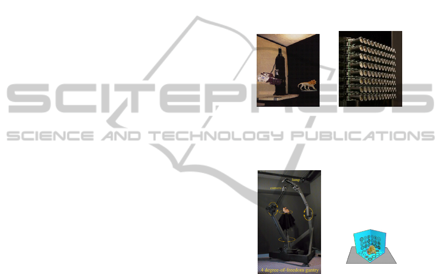
2.1 Light Field Acquisition
The light field rendering system utilizes a computer
controlled camera gantry such as shown in Figure 1(a)
and 1(b), which is based on a modified motion plat-
form with additional stepping motors. The setup, in
Figure 1(b), was later utilized for light field rendering
and consists of 128 camera array. The cameras are
mechanically setup and they are placed at a distance
from each other such that the whole set up works as
a multiple-center-of-projection camera to capture the
light field. Any displacement between cameras will
alter the sampling density and hence has to be care-
fully setup mechanically.
The lumigraph system follows a very inexpensive
but a complex approach. They capture the scene by
moving a handheld video camera through the scene.
Therefore, the cameras pose need to be estimated for
each frame. For finding the camera pose for each
frame, they use calibration markers in a specially de-
signed data capturing stage (Figure 2(b)). This also
presents an additional problem of interpolation of the
4 dimensional lumigraph from scattered data because
of the unstructured input. Gortler et al. (Gortler et al.,
1996) store a rough approximation of the object for al-
lowing depth corrections in the later stage. To recover
a geometric model of the scene, however, additional
effort has to be spent. 3D scanning technology as well
as sophisticated stereo vision and image based feature
extraction methods are applied to extract the geomet-
ric representation.
(a) Setup for Light field
rendering (lev, 1996)
(b) 128 camera array
built by Stanford graph-
ics laboratory (sta, 2004)
Figure 1: Light field acquisiton setup.
(a) Spherical gantry
(Sph, 2002)
(b) Setup used for lumi-
graph aquisition (Gortler
et al., 1996)
Figure 2: Different acquisiton setup.
In (Davis et al., 2012) the authors generate un-
structured 4D light fields by capturing views on and
around a sphere containing the desired object using a
hand held camera. But the scenes which can be cap-
tured are limited by our capability to form a bounding
sphere around the desired object. For other scenes a
complex, detailed and densely sampled light field ac-
quisition is impracticable.
Hence we propose to use UAVs to capture im-
ages which can be employed as perspective images
for light fields. This system provides capability to
capture detailed and densely sampled light fields for
various different complex scenes which were not pos-
sible previously. UAVs can be automatically guided
or manually driven which provides an option for ac-
AcquisitionofAerialLightFields
273

quisition of aerial light fields.
2.2 UAVs State Estimation
The pose and position of the UAVs can be estimated
accurately and rapidly. The regular approach is to ap-
ply sensor fusion to the data from the inertial sen-
sors and other sensors. Some of the other sensors
used for this purpose are the Global positioning sen-
sor (GPS), inertial measurement unit (IMU), altitude
sensors (ALS) and speedometers. But all this sensors
have their individual limitations. For example, GPS
sensor data are unavailable at some locations or the
data is prone to error. Data error from IMU tends to
accumulate and hence proves disadvantageous when
used individually. The main reasons for the inaccura-
cies are gravity modeling, external disturbances and
sensor malfunctions.
Vision-based navigation approaches have been de-
veloped to overcome these limitations. These ap-
proaches can be used where GPS systems are not
available. The vision based algorithms (Roumeliotis
et al., 2002), (Lobo and Dias, 1998) and (Laboratoire
et al., 2002) can be used with other sensors to obtain
better state and position estimation. State of UAV X
is denoted as
X = [X, Y, Z, V
x
, V
y
, V
z
, ω
x
, ω
y
, ω
z
, θ, ψ, φ] (1)
where X, Y , Z are vehicle position; V
x
, V
y
, V
z
are linear velocities; ω
x
, ω
y
, ω
z
are angular veloc-
ities; θ, ψ, φ are Pitch, Roll and Yaw. This algo-
rithms (Roumeliotis et al., 2002), (Lobo and Dias,
1998) and (Laboratoire et al., 2002) are estimating ei-
ther complete vehicle state or some of the vectors of
vehicle state by combining the inertial measurements
either with bearings to known fiducials or from op-
tical flow data from different video algorithms. Diel
(Diel et al., 2005) presents a variant in which he uses
epipolar constraints for vision-aided inertial naviga-
tion. (Soatto et al., 1996) derived the implicit ex-
tended Kalman filter (IEKF) for estimating displace-
ment and rotation that incorporates an implicit formu-
lation into the framework of the IEKF on the random
walk model. The IEKF implementation was applied
on the non linear space to characterize the motion of
a cloud of feature points about a fixed camera. While
Marks (Marks, 1995) demonstrates real time naviga-
tion using camera as the primary sensor. A sonar
proximity sensor is employed to obtain distance from
nearest planar surface. And position offsets relative
to a reference image is obtained using texture corre-
lation. This capability has been adapted to enable un-
derwater station keeping (Leabourne et al., 1997) and
has been extended to incorporate additional sensors
(Richmond, 2009).
(Grabe et al., 2012) had use continuous homog-
raphy constraint (Ma et al., 2001) for linear velocity
estimation, integrated with the IMU for full state esti-
mation, i.e they partially estimated state using com-
puter vision. (Dusha et al., 2007) proposed algo-
rithm based on Kalman filter and optical flow for state
estimation. Their algorithm is not suitable for real
world scenario. Amidi (Amidi, 1996) describes vi-
sion aided navigation for an autonomous helicopter
where a stereo pair is used to aid in station keeping.
Sinopoli (Sinopoli et al., 2001) describe a system that
uses data from fused GPS/ INS and a digital elevation
map to plan coarse trajectories which are then refined
using data from a vision system. Roberts (Roberts
et al., 2003) describes a flight control system for a he-
licopter that uses a stereo pair to determine altitude
and optical flow to determine ground speed.
In our formulation a complete UAV state is esti-
mated. The position and pose is computed by fusing
the Measurements from IMU and visual odometery in
a extended kalman filter framework.
3 LIGHT FIELD ACQUISITION
USING UAVs
Our acquisition system is as depicted in Figure 3.
The system contains a flight path planner which can
be done automatically or manually, a state estimator
which estimate position and pose of each frame of the
video acquired. To improve the accuracy of position
and pose estimated we combine the state estimated
using IMU and videos using a kalman filter frame-
work. Once the position and pose of each frame is
estimated, we select the frames which lowers the er-
ror in position difference between an approximated
free form camera surface and a traditional light field
parameterization. The frame position and pose data is
also given to the Flight path planner where it shows
the coverage of the scenes for each frames. Using this
coverage data the flight path planner can decide the
path which takes images from an undersampled area.
Once the whole scene is densely sampled we render
virtual views from the frame selected using our ren-
dering algorithm.
3.1 Flight Path Planner
The flight path planner can be automatically or man-
ually controlled. An user interface shows the scene to
be captured. Once the scene to be captured is selected
by the user an appropriate approximation of the cam-
era surface is overlayed on the scene. This overlayed
camera surface will demonstrate the state of the frame
VISAPP2015-InternationalConferenceonComputerVisionTheoryandApplications
274
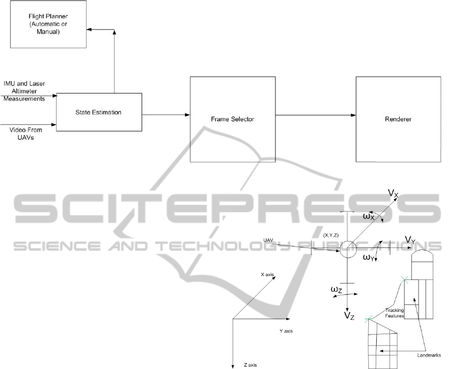
Figure 3: Acquisition System To Capture Light Fields Using UAVs.
captured. The aim of flight planner is to make assure
that the UAV traverse along the camera surface. This
is demonstrated on the overlayed camera surface with
colour coded information. As the UAV deviates from
the surface the state estimates turns red and as soon
as the UAV is on the overlayed camera surface the
state estimates turns green. This will help the user to
control the UAV when flight is manually controlled.
While manually controlling the user also needs to
make sure that the states estimated are uniformly dis-
tributed. An automatic flight controller continuously
monitors the UAVs state information and tries to plan
the flight path to minimize the error in the UAVs cur-
rent state estimate and the desired state.
3.2 State Estimation using IMU and
Camera
The system combines visual odometry with data from
IMU to estimate the state (position and attitude) of
the vehicle. Our solution is designed to take advan-
tage of complimentary IMU and camera sensor char-
acteristics. Rapid changes in angular rotation rates
and linear accelerations are accurately measured by
IMU. But measurement from IMUs are subject to un-
bounded low-frequency drift. Contrastingly estimates
obtained from Visual sensors are generally more ac-
curate when the cameras field of view changes rela-
tively slowly. By fusing their output, each sensor is
able to compensate for the weaknesses inherent in the
other.
Many visual odometry implementations use stereo
cameras, as stereo allows the depth of landmarks to
be calculated directly from known camera geome-
try. In (Amidi, 1996), Amidi et al. present a visual
odometer designed specifically for an autonomous he-
licopter. They estimate vehicle attitude using gyro-
Figure 4: State estimation of UAVs.
scopes and vehicle position by tracking ground tar-
gets with stereo cameras. However our system oper-
ates with either monocular imagery. An EKF is used
to fuse monocular camera, laser altimeter, and IMU
data. In our system we track point landmarks across
image frames, and find the incremental change in
camera pose by aligning corresponding sets of land-
mark positions. Visual and inertial measurements are
fused in an extended Kalman filter (EKF) to produce
an estimate of the vehicle state. We use the contin-
uous discrete formulation of the EKF, in which the
state estimate is propagated according to the under-
lying continuous-time non-linear system dynamics,
while measurement updates are made at discrete time
steps. Our state vector includes the position of the
UAV in the global frame, the velocity of the helicopter
in the body frame, the attitude of the helicopter. Fur-
ther details on the EKF implementation are available
in(Saripalli et al., 2003).
AcquisitionofAerialLightFields
275

3.3 Frame Selector
Once all the frame position and pose is estimated,
frames which gives a minimum error(approximation
of free form camera surface to traditional parameter-
ization) are selected as perspective images of light
fields.
min
∑
(A
position
∗ Error
position
+ A
pose
∗ Error
pose
)
(2)
Error
position
= A
X
∗ E
X
+ A
Y
∗ E
Y
+ A
Z
∗ E
Z
(3)
Error
pose
= A
θ
∗ E
θ
+ A
ψ
∗ E
ψ
+ A
φ
∗ E
φ
(4)
The weightage A given to each error E is decided
after performing an error analysis. For example, error
in measurements of X, Y coordinates E
X
, E
Y
will re-
sult in less error overall than error E
Z
in measurement
of Z. Similarly the pose errors E
θ
, E
ψ
and E
φ
weigh-
tage A
θ
, A
ψ
and A
φ
will increase substantially once
error increase certain threshold angles. A detailed er-
ror analysis is required to assign the weightage to each
error in measurement.
3.4 Renderer
Our system proposes a light field rendering technique
that directly renders views from an unstructured col-
lection of input images. Along with the unstructured
collection of source images, their associated camera
position and pose estimates are applied as input to our
renderer. A camera blending field is evaluated at a set
of vertices in the desired image plane and this field is
interpolated over the whole image. A simple blend-
ing field is not sufficient for unstructured light field.
Hence, for constructing pixels of virtual views differ-
ent weights is assigned to the different source cam-
eras. The blending field describes how the weight has
been assigned to each cameras. Factors related to ray
angular difference, estimates of undersampling, and
field of view are also considered while calculating the
blending field.
A threshold is set over the ray angular differences.
As the angle differences increase from the threshold
the blending weight will decrease from one to zero.
We employ and adaptive way to compute the blend-
ing weight. We consider the closest k source cameras
with smallest angle difference. In this case we must
take care that a particular cameras blending weight
falls to zero as it leaves the set of n closest cameras.
This is accomplished by combining the criterion of n
closest cameras and the angular threshold.
To reconstruct a pixel, we do not want to use
source cameras that significantly under sample the ob-
served point p. Since we know the positions of the
cameras and their fields of view we compute an ac-
curate prediction of the degree of undersampling at
observed point p. Similarly we do not want to select
cameras in n closest cameras, for which the ray from
which pixel to be reconstructed falls out of the cam-
eras field of view. Hence we create a weight func-
tion which changes from one to zero as the camera
selected undersamples the point or ray fall outside its
field of view.
4 CONCLUSIONS
We have presented a system to unstructured aerial
light fields as an approximation to the traditional light
field parameterization using UAVs. Acquisition of
light fields using UAVs presents tremendous oppor-
tunities to capture aerial light field of scenes. The
presented system calculates the UAVs state using an
EKF framework. The framework combines the data
from the IMU, laser altimeter and measurements ob-
tained using camera. An autonomous flight planner is
presented to reduce the error by maintaining the state
of UAVs close to the overlayed camera surface. The
presented frame selector assigns different weights to
different measurement according to the error analysis.
We are currently simulating the conditions in C++ and
OpenGL Platform for error analysis. Following the
simulation we are aiming to capture aerial light fields
using the presented system.
There are also other challenges in capturing larger
aerial light fields such as caching or compression of
light field data while rendering, which we have not
addressed here. The future work will also involve de-
veloping a caching or compression algorithm pertain-
ing to unstructured aerial light fields.
REFERENCES
(1996). Setup used for light field rendering. http://graphics.
stanford.edu/papers/light/gantry preview.jpg.
(2002). The stanford spherical gantry. http://graphics.
stanford.edu/projects/gantry.
(2004). The stanford multi-camera array. http://graphics.
stanford.edu/projects/array.
Amidi, O. (1996). An Autonomous Vision-Guided Heli-
copter. PhD thesis, Citeseer.
Camahort, E., Lerios, A., and Fussell, D. (1998). Uniformly
sampled light fields. pages 117–130. Springer Verlag.
Davis, A., Levoy, M., and Durand, F. (2012). Unstructured
light fields. Comp. Graph. Forum, 31(2pt1):305–314.
Diel, D. D., DeBitetto, P., and Teller, S. (2005). Epipo-
lar constraints for vision-aided inertial navigation. In
VISAPP2015-InternationalConferenceonComputerVisionTheoryandApplications
276

In EEE Workshop on Motion and Video Computing,
pages 221–228.
Dusha, D., Boles, W., and Walker, R. (2007). Attitude es-
timation for a fixed-wing aircraft using horizon de-
tection and optical flow. In Digital Image Comput-
ing Techniques and Applications, 9th Biennial Con-
ference of the Australian Pattern Recognition Society
on, pages 485–492.
Gortler, S. J., Grzeszczuk, R., Szeliski, R., and Cohen, M. F.
(1996). The lumigraph. In Proceedings of the 23rd
Annual Conference on Computer Graphics and In-
teractive Techniques, SIGGRAPH ’96, pages 43–54,
New York, NY, USA. ACM.
Grabe, V., Blthoff, H. H., and Giordano, P. R. (2012). On-
board velocity estimation and closed-loop control of a
quadrotor uav based on optical flow. In ICRA, pages
491–497. IEEE.
Ihm, I., Park, S., and Lee, R. K. (1997). Rendering of spher-
ical light fields. In Proceedings of the 5th Pacific Con-
ference on Computer Graphics and Applications, PG
’97, pages 59–, Washington, DC, USA. IEEE Com-
puter Society.
Indrajit, K., Venkatesh, K., and Sumana, G. (2014).
True zoom with cylindrical light feld system. In
Chmielewski, L., Kozera, R., Shin, B.-S., and Woj-
ciechowski, K., editors, Computer Vision and Graph-
ics, volume 8671 of Lecture Notes in Computer Sci-
ence, pages 278–285. Springer International Publish-
ing.
Laboratoire, N. F., Netter, T., and Franceschini, N. (2002).
A Robotic Aircraft that Follows Terrain Using a Neu-
romorphic Eye Thomas Netter. In Conf. Intelligent
Robots and System, volume 1, pages 129–134.
Leabourne, K., Rock, S., Fleischer, S., and Burton, R.
(1997). Station keeping of an rov using vision tech-
nology. In OCEANS ’97. MTS/IEEE Conference Pro-
ceedings, volume 1, pages 634–640 vol.1.
Levoy, M. and Hanrahan, P. (1996). Light field render-
ing. In Proceedings of the 23rd Annual Conference
on Computer Graphics and Interactive Techniques,
SIGGRAPH ’96, pages 31–42, New York, NY, USA.
ACM.
Lobo, J. and Dias, J. (1998). Integration of inertial infor-
mation with vision. In Industrial Electronics Soci-
ety, 1998. IECON ’98. Proceedings of the 24th Annual
Conference of the IEEE, volume 3, pages 1263–1267
vol.3.
Ma, Y., Ko
ˇ
seck
´
a, J., Soatto, S., and Sastry, S. (2001). An
invitation to 3-d vision.
Marks, R. L. (1995). Experiments in Visual Sensing for Au-
tomatic Control of an Underwater Robot. phd, Stan-
ford University, Stanford, CA 94305. Also published
as SUDAAR 681.
Richmond, K. (2009). Real-time visual mosaicking and
navigation on the seafloor. ProQuest.
Roberts, J., Corke, P., and Buskey, G. (2003). Low-cost
flight control system for a small autonomous heli-
copter. In Robotics and Automation, 2003. Proceed-
ings. ICRA ’03. IEEE International Conference on,
volume 1, pages 546–551 vol.1.
Roumeliotis, S. I., Johnson, A. E., and Montgomery, J. F.
(2002). Augmenting inertial navigation with image-
based motion estimation. In ICRA, pages 4326–4333.
IEEE.
Saripalli, S., Roberts, J. M., Corke, P. I., Buskey, G., and
Sukhatme, G. (2003). A tale of two helicopters. In In-
telligent Robots and Systems, 2003.(IROS 2003). Pro-
ceedings. 2003 IEEE/RSJ International Conference
on, volume 1, pages 805–810. IEEE.
Sinopoli, B., Micheli, M., Donato, G., and Koo, T. (2001).
Vision based navigation for an unmanned aerial vehi-
cle. In Robotics and Automation, 2001. Proceedings
2001 ICRA. IEEE International Conference on, vol-
ume 2, pages 1757–1764 vol.2.
Soatto, S., Frezza, R., and Perona, P. (1996). Motion esti-
mation via dynamic vision. Automatic Control, IEEE
Transactions on, 41(3):393–413.
AcquisitionofAerialLightFields
277
