
Deriving a Data Model from a Set of Interrelated Business Process
Models
Estrela F. Cruz
1,2
, Ricardo J. Machado
2
and Maribel Y. Santos
2
1
Instituto Polit
´
ecnico de Viana do Castelo, Viana do Castelo, Portugal
2
Centro ALGORITMI, Escola de Engenharia, Universidade do Minho, Guimar
˜
aes, Portugal
Keywords:
Business Process Modeling, BPMN, Data Model.
Abstract:
Business process modeling and management approaches are increasingly used and disclosed between organi-
zations as a means of optimizing and streamlining the business activities. A business process model identifies
the activities, resources and data involved in the creation of a product or service, having lots of useful infor-
mation that can be used to create a data model for the supporting software system. A data model is one of
the most important models used in software development. Usually an organization deals with several business
processes. As a consequence a software product does not usually support only one business process, but rather
a set of business processes. This paper proposes an approach to generate a data model, based on a set of
interrelated business processes, modeled in BPMN language. The approach allows aggregating in one data
model all the information about persistent data that can be extracted from the set of business process models
serving as a basis for the software development.
1 INTRODUCTION
Markets’ globalization and the constant increase of
competition between companies demand constant
changes in organizations in order to adapt themselves
to new circumstances and to implement new strate-
gies. Organizations need to have a clear notion of
their internal processes in order to increase their ef-
ficiency and the quality of their products or services,
increasing the benefits for their stakeholders. For
this reason, many organizations adopt a business pro-
cess management (BPM) approach. BPM includes
methods, techniques, and tools to support the design,
enactment, management, and analysis of operational
business processes (van der Aalst, 2004). A business
process is a set of interrelated activities that are ex-
ecuted by one, or several, organizations working to-
gether to achieve a common business purpose (Ko,
2009; Hammer and Champy, 2001).
Among the various existing modeling languages,
we opted for the Business Process Model and Nota-
tion (BPMN), currently in version 2.0 (OMG, 2011),
because it is a widespread OMG standard that is very
well accepted and actually used in companies and
organizations (Recker, 2008; Aagesen and Krogstie,
2015). Besides, it is a complete language that allows
creating detailed business process models (OMG,
2011).
Usually a business process model is created with a
level of abstraction higher than the one needed in soft-
ware models (Cockburn, 2001). Nevertheless BPMN
2.0 allows to model details that are very useful in soft-
ware development. In software development differ-
ent models are usually used to represent different per-
spectives. The data model is one of the most impor-
tant models for designing software applications, rep-
resenting and organizing data, how it is stored and ac-
cessed, and the relationships among different entities.
From a data point of view, a business process model
has lots of information that can be used to create a
data model. But can a data model be created based on
the information we have in a set of interrelated busi-
ness process models?
In this paper we present an approach to extract the
existing information about data (focusing our atten-
tion in persistent data) from a set of interrelated busi-
ness process models and create a data model that can
be used as a basis for developing a supporting soft-
ware system.
An approach to obtain the data model based on
a single BPMN private business process model has
already been presented, by the same authors (Cruz
et al., 2012). The presented approach allows obtain-
ing an initial data model that can serve as a basis
49
F. Cruz E., J. Machado R. and Y. Santos M..
Deriving a Data Model from a Set of Interrelated Business Process Models.
DOI: 10.5220/0005366100490059
In Proceedings of the 17th International Conference on Enterprise Information Systems (ICEIS-2015), pages 49-59
ISBN: 978-989-758-097-0
Copyright
c
2015 SCITEPRESS (Science and Technology Publications, Lda.)

for further development. However, some limitations
were identified in the proposed approach, namely the
impossibility of identifying some of the relationships
between the entities represented in the data model,
the optionality of some association ends is not ad-
dressed, and the most significant limitation is the fact
that the approach only deals with one business pro-
cess model. However, a software application usu-
ally supports more than one single business process.
Consequently, the approach presented in (Cruz et al.,
2012) could not integrate in one data model all the
data involved in all business processes that must be
supported by the software under development.
The approach presented herein extends and com-
pletes the approach presented in (Cruz et al., 2012)
allowing the aggregation of the existing information
spanning several related business process models into
one data model. The proposed approach allows iden-
tifying the entities involved, the corresponding at-
tributes and the relations (including cardinality and
optionality) between the entities.
The remainder of this paper is structured as fol-
lows. In the next section, BPMN and basic concepts
of data model are introduced and some related work
is presented. Section 3 describes the approach be-
ing presented here for data model creation based on
a set of business processes. The application of the
proposed approach is illustrated through a demonstra-
tion case in section 4. Finally, section 5 analyzes the
generated data model, and section 6 draws some con-
clusions.
2 BACKGROUND
This section briefly describes the BPMN language
and concepts about data models, and also presents re-
lated work relevant to the proposed approach.
2.1 The BPMN Language
Business process management focus its attention on
designing and documenting business processes, in or-
der to describe which activities are performed and
the dependencies between them (Meyer, 2010). The
BPMN basic process models can be grouped into Pri-
vate Business Processes or Public Processes (OMG,
2011). Public processes represent the interactions be-
tween a private business process and other processes
or participants. A private business process is a pro-
cess internal to a specific organization. Each private
business process is represented within a pool repre-
senting a participant. A participant represents a role
played in the process by a person, an organization’s
department or something involved in the process. The
process flow must be in one pool and should never
cross the pool boundaries. A pool can be divided into
several Lanes, for example, to represent the different
departments of an organization involved in the pro-
cess. The interaction between distinct private busi-
ness processes (represented by different Pools) can be
represented by incoming and outgoing messages.
The main BPMN diagrams’ graphical elements to
define the behavior of a business process are Activi-
ties, Gateways and Events (OMG, 2011). An activ-
ity represents a piece of work. A gateway is used
to control how the process flows and it can diverge
(splitting gateways) or converge (merging gateways)
the sequence flow. An event is something that hap-
pens during the course of a process and that affects the
process’s flow (Allweyer, 2010). Activities, Gateways
and Events are connected by sequence flows, repre-
senting the execution order (Allweyer, 2010). An as-
sociation may be used to link text annotations and
other artifacts with other BPMN graphical elements
(OMG, 2011).
During a process execution, resources and/or data
are used and produced. In fact, the information about
the data that flows through the process is very impor-
tant to the software development.
The data received, created or used during a pro-
cess execution can be represented by message flows
or data associations as shown in Table 1. A message
flow connects two pools, representing the message ex-
change between the two participants (OMG, 2011). A
message represents the content of a communication
between two Participants. Data associations connect
activities and data objects or data stores as represented
in Table 1.
Data that flows through a process are represented
by data objects. Persistent data are represented by
data stores. Persistent data are the ones that remain
beyond the process life cycle, or after the process ex-
ecution ends (OMG, 2011).
Data objects and data stores are exclusively used
in private process diagrams (OMG, 2011). That’s the
main reason why the approach presented in this paper
is based on private business processes.
In BPMN’s most recent version, the number of
graphical element has increased, including the data
store element representing persistent data. This way,
BPMN 2.0 allows business process models to be
highly detailed, including the identification of persis-
tent data (OMG, 2011). This is an important update
if one intends to use BPMN models as a basis for
the development of the software product that supports
the business processes. The proposed approach bene-
fits from detailed business process models, as highly
ICEIS2015-17thInternationalConferenceonEnterpriseInformationSystems
50

Table 1: The Data handling.
Data
Graphical
representation
Meaning
Data
Store
The activity reads infor-
mation from the data store
Data
Store
The activity writes infor-
mation in the data store
Data
Object
The activity receives a
data object
Data
Object
The activity sends a data
object
Message
The participant (activity)
sends a message to an ex-
ternal participant
Message
The participant receives a
message from an external
participant
detailed business process yields more complete data
models.
2.2 Data Model
The data model is used to structure the knowledge
about a specific domain and is a way to leverage the
elements (or concepts) of most interest on that domain
(Evans, 2011). It represents the key concepts of the
problem and the relationships between them. The key
concepts are also called entities.
An entity is something identifiable, or a concept in
the real world that is important to the modeling pur-
pose (Weske, 2010). The information, or the prop-
erties, about an entity are expressed through a set of
attributes (Weske, 2010). A relationship between two
entities is represented through an association between
those entities (Chen, 1976).
A relationship between two entities can be classi-
fied in two aspects, Cardinality and Optionality. Both
terms are used to denote the number of attributes in
a relation. Cardinality represents the maximum num-
ber of instances (one or many) of an entity in relation
to another entity. Relationship optionality represents
the minimum number of elements that exist on that
side of the relationship. It may be 1 (the relation is
mandatory) or 0 (the relation is not mandatory).
In what concerns to cardinality, three types of re-
lationships can be identified (Chen, 1976): mappings
(1 : n), (m : n) and (1 : 1).
Focusing in one side of a relationship type and
considering the optionality and cardinality together
we may have: 0 or 1 (represented as
), 1 ( ),
0 to many ( ) and 1 to many ( ).
2.3 Related Work
Although previous work about data modeling within
BPMN already exists, to our knowledge, some pre-
vious work is related with BPMN versions prior to
2.0 and none of them addresses the attainment of a
data model that operationally supports a set of busi-
ness processes. In some of these studies some flaws
have been identified, by the authors, especially in dis-
tinguishing persistent from non-persistent data.
Brambilla et al. (Brambilla et al., 2008) explore
BPMN for the generation of the data design, busi-
ness logic, communication and representation. The
authors separate the different concerns in different
model types and interpret the BPMN in order to meet
the needs of a Rich Internet Application. With re-
spect to the data, the authors use BPMN data objects
to identify the data involved. To distinguish between
persistent and volatile data, the authors have chosen
to identify, in the process model itself, persistent data
with a ‘P’ and volatile data with a ‘V’. In BPMN
most recent version (BPMN2.0) the notion of persis-
tent data can be represented by a data store (OMG,
2011).
Magnani and Montesi (Magnani and Montesi,
2009), after identifying the gaps in data modeling us-
ing BPMN, proposed an extension to BPMN 1.2 with
the aim of improving the representation of data. The
extension was named BPDMN (Business Process and
Data Modeling Notation). Some of the concepts pro-
posed, namely a way to identify the existence of per-
sistent data were included in BPMN 2.0 (Magnani and
Montesi, 2009) with the introduction of the data store,
although with a different graphic symbol.
Wohed et al. (Wohed et al., 2006) make an assess-
ment of BPMN capabilities, its strengths and weak-
nesses, to model a business process and conclude that,
in BPMN 1.2, data is only partially represented.
The approach presented by de la Vara et al. ex-
tends the BPMN 1.2 with task description improve-
ments. The approach also presents guidelines for the
specification of the domain classes diagram (de la
Vara et al., 2009). The approach works with the
BPMN 1.2 version where the distinction between
persistent and non-persistent data was not possible.
Meyer et al. extend BPMN data objects with anno-
tations to allow data dependency representation and
data instance differentiation (Meyer et al., 2013). The
presented approach is able to generate SQL queries
DerivingaDataModelfromaSetofInterrelatedBusinessProcessModels
51

from BPMN data objects (Meyer et al., 2013).
Brdjanin et al. propose an approach to obtain a
database design based on the information existing in
a UML activity diagram (Brdjanin et al., 2011). The
authors propose a direct mapping of all business ob-
jects to the respective classes. Each participant is also
mapped to a class. Associations between business ob-
jects and business process participants are based on
the activities performed on those objects (Brdjanin
et al., 2011).
All the approaches cited before that generate data
models from business process models base their anal-
ysis in only one business process model. But, typi-
cally, in a real situation, a software product supports
a reasonable number of business processes. So, in or-
der to generate a useful data model it will be neces-
sary to consider the set of business process models
that will be supported by the software under develop-
ment and join all information about persistent data in
a data model.
3 THE PROPOSED APPROACH
In the approach presented in (Cruz et al., 2012), data
stores and participants in the business process model
give origin to entities in the data model. The relation-
ship between those entities is deduced from the infor-
mation exchange between participants and the activi-
ties that manipulate the data stores.
The approach we are presenting here is an exten-
sion to the approach presented in (Cruz et al., 2012)
and previously briefly summarized. This extension,
intends to enable the derivation of a data model di-
rectly from a set of interrelated business process mod-
els by aggregating and merging the information about
the data derived from a set of interrelated business
processes.
This approach also complements the approaches
presented in (Cruz et al., 2014b; Cruz et al., 2015)
by aggregating in one data model the data involved
on the same group of business processes used to gen-
erate the use case model. This way we have the soft-
ware requirements identification (use case model) and
the data model based on the same set of business pro-
cesses, serving as starting point to the development of
the software that will support the processes and assur-
ing that the data model supports the identified require-
ments (Cruz et al., 2014a).
To do that, first it is needed to identify and specify
which business processes are to be supported by the
software under development, identifying the system
scope (Cruz et al., 2014a). Then it is necessary to
group, aggregate and merge in one data model all the
information about data derived from those business
processes.
When working with a set of interrelated business
process models it is natural to find a participant in-
volved in several business processes. Following the
same idea, we can say that a data store can also be
involved in several business processes.
Usually, interrelated business processes comple-
ment each other, meaning for example that when a
business process reads information from a data store,
that information can be written during the execution
of the same or another related business process.
3.1 Assumptions
The approach here proposed assumes that:
• A set of private business processes is considered,
and, in this scenario, each identified business pro-
cess is represented in one (main) pool that can be
divided in several lanes. The other participants
(pools) involved in the business process are con-
sidered as “external participants”.
• When an activity receives information (messages)
from an “external participant” and when that in-
formation must be kept beyond the process exe-
cution, that activity must write the received infor-
mation into a data store.
• A data object represents data (a document, etc.)
that an activity sends or receives. When the infor-
mation contained in that data object must be kept
beyond the process life cycle, the activity must
write the information in a data store.
• When a business process reads information from
a data store and no other business process writes
information in this data store, this can mean that
something is wrong (for example a business pro-
cess is missing) or that a link with another appli-
cation exists. The same happens when a business
process writes information in a data store that is
never used (or no other activity reads information
from that data store).
3.2 Rules to Generate the Data Model
To define a persistent data model one needs to iden-
tify the domain entities, their attributes, and the rela-
tionships between those entities (Weske, 2010). Fol-
lowing this reasoning, the proposed approach is di-
vided in three parts: first we are going to present a set
of rules to identify the entities, then the entities’ at-
tributes are identified, and, finally, we present a set of
rules to identify the relationships between the iden-
tified entities, including cardinality and optionality.
ICEIS2015-17thInternationalConferenceonEnterpriseInformationSystems
52

The rules are in accordance with, and extend, the rules
already presented in (Cruz et al., 2012). Some rules
presented in (Cruz et al., 2012) are rewritten and mod-
ified to be applied to a set of business processes.
The first set of rules, to identify the entities, is:
• R1: A data store, belonging to one of the selected
business process models, is represented by an en-
tity (with the same name) in the data model (Cruz
et al., 2012).
• R2: Data stores with the same name, involved
in several business processes, are represented by
the same entity (with the same name) in the data
model.
When data stores with the same name are involved
in more than one business process we assume that
they represent the same data store, so they will
be represented by the same entity in the generated
data model.
• R3: Each participant involved in one of the se-
lected business process models originates an en-
tity in the data model (Cruz et al., 2012).
• R4: Participants with the same name, involved in
more than one business process, are represented
by the same entity (with the same name) in the
data model.
Usually a participant is involved in several busi-
ness processes of an organization. When partic-
ipants with the same name are involved in more
than one business process we assume that they
represent the same participant, so they will be rep-
resented by the same entity in the data model.
• R5: Participants with the same name as data stores
are represented by the same entity (with the same
name) in the data model.
When we are working with several related busi-
ness processes usually the information about “ex-
ternal participants” is stored during one of those
processes. Afterwards, when joining a group of
related business processes, we can find partici-
pants and data stores with the same name. In that
case, they will be represented by the same entity
in the data model.
The rules to identify the entities’ attributes are:
• R6: The attributes of an entity derived from a data
store are the integration of all attributes involved
in all the data store manipulations during the busi-
ness processes execution.
As explained in (Cruz et al., 2012) each item from
a data store is represented as an entity attribute in
the data model. A data store can be manipulated
by several activities belonging to different (or the
same) business processes. Each activity may in-
volve different items giving origin to different at-
tributes of the entity that represents the data store
in the data model. To prevent loss of information,
all involved items must be represented as entity
attributes in the data model. We assume that at-
tributes with the same name represent the same
attribute.
• R7: The initial attributes of an entity that rep-
resents a participant (involved in one, or several
business processes) are id and name (Cruz et al.,
2012). When a participant is involved in several
business processes, the participant’s name is the
same, so the entity attributes are also the same (id
and name).
• R8: When an entity represents a participant and
a data store, the entity will aggregate all the at-
tributes representing all the items involved in data
store manipulations and the attributes belonging
to the participant’s representation (id and name).
The rules to identify the relationships between the
identified entities are explained next.
• R9: When a participant is responsible for an ac-
tivity that writes information in a data store, the
entity that represents the participant must be re-
lated with the entity that represents the data store.
A participant can perform a process (and an activ-
ity belonging to that process) several times, so the
relationship is (1:n) from the entity that represents
the participant to the entity that represents the data
store.
The relationship is mandatory on the side of the
entity that represents the participant because the
activity is always executed by someone playing
that role. Nevertheless it is not mandatory on the
side of the entity that represents the data store be-
cause this process may never be executed by a
particular participant. But the participant can be
involved in other processes.
• R10: When an activity that handles the data store
exchanges information with an “external partici-
pant” we can distinguish four different cases:
1. The activity receives information from the par-
ticipant and writes information in a data store
(see example in Figure 1). In this case, we as-
sume that the information stored is provided by
the participant so, the entity that represents the
data store is related with the entity that repre-
sents the participant.
2. The activity writes information in a data store
and sends information to the participants. We
assume that the same information is stored and
DerivingaDataModelfromaSetofInterrelatedBusinessProcessModels
53
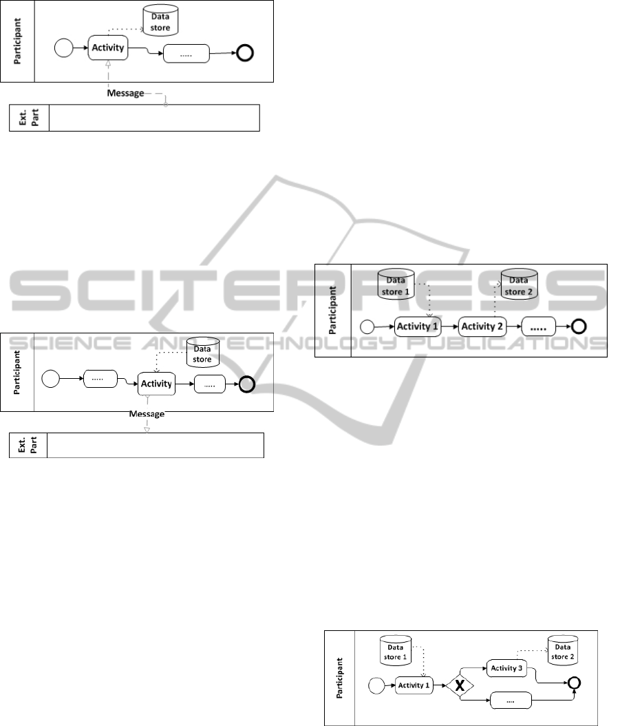
Figure 1: Receiving information from a participant.
sent to the participant (as for example a receipt
or a certificate) so, the entity that represents the
data store is related with the entity that repre-
sents the participant.
3. The activity reads information from a data store
and sends the information to an external partici-
pant (see Figure 2). We assume that the read in-
formation is provided to the participant so, the
entity that represents the data store is related
with the entity that represents the participant.
Figure 2: Sending information to a participant.
4. When an activity reads information from a data
store and also receives information from a par-
ticipant we assume that the activity is only
checking the information provided by the par-
ticipant which is already stored (probably dur-
ing the execution of another process). In this
case, there is no relationship between the iden-
tified entities.
In points 1, 2 and 3, the identified relationship
type is (1:n) from the entity that represents the
participant to the entity that represents the data
store (Cruz et al., 2012). Nevertheless, when the
activity that sends a message to a participant is
a looping activity, the relationship type is (m:n)
(Cruz et al., 2012). A Loop Activity is an ac-
tivity with looping behavior (cyclical or “multi-
instantiable”) (OMG, 2011) meaning that the ac-
tivity can be executed several times during one
process instance. Each Loop Activity instance
may have different values to the identified at-
tributes. So, if one loop activity is sending a mes-
sage to an external participant it may represent the
information being sent to several participants.
The relationship is mandatory on the side of the
entity that represents the participant because the
activity always interacts with someone playing
that role. On the side of the entity that represents
the data store it is not mandatory, because this pro-
cess may never be executed by a particular partic-
ipant.
• R11: When, during a process, an activity writes
information in a data store and, in a same process,
a previous activity reads information from another
data store (Figure 3), and between the activities
the process does not receive any other informa-
tion, it is assumed that the read and the written
information are related. As a consequence, the
two entities (representing the two data stores) are
related.
Figure 3: Relating two data stores.
As a process can be executed several times, the
same information can be read several times, so by
default the relationship type is (1:n) from the en-
tity that represents the read data store to the entity
that represents the written data store. If the activ-
ity that writes information is a looping activity the
relationship type is (m:n).
By default, the relationship is mandatory on both
sides. But, if the execution of the activity that
writes the information depends on a condition, for
example an exclusive decision gateway (see ex-
ample in Figure 4), then the relationship is not
mandatory on the side of the entity representing
the written data store.
Figure 4: Exclusive decision gateway example.
If the activity that writes information is performed
after a merging gateway (not a parallel join) (Fig-
ure 5), then the relationship is not mandatory on
the side of the entity representing the read data
store because the activity that reads the data store
may not be executed.
ICEIS2015-17thInternationalConferenceonEnterpriseInformationSystems
54
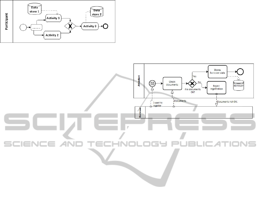
Figure 5: Exclusive merging gateway example.
• R12: All the relationships derived from the sev-
eral business processes must be preserved in the
data model.
A data store may be manipulated by several activi-
ties belonging to distinct (or to the same) business
processes, giving origin to different relationships.
To prevent the loss of information all the relation-
ships must be represented in the generated data
model (for further evaluation).
• R13: If, between two entities, there are differ-
ent relationship types, the relationship type with
higher cardinality prevails.
A data store can be manipulated by different ac-
tivities. If an activity is a looping activity and an-
other activity is not, it will originate relationship
types with different cardinalities. In that case, the
relationship with higher cardinality prevails.
• R14: If, between two entities, there are rela-
tionships with different mandatory types, the not
mandatory type prevails.
4 DEMONSTRATION CASE
In this section we use, as a demonstration case, a
very well-known example of a School Library Sys-
tem where a group of five related business process
models (in BPMN) have been selected to be presented
here. The selected business processes are: Register
User (Figure 6), Lend a Book (Figure 7), Reserve a
Book (Figure 8), Renew a Loan (Figure 9) and Return
a Book (Figure 10). The Return a Book business pro-
cess model includes a sub-process, Penalty treatment
represented in Figure 11. In this example, we are go-
ing to see that the business processes do not totally
complement each other.
The participants involved in all the five selected
business processes are the same: Borrower and At-
tendant. The two corresponding entities, with the
same name, must be represented in the resulting data
model.
The Register User business process model (Figure
6) stores information in the Borrower data store, so
the Borrower must be represented as an entity in the
data model. The Borrower entity has been identified
previously as representing a participant so, by R3, the
data store and the participant will be represented by
the same entity (Borrower). The Attendant participant
is responsible for executing the activity that writes in-
formation in the Borrower data store so, by R9, the
Attendant entity is related with the Borrower entity.
The relationship type is (1:n) and it is not mandatory
on the side of the Borrower entity.
Figure 6: Register User business process model.
In the Lend a Book business process model (Fig-
ure 7) three data stores are involved: Borrower, Book
and Loan. Borrower has already been identified as
an entity. Book and Loan will originate new entities,
with the corresponding name, in the data model. The
Attendant participant is responsible for writing infor-
mation in Loan data store so, by R9, the Attendant en-
tity is related with Loan entity. The relationship type
is (1:n).
In the same business process model (Lend a
Book), the Register Loan activity sends information
to the Loan data store and sends a message about
it to the Borrower participant so (by R10) the Loan
and Borrower entities are related. The relationship
type is (1:n) because a process can be executed sev-
eral times meaning that a Borrower can have several
loans. From another point of view, during the Lend
a Book business process execution, the activity Reg-
ister Loan sends information to the Loan data store
after the activity Check Book Status read information
from the Book data store. So, by R11, Book and Loan
entities are related. The relationship type is (1:n). The
relation is not mandatory on the side of the Loan en-
tity because the activity that writes information is only
executed if the gateway condition (is book available?)
is true.
The Reserve a Book business process (Figure 8)
involves three data stores: Borrower, Book and Reser-
vation. Borrower and Book were already identified
meaning that only Reservation will be appended as
an entity to the data model. The Attendant participant
writes information in the Reservation data store so, by
R9, the Attendant entity is related with the Reserva-
tion entity. The relationship type is (1:n). In the same
DerivingaDataModelfromaSetofInterrelatedBusinessProcessModels
55
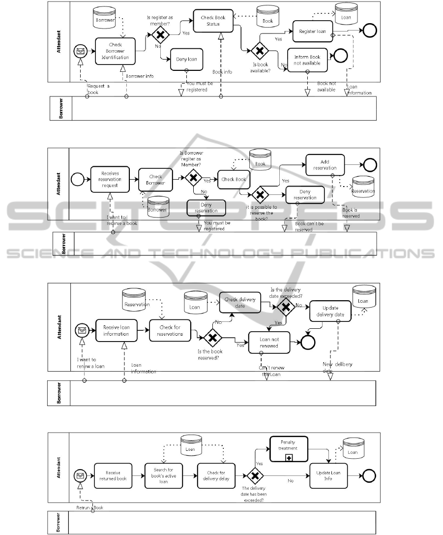
Figure 7: Lend a Book business process model.
Figure 8: Reserve a Book business process model.
Figure 9: Renew a Loan business process model.
Figure 10: Return a Book business process model.
business process, the Check Book activity reads infor-
mation from Book and the activity executed immedi-
ately after (Add reservation) writes information in the
Reservation data store. By R11, the two correspond-
ing entities are related (Book and Reservation). The
relationship type is (1:n). The relation is not manda-
tory on the side of the Reservation entity because the
activity that writes information is only executed if the
gateway condition (is possible to reserve the book?)
is true.
ICEIS2015-17thInternationalConferenceonEnterpriseInformationSystems
56
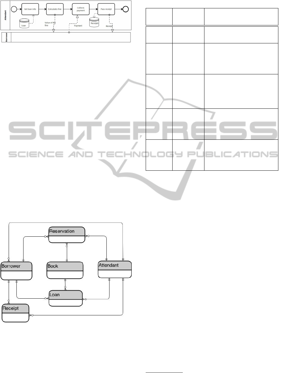
Figure 11: Penalty treatment business process model.
The Renew a Loan business process model (Fig-
ure 9) involves the data stores Loan and Reservation,
which are already represented in the data model.
In the Return a Book business process model (Fig-
ure 10), more exactly in the Penalty Treatment sub-
process (Figure 11), a new data store, Receipts, is
identified so, the corresponding entity must be repre-
sented in the final data model. The Pass Receipt activ-
ity writes information on the Receipts data store and
sends information to the Borrower participant, so (by
R10) the entities Borrower and Receipts are related
and the relationship type is (1:n). The Pass Receipt
activity is performed by the Attendant participant, so
(by R9) the Attendant and Receipts are related and the
relationship type is (1:n).
Because none of the activities is cyclic or “multi-
instantiable”, there are no (m:n) relationship types in
the resulting data model.
All identified entities (originated by participants
and data stores) and the relationships identified in
each process are presented in Table 2.
The resulting data model is shown in Figure 12.
Figure 12: The resulting data model.
5 ANALYZING THE RESULTS
The inclusion of the data store graphical element in
the BPMN most recent version, BPMN2.0 (OMG,
2011), allows the identification of the persistent data
Table 2: Entities and Relationships.
Business
Process
Entities
Relationships
Register
User
Attendant
Borrower
Attendant-Borrower(1:n) R9
Lend a
Book
Attendant
Borrower
Book
Loan
Attendant-Loan(1:n) R9
Borrower-Loan(1:n) R10
Book-Loan(1:n) R11
Reserve
a Book
Attendant
Borrower
Book
Reservation
Attendant-Reservation(1:n)
R9
Borrower-Reservation(1:n)
R10
Book-Reservation(1:n) R11
Renew a
Loan
Attendant
Borrower
Loan
Reservation
Attendant-Loan(1:n) R9
Borrower-Loan(1:n) R10
Return a
Book +
Penalty
treatment
Attendant
Borrower
Loan
Receipt
Attendant-Loan(1:n) R9
Attendant-Receipt(1:n) R9
Borrower-Receipt(1:n) R10
involved in a business process. As a consequence,
joining the set of business processes that will be sup-
ported by the software under development, we are ca-
pable of collecting all the information about persis-
tent data involved in those business processes. In fact,
analyzing the generated data model (Figure 12) we
may say that, from a group of related business pro-
cess models, we are able to generate a complete data
model identifying all the entities involved, all the at-
tributes
1
and all the relationships between the entities,
including optionality and cardinality.
By R12, all relationships are represented in the fi-
nal data model, so in some situations, especially when
a large number of business processes are involved, it
may originate redundant relationships. As a conse-
quence, the resulting data model should be analyzed
and checked before moving on to the next step of the
development process.
We mentioned previously that, usually, related
business processes complement each other. To sup-
port this idea, all operations performed during the
processes’ execution, in what concerns persistent data
manipulation, are summarized in Table 3.
Analyzing the data presented in Table 3 we may
conclude that the business processes complete each
1
The attributes identification is not highlighted here as it
was already addressed in (Cruz et al., 2012).
DerivingaDataModelfromaSetofInterrelatedBusinessProcessModels
57

Table 3: Entities manipulation.
Data Store
Process writes
information
Process reads
information
Borrower
Register User
Lend a Book
Return a Book
Renew a Loan
Loan
Lend a Book
Return a Book
Renew a Loan
Return a Book
Renew a Loan
Book
—
Lend a Book
Reserve a Book
Reservation Reserve a Book
Lend a Book
Renew a Loan
Receipt Penalty treatment
—
other, because the information written by one process
is, most of the times, used in another business process.
But, we may also see that the Book entity (represent-
ing a data store) is not updated/inserted by any activity
of the selected business processes but it is used (read)
in several business process models. Following the
same reasoning, the Receipts entity is never used or
read by any activity of the selected business processes
but during the Penalty Treatment sub-process execu-
tion, information is stored. The reason why this hap-
pens must be verified. In this particular case, the most
probable reason is because the selected set of busi-
ness processes is not complete. In fact the Purchase
books business process which writes in the book data
store is not included in the selected set, and the in-
formation about receipts is accessed from an external
accounting system that supports the organization’s ac-
counting process.
6 CONCLUSIONS AND FUTURE
WORK
It is recognized that detailed information about busi-
ness processes can help to ensure that the software
under development will really meet business needs
(Mili et al., 2003; Giaglis, 2001; Cruz et al., 2014a).
BPMN has increased its importance as a business pro-
cess modeling language and it is becoming more com-
plete. The most recent version allows identifying de-
tailed business process, including distinguishing per-
sistent from non-persistent data (OMG, 2011; All-
weyer, 2010).
From a software development point of view, one
of the most important, and used models is the data
model. The approach presented here derives a data
model based on the existing information in a set of
interrelated business processes. When we are work-
ing with only one business process, the generated data
model may be incomplete (Cruz et al., 2012) but,
by joining together a set of interrelated business pro-
cesses we are able to get a much more complete data
model because usually the information is shared by
a set of related business processes, belonging to an
organization. Often, the data written by a business
process is used by another (or the same) business pro-
cess.
The generated data model will help to ensure the
alignment between business processes and the soft-
ware that support them. However, it is necessary to
note that if the business process models will provide
the basis for the software development, they have to
cover all the relevant information, including the infor-
mation about the data involved in the process. The ap-
proach here presented needs highly detailed business
process models especially in what concerns to data.
This can make a business process model too com-
plex and can affect its main objective, which is the
description of the business process flow in a way that
is understandable by all stakeholders. To serve both
objectives, multiple perspectives of the model, each
focusing on a specific aspect, can be created. Another
solution is to develop business process modeling tools
able to allow the hide/unhide some details to represent
the several views and to improve understandability of
a specific aspect (Meyer et al., 2013).
It can be said that the BPMN models, if cor-
rectly created, support the automatic generation of the
proper data model, serving as a basis to the software
development. The approach presented here can also
be used to verify the completeness of the involved
business processes (in terms of persistent data) and/or
to identify possible links with other applications.
In (Weber et al., 2011) the authors conclude that,
usually, business process models have bad quality. An
effort to improve processes’ quality and completeness
is needed. The approach presented here is a step in
that direction.
As future work, we intend to apply this approach
in a real industrial scenario which complexity and di-
mension will benefit from a systematic approach to
the identification of the data model.
ACKNOWLEDGEMENTS
This work has been supported by FCT - Fundac¸
˜
ao
para a Ci
ˆ
encia e Tecnologia in the scope of the
project: PEst-UID/CEC/00319/2013.
ICEIS2015-17thInternationalConferenceonEnterpriseInformationSystems
58

REFERENCES
Aagesen, G. and Krogstie, J. (2015). BPMN 2.0 for model-
ing business processes. In vom Brocke, J. and Rose-
mann, M., editors, Handbook on Business Process
Management 1, International Handbooks on Informa-
tion Systems, pages 219–250. Springer Berlin Heidel-
berg.
Allweyer, T. (2010). BPMN 2.0 - Introduction to the stan-
dard for business process Modeling. Books on De-
mand GmbH, Norderstedt.
Brambilla, M., Preciado, J. C., Linaje, M., and Sanchez-
Figueroa, F. (2008). Business process-based concep-
tual design of rich internet applications. Web Engi-
neering, International Conference on, 0:155–161.
Brdjanin, D., Maric, S., and Gunjic, D. (2011). Adbdesign:
An approach to automated initial conceptual database
design based on business activity diagrams. In Ad-
vances in Databases and Information Systems, pages
117–131. Springer.
Chen, P. P.-S. (1976). The entity-relationship model toward
a unified view of data. ACM Trans. Database Syst.,
1:9–36.
Cockburn, A. (2001). Writing Effective Use Cases. Addison
Wesley.
Cruz, E. F., Machado, R. J., and Santos, M. Y. (2012).
From business process modeling to data model: A
systematic approach. In QUATIC 2012, Thematic
Track on Quality in ICT Requirements Engineering,
IEEE Computer Society Press, Los Alamitos, Califor-
nia, U.S.A., pages 205–210.
Cruz, E. F., Machado, R. J., and Santos, M. Y. (2014a).
Derivation of data-driven software models from busi-
ness process representations. In 9th International
Conference on the Quality of Information and Com-
munications Technology (QUATIC2014), pages 276–
281. IEEE Compute Society.
Cruz, E. F., Machado, R. J., and Santos, M. Y. (2014b).
From business process models to use case models: A
systematic approach. In Aveiro, D., Tribolet, J., and
Gouveia, D., editors, Advances in Enterprise Engi-
neering VIII, volume 174 of Lecture Notes in Business
Information Processing, pages 167–181. Springer In-
ternational Publishing.
Cruz, E. F., Machado, R. J., and Santos, M. Y. (2015).
Bridging the gap between a set of interrelated business
process models and software models. In 17th Interna-
tional Conference on Enterprise Information Systems.
de la Vara, J., Fortuna, M., Snchez, J., Werner, C., and
Borges, M. (2009). A requirements engineering ap-
proach for data modelling of process-aware informa-
tion systems. In Abramowicz, W., editor, Business
Information Systems, volume 21 of Lecture Notes
in Business Information Processing, pages 133–144.
Springer Berlin Heidelberg.
Evans, E. (2011). Domain-Driven Design: Tackling Com-
plexity in the Heart of Software. Addison.
Giaglis, G. M. (2001). A taxonomy of business process
modeling and information systems modeling tech-
niques. International Journal of Flexible Manufac-
turing Systems, 13:209–228.
Hammer, M. and Champy, J. (2001). Reengineering the cor-
poration: a manifesto for business revolution. Harper
Business.
Ko, R. K. L. (2009). A computer scientist’s introductory
guide to business process management (bpm). Cross-
roads, 15:4:11–4:18.
Magnani, M. and Montesi, D. (2009). BPDMN: A conser-
vative extension of BPMN with enhanced data repre-
sentation capabilities. In CoRR.
Meyer, A. (2010). Data in business process modeling. In
Proceedings of the 5th PhD Retreat of the HPI Re-
search School on Service-oriented Systems Engineer-
ing.
Meyer, A., Pufahl, L., Fahland, D., and Weske, M. (2013).
Modeling and enacting complex data dependencies in
business processes. In Daniel, F., Wang, J., and Weber,
B., editors, Business Process Management, volume
8094 of Lecture Notes in Computer Science, pages
171–186. Springer Berlin Heidelberg.
Mili, H., Jaoude, G. B., ric Lefebvre, Tremblay, G., and
Petrenko, A. (2003). Business process modeling lan-
guages: Sorting through the alphabet soup. In OOF 22
NO. IST-FP6-508794 (PROTOCURE II) September.
OMG (2011). Business process model and notation
(BPMN), version 2.0. Technical report, Object Man-
agement Group.
Recker, J. C. (2008). BPMN Modeling – Who, Where, How
and Why. BPTrends, 5(3):1–8.
van der Aalst, W. (2004). Business process management
demystified: A tutorial on models, systems and stan-
dards for workflow management. In Desel, J., Reisig,
W., and Rozenberg, G., editors, Lectures on Concur-
rency and Petri Nets, volume 3098 of Lecture Notes
in Computer Science, pages 1–65. Springer Berlin /
Heidelberg.
Weber, B., Reichert, M., Mendling, J., and Reijers, H. A.
(2011). Refactoring large process model repositories.
Computers in Industry, 62(5):467–486.
Weske, M. (2010). Business Process Management Con-
cepts, Languages, Architectures. Springer.
Wohed, P., van der Aalst, W., Dumas, M., ter Hofstede, A.,
and Russell, N. (2006). On the suitability of BPMN
for business process modelling. In Dustdar, S., Fi-
adeiro, J., and Sheth, A., editors, Business Process
Management, volume 4102 of Lecture Notes in Com-
puter Science, pages 161–176. Springer Berlin / Hei-
delberg.
DerivingaDataModelfromaSetofInterrelatedBusinessProcessModels
59
