
A Model-driven Approach to Transform SysML Internal Block
Diagrams to UML Activity Diagrams
Marcel da Silva Melo
1
, Joyce M. S. Franc¸a
1
, Edson Oliveira Jr.
2
and Michel S. Soares
3
1
Faculty of Computing, Federal University of Uberlˆandia, Uberlˆandia, Brazil
2
Informatics Department, State University of Maring´a, Maring´a, Brazil
3
Computing Department, Federal University of Sergipe, S˜ao Crist´ov˜ao, Brazil
Keywords:
SysML Internal Block Diagram, UML Activity Diagram, Software Design, Model-driven Software Engineer-
ing, ATL Transformation Language.
Abstract:
The design of current software systems must take care not only of software but also of other elements, such
as processes, hardware and flows. For the software design counterpart, both for structural and dynamic views,
UML is currently widely applied. As UML lacks proper means to model systems elements, the Systems
Modeling Language (SysML), a UML profile, was introduced by OMG. The proposal of this paper is to
create a semi-automatic transformation that generates a UML Activity diagram from a SysML Internal Block
Diagram. The hypothesis is that, by using parts, the main block and its flows, it is possible to create a
semi-automatic transformation that generates a UML Activity diagram from a SysML Internal Block diagram
preserving all information. A mapping describing the relationship between the two diagrams and a semi-
automatic model-driven transformation using the ATL language are proposed. The approach is applied to a
Distiller system for purifying dirty water, a real-world example described by the SysML team.
1 INTRODUCTION
Model-driven system development has been proposed
with the purpose of leveraging the importance of
models in software and system development. Mod-
els become first-class citizens (Bezivin, 2006) and are
used to describe a system design in different abstrac-
tion levels, as well as to automatically transform mod-
els from an abstraction level to another. Typically,
in Systems and Software Engineering, an artifact is
considered to be a model if it has a graphical, formal
or mathematical representation (Bezivin, 2006). In
terms of model-drivendevelopment, currently there is
a variety of modeling languages, methods, and tech-
niques applied to all phases of software systems de-
velopment. An extensive list of techniques for soft-
ware design activities is presented in (Jiang et al.,
2008).
There is no doubt that UML (OMG-UML, 2010)
has been widely applied to the development of soft-
ware in industry. Despite its relative success, the
language has been criticized in the literature, among
other reasons, for (i) being too complex and ex-
tremely difficult to evolve using only manual tech-
niques (France et al., 2006), (ii) its difficulty in pro-
viding effective feedback to end users (Soares et al.,
2011), and (iii) for its difficulty to represent real-
timing constraints (Andr´e et al., 2007) (Soares et al.,
2008).
The most relevant criticism of UML regarding this
paper is that UML is not straightforward in model-
ing elements of a software system that are not soft-
ware, as for instance, hardware elements such as sen-
sors and electronic devices. This is the main reason
why SysML (OMG-SysML, 2010) was proposed by
OMG. SysML is a systems modeling language de-
rived from UML, taking into account systems aspects
such as hardware, information, processes and person-
nel. It is expected that software and system engineers
can more properly work together to design complex
systems using both languages. Therefore, a transfor-
mation from one diagram of a language to another di-
agram is welcome, as it can bring together different
groups to solve design problems.
The software part of the system is commonly
modeled with UML. However, other engineers nor-
mally use different modeling approaches (block di-
agrams, equations, logic, flowcharts), each one rep-
resenting a part of the system. Block diagrams typ-
ically provide a variety of semantics, depending on
92
da Silva Melo M., M. S. França J., Oliveira Jr. E. and S. Soares M..
A Model-driven Approach to Transform SysML Internal Block Diagrams to UML Activity Diagrams.
DOI: 10.5220/0005372700920101
In Proceedings of the 17th International Conference on Enterprise Information Systems (ICEIS-2015), pages 92-101
ISBN: 978-989-758-097-0
Copyright
c
2015 SCITEPRESS (Science and Technology Publications, Lda.)
which engineering field is responsible to design a spe-
cific part of the system. What is also common is that
these approaches are not compatible with UML, or
have difficulties in “working together” with all other
UML models. One basic idea of the SysML modeling
language is the high compatibility with UML, which
is useful in complex systems with different engineers
working to design a single product. Therefore, these
elements are initially modeled using SysML Blocks
and SysML Internal Blocks, normally by a mechani-
cal engineer, or an electronic or civil engineer. These
physical elements are later implemented in a software
system, which is designed with UML diagrams.
This article has two main objectives. The first one
is to propose a mapping to describe the relationship
between SysML Internal Block Diagrams and UML
Activity Diagrams. To the best of our knowledge, this
relationship was not explored before. This relation-
ship is then implemented using a model-driven ap-
proach. An automatic transformation using ATL (At-
las Transformation Language) (Jouault and Kurtev,
2005) is performed based on the described mapping.
ATL is chosen as the language for implementing the
proposed transformation in this paper because it has
been successfully applied for transformations in real
applications as described in the literature (Kim et al.,
2012) (Goknil et al., 2014) (da Silva Melo and Soares,
2014). In addition, ATL provides an adequate tool
support, as the language is part of the Eclipse project.
The reminder of the paper is organized as follows.
Section 2 brings a brief description on the SysML In-
ternal Block diagram, Section 3 describes the map-
ping and the relationships between SysML Internal
Block and UML Activity diagram. This mapping is
implemented using ATL, as described in Section 4.
The application to a case proposed in the OMG spec-
ification is described in Section 5. Sections 6, 7 and
8 are about the discussion, related works, results and
conclusion.
2 BASICS ON SysML INTERNAL
BLOCK DIAGRAM
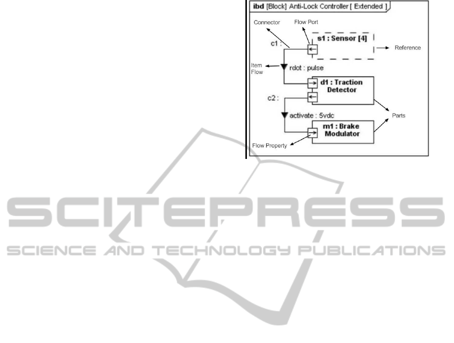
The definition of an Internal Block diagram (IBD)
is based on the UML Composite Structure diagram,
with constraints and extensions as defined by SysML
(OMG-SysML, 2010). SysML Internal Block Dia-
gram (see Fig. 1 for an example) captures the internal
structure of a block in terms of properties and connec-
tors among properties. SysML specification describes
four general categories of block properties: parts, ref-
erences, value properties, and constraint properties.
A part belonging to a block may be of a defined
Figure 1: Example of Internal Block Diagram (IBD).
type or of type of another block. A part defines a local
usage of its defining block within the specific context
to which the part belongs.
A property can represent a role or usage in the
context of its enclosing block. A property has a type
that supplies its definition. A property typed by a
SysML Block that has a composite aggregation is
classified as a part property, except for the special case
of a constraint property. A property that has a Block
as a type and does not have a composite aggregation
is classified as a reference property. A property typed
by a SysML ValueType is classified as a value prop-
erty, and always has a composite aggregation. A part
property holds instances that belong to a larger whole.
Ports are points at which external entities can con-
nect to and interact with a block in different or more
limited ways than connecting directly to the block it-
self. Connections between ports are named Connec-
tors. The type of the port is a block (or one of its
specializations) that also has ports. Standard Ports are
particularly geared towards service-based interactions
by representing interfaces (e.g., software methods)
that are provided or required by a particular block.
A Flow Port describes an interaction point through
which inputs and/or outputs of items, such as data, en-
ergy, or any material, may flow in and out of a block.
Type of a flow property defined in a flow port specifies
what can flow through such a port. Items that actually
flow must be defined by associating an Item Flow to
a SysML Connector (the connection between the flow
ports).
Item flows specify what flows between blocks
and/or parts and across associations or connectors.
Whereas flow properties specify what can flow in or
out of a block, item flows specify what does flow be-
tween blocks and/or parts in a particular usage con-
text. This important distinction enable blocks to be
interconnected in different ways depending on its us-
AModel-drivenApproachtoTransformSysMLInternalBlockDiagramstoUMLActivityDiagrams
93

age context.
3 MAPPING BETWEEN SYSML
INTERNAL BLOCKS DIAGRAM
AND UML ACTIVITY
DIAGRAM
Transformation is proposed after analyzing the
SysML Internal Block Diagram and understanding
that there exists a flow of information between the
parts that composes the main block or between parts
and the main block. The hypothesis is that, by us-
ing parts, the main block and its flows, it is possible
to create a semi-automatic transformation that gener-
ates a UML Activity diagram from a SysML Inter-
nal Block diagram preserving all information. The
transformation is based on the identification of input
and output information that flows from ports and flow
properties defined in ports. Therefore, it is possible to
define an information flow between each block of an
Internal Block diagram and transform it into a UML
Activity diagram.
Guidelines to perform the transformation from
SysML Internal Block Diagram to UML Activity Di-
agram are presented as follows.
• G1 - The main block of an IBD, which internal
structure is presented, is transformed into an ac-
tivity of a UML Activity Diagram;
• G2 - Each part of an IBD is transformed into an
action of the Activity Diagram;
• G3 - Each reference of an IBD is also transformed
into an action of the Activity Diagram;
• G4 - Input and output ports defined in the main
block of IBD are transformed into ActivityPa-
rameterNodes and are considered initial and final
states, respectively;
• G5 - Each port linked to each part/reference
is transformed into InputPin or OutputPin and
linked to corresponding action on the Activity Di-
agram. The condition to transform the port into
InputPin or OutputPin depends of the FlowProp-
erty related to the port.
Actions are connected by using the Pins and the
Connectors in accordance with existing connections
between parts or references of the SysML Internal
Block diagram. If there exists a connection between
an Output port of a part/reference and an Input port of
another part/reference, then there exists a connection
between an Output Pin of an action one and the In-
put Pin of an action two. In some cases, there occurs
the relation between Pins, output or input, and Ac-
tivityParameterNodes. For these cases, the following
guidelines are proposed:
• G6 - Transform the connector that joins parts/ref-
erences in connectors that connect actions in Ac-
tivity Diagram.
• G7 - If the main block has ports, transformed into
ActivityParameterNode, connect ActivityParam-
eterNodes in its action in the Activity Diagram
in accordance with the connections between the
ports of main block and parts/references.
Proposed mapping between SysML Internal
Block Diagram and UML Activity Diagram is pre-
sented in Figure 2. In the Figure, it is possible to
observe which elements of the Activity diagram are
generated automatically from the Internal Block dia-
gram. This mapping and the proposed guidelines are
used to create the transformation, as described in the
following section.
4 PROPOSED ATL
TRANSFORMATION
ATL is chosen as the language for implementing the
transformation from SysML Internal Block diagrams
to UML Activity diagrams. Helpers of ATL can
be seen as methods in an object-oriented program-
ming language. These helpers are used to define ATL
source code which can be called in different parts of
the transformation, even inside other helpers.
Some of the implemented helpers are relatively
simple. Their purpose is to retrieve a set of specific
elements from diagrams. One example of this type
of helper is the AllINFlowPorts Helper (Listing 1),
which purpose is to search for all input ports of all
blocks in an Internal Block diagram. Such a Helper
(Listing 1) is created to aid the isINPort Helper (List-
ing 1), which is created to verify if a specific port,
passed as parameter, is an input port.
The isINPort Helper is used in the transforma-
tion rule INPort2InputPin (Table 2). This helper is
necessary to verify if a port is an input port to be
transformed into an InputPin of the corresponding ac-
tion. In the proposed transformation, for each created
Helper to deal with input ports (Listing 1), a similar
Helper is created to deal with output ports.
Listing 1: Helpers ATL AllInFlowPorts and isINPort.
helper def : AllINFlowPorts : Set (IBD ! FlowPort
) =
IBD ! FlowPort −>a l l I n s t a n c e s ( )−>
s e l e c t ( e | e . d i r e c t i o n . to St r in g ( ) .
equals ( ’ in ’ ) ) ;
ICEIS2015-17thInternationalConferenceonEnterpriseInformationSystems
94
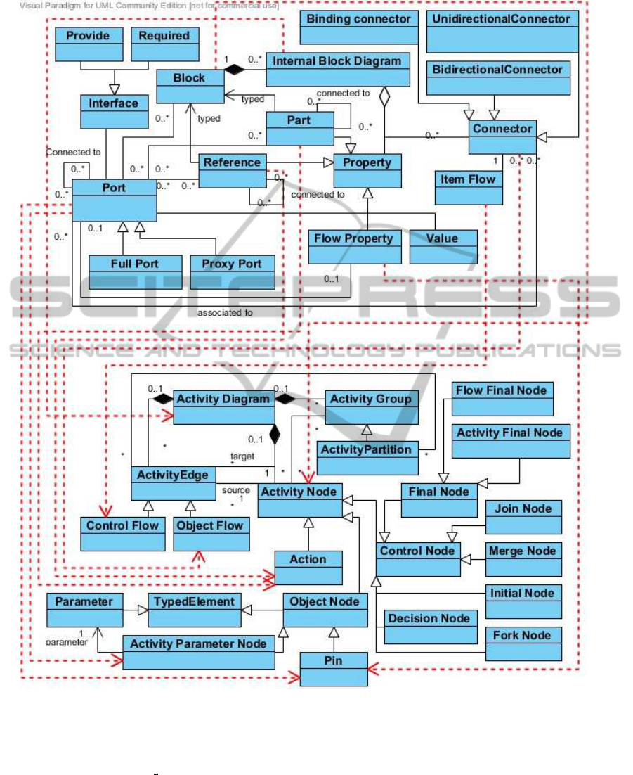
Figure 2: Mapping from SysML Internal Block Diagram to UML Activity Diagram.
helper def : isINP or t (p :IBD ! Por t ) : Boolean =
i f thisModule . AllINFlowPorts −>
s e l e c t ( e | e . b as e
Po rt = p ) . si z e ( ) >
0
then
t r u e
e l se
f a l s e
endif ;
In addition, we created Helpers to search for in-
formation of elements in the Activity diagram that
is being created. Examples are Helpers getAllInput-
Pin and getInputPin (Listing 2). These Helpers are
necessary to retrieve the element InputPin which is
generated from a specific port, passed as parameter.
These Helpers are necessary for the transformation
rule Connector2Edge (Table 2). For this rule, it is nec-
essary the information of source and target of the con-
nections between actions from the Activity diagram.
These relations are transformed from connectors of
AModel-drivenApproachtoTransformSysMLInternalBlockDiagramstoUMLActivityDiagrams
95

Table 1: Rules created in ATL.
Rules Descric¸˜ao
Model2Model Transforms an IBD SysML model to a UML Activity diagram model
MainBlock2Activity Transforms the first found block (Main Block) into the main Activity of the
Activity diagram
Part2Action Transforms attributes that represents parts into Actions of the Activity diagram
Port2ActivityParameterNode Transforms ports of the main block into ActivityParameterNode
INPort2InputPin Transforms input ports of each part into InputPin associated to part
OUTPort2OutputPin Transforms output ports of each part into OutputPin associated to part
Connector2Edge Transforms connectors of the Internal Block into ObjectFlow of the Activity
diagram
the Internal Block diagram. In a similar manner, for
each rule created to deal with the InputPin element, a
similar rule is created to deal with the OutputPin ele-
ment.
Listing 2: Helpers ATL getAllInputPin and getInputPin.
helper def : ge tAl lIn pu t Pi n ( ) : Set (ACT!
InputP i n )=
ACT! InputPin −>a l l I n s t a n c e s ( ) ;
helper def : ge tIn pu t Pi n (p :IBD ! FlowPort ) :ACT!
InputP i n =
thisModule . get A ll I np utP in ()−>
s e l e c t ( c | c . name = p . name + ’: ’+ p .
type . name ) . f i r s t () ;
Helper getPortsByConnector (Listing 3) searches
for all ports related to parts through information pre-
sented in the connectors. This search is necessary due
to the fact that the information of ports are related to
a generic block. If two parts have the same type, in-
formation of ports of such parts is related to generic
blocks used as type of the parts, not to the specific
part. It is not possible, directly, to know what ports
belong to one part.
Listing 3: Helper ATL getPortsByConnector.
helper def : getPortsByConnector ( b : IBD !
Proper t y ) : Set (IBD ! P ort ) =
IBD ! Connector −> a l l I n s t a n c e s ( )−> i t e r a t e ( i
; re s : Set (IBD ! P o rt ) = Set {} |
i f i . end . f i r s t ( ) . partWithP o r t = b then
re s . i ncl u di ng ( i . end . f i r s t ( ) . r o l e )
e l se
i f
i . end . l a s t ( ) . partWithP o r t = b
then
re s . in clu di n g ( i . end . l a s t ( ) . r o l e )
e l s e
re s
endif
endif
) ;
In the transformation of Part to Pin, it is necessary
to know which ports are used by each part. This infor-
mation is only obtained by the identification of ports
used by a connector to perform the connection among
parts. If the connector connects a part one with a part
two, this connection is performed using two specific
ports. Then, using the connector, it is possible to map
which ports belong to each part and perform the trans-
formation of Port2Pin, using Helper getPortsByCon-
nector presented in Listing 3.
Rules are used to specify transformations in which
one source element is transformed into a target ele-
ment. Helpers are applied to aid transformations per-
formed by rules. There are two types of rules. Rules
are called automatically by the ATL language. Lazy
Rules are also rules, but their purpose is to be called
by other rules, creating a cascade effect. For the trans-
formation from an Internal Block diagram to an Ac-
tivity diagram, seven rules are created (one rule and
six lazy rules).
Listing 4: Lazy Rule ATL INPort2InputPin.
lazy rule I NPort2Inp u tP in {
from
i : IBD ! P ort
to
a : ACT! In p ut P in (
name <− i . name + ’: ’+ i . type . name ,
upper <− i . upper ,
lower <− i . lower
)
}
By taking into account the seven rules, some are
used to create direct transformations, such as the lazy
rule INPort2InputPin, presented in Listing 4. This
rule transforms an input port of a specific Block into
an InputPin of an Action, and is a direct transforma-
tion. Each port is transformed into an InputPin that
has the same name and the same values of upper and
lower values of the port. The logic to select the right
port for transformation is realized in another rule, the
lazy rule Part2Action, explained below.
Listing 5: Lazy Rule Part2Action.
lazy rule P ar t2 A ct i o n {
from
i :IBD! P roperty
to
a :ACT! OpaqueAction (
name <− i . name + ’: ’+ i . type . name ,
inputValue <− thisModule .
getPortsByConnector ( i )−>
ICEIS2015-17thInternationalConferenceonEnterpriseInformationSystems
96
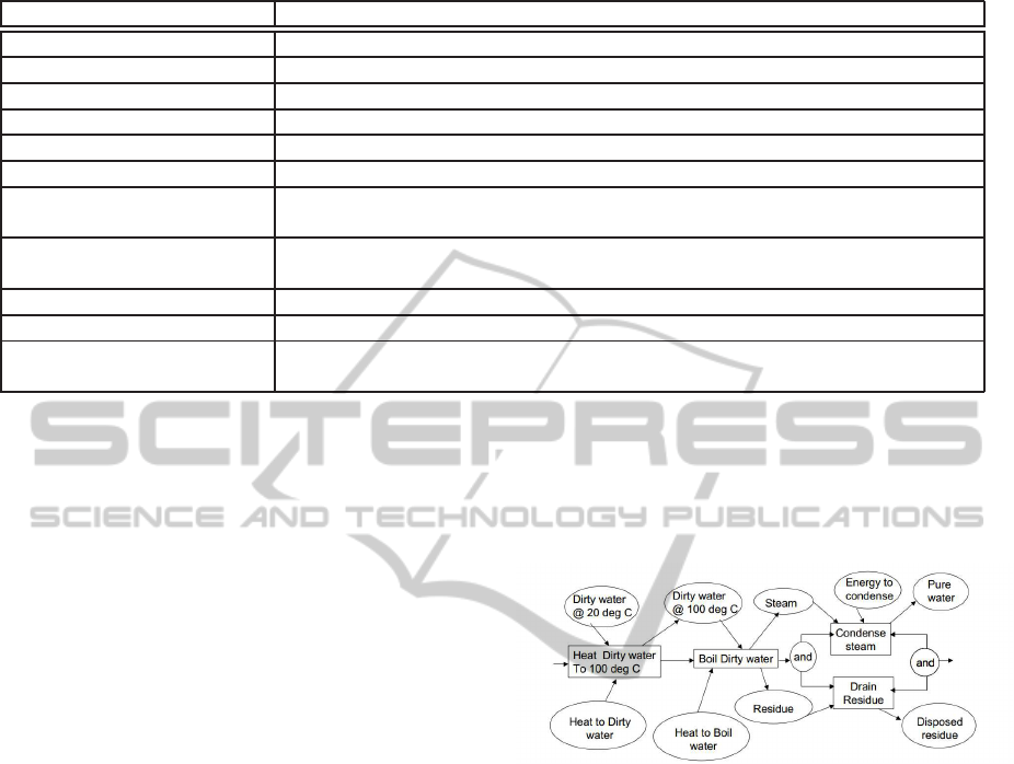
Table 2: Helpers created in ATL.
Rules Description
AllINFlowPorts Searches in the Internal Block for all data input ports from all blocks
AllOUTFlowPorts Searches in the Internal Block for all data output ports from all blocks
isINPort Verifies if a specific port, passed as parameter, is a data input port
isOUTPort Verifies if a specific port, passed as parameter, is a data output port
getAllInputPin Searches in the Activity diagram for all InputPins already transformed
getAllOutputPin Searches in the Activity diagram for all OutputPins already transformed
getAllActivityParameterNode Searches in the Activity diagram for all ActivityParameterNodes already trans-
formed
getActivityParameterNode Gets the ActivityParameterNode generated by transforming a “p” port passed
as parameter
getInputPin Gets the InputPin generated by transforming a “p” port passed as parameter
getOutputPin Gets the OutputPin generated by transforming a “p” port passed as parameter
getPortsByConnector Searches for all ports related to a part through information contained in the
connectors
s e l e c t ( p | thisModule . isI N Port ( p ) )
−>
c o l l e c t ( e | thisModule .
INPo r t 2 In pu tP in ( e ) ) ,
outputValue <− thisModule .
getPortsByCon nector ( i )−>
s e l e c t ( p | thisModule . isOUTPort (p )
)−>
c o l l e c t ( e | thisModule .
OUTPort2OutputPin ( e ) )
)
}
Lazy rule Part2Action (Listing 5) is a rule with
the purpose of generating Actions from parts of an
Internal Block diagram. This rule needs a detailed
analysis of the involved elements in order to gener-
ate Actions from parts of the Internal Block diagram.
Three Helpers are used to create this rule: getPorts-
ByConnector, isINPort and isOUTPort. After select-
ing the input and output ports, lazy rules are called
to transform these ports into InputPin or OutputPin,
respectively. In order to generate InputPins, the IN-
Port2InputPin rule is called.
These proposed rules are applied in a case study
described in the following section.
5 CASE STUDY: WATER
DISTILLER PROBLEM
A case study is described in this section with the main
objective of applying the proposed transformation ap-
proach. The selected diagram is the SysML Internal
Block diagram created for the water distiller problem.
This real-world problem is proposed by the SysML
Team and its solution presented in (Friedenthal et al.,
2008), in Chapter 16. This case study is chosen in
this paper because it is available on the official web-
sites of SysML. The diagram also has an important
requirement, which is to have a well-defined flow of
an element, characteristic required for the generated
Activity diagram to keep the information of the origi-
nal diagram.
Figure 3: Bahaviour of the water Distiller system.
The system for purifying dirty water is described
as follows. A crude behavior diagram is depicted in
Figure 3:
• Heat dirty water and condense steam are per-
formed by a Counter Flow Heat Exchanger;
• Boil dirty water is performed by a Boiler;
• Drain residue is performed by a Drain;
• Water has properties: vol = 1 liter, density 1
gm/cm3, temp 20 C, specific heat 1cal/gm C, heat
of vaporization 540 cal/gm.
SysML Internal Block diagram shows the inter-
nal structure of the Distiller block with an additional
element, feed of the Valve type. Distiller block is
composed of four parts: hx1 (HeatExchange), feed
(Valve), BX1 (Boiler) and drain (Valve), as illustrated
in Figure 4. The SysML Internal Block diagram gen-
erated by the SysML Team shows how these parts
are connected, what are the inputs and outputs of the
AModel-drivenApproachtoTransformSysMLInternalBlockDiagramstoUMLActivityDiagrams
97
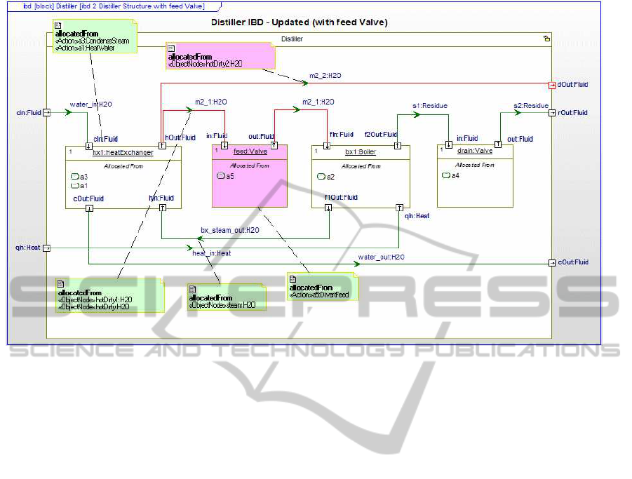
Figure 4: The Water Distiller SysML Internal Block Diagram (Friedenthal et al., 2009).
blocks (parts) involved and the flow of information
between parts that compose the distiller.
For the modeling purposes we used Papyrus, in-
tegrated to the TopCased tool. The TopCased tool
is also used for programming and implementing the
transformation in ATL.
As an input of the transformation, it is necessary
that SysML Internal Block diagram distiller is in a file
with extension XMI (XML Metadata Interchange, an
OMG standard for exchanging metadata information
via XML). This XMI file is interpreted by the trans-
formation that executes rules already defined, gener-
ating the resulting diagram, in our case generating the
equivalent Activity Diagram. The Activity diagram is
generated as a file with extension XMI and has to be
imported by a tool to be displayed graphically. Pa-
pyrus tool, used to modelling the input diagram, ex-
port this input diagram as XMI format, necessary for
the execution of the transformation. However,the tool
does not have the functionality to import the resulting
diagram. This result is discussed in the next section.
6 DISCUSSION AND RESULTS
The proposed transformation is interesting due to two
facts. First, it transforms a structural diagram to a sys-
tem behaviour diagram. Second, the transformation
of a SysML diagram, which is the focus of systems
engineers, to a UML diagram, which is the focus of
software engineers and developers.
The transformation can not be fully automated,
i.e., there is not a one-to-one correspondence between
the involved elements of both diagrams. This is be-
cause the input diagrams for the transformation must
necessarily be SysML Internal Block Diagrams that
have well-defined elements, including a start element
(input ports), an end element (output), and data flows
among the blocks (parts) indicating begin and end
of flow. There are also certain elements present in
SysML Internal Block Diagrams, as representation
of provided and required interfaces between blocks
and simple connectors (without information of flow),
which do not represent a flow of information and do
not have enough relevance to present an Activity di-
agram, in which actions and information of flow ac-
tions are important.
In addition, there is a well-defined flow of data,
but there is no well-defined start and end points to
the flow. When a well-defined flow does exist, but
input and output points are not defined, the transfor-
mation is performed in a semi-automatic way. In this
case, system engineers shall point where the start and
the end of the flow in the Activity diagram is gen-
erated. Due to these issues, an interesting challenge
is to identify SysML Internal Block Diagrams that
could be transformed into UML Activity Diagrams,
and which of these transformationsproduce UML Ac-
tivity Diagrams with satisfactory information.
A problem generated by the used tool is the pro-
ICEIS2015-17thInternationalConferenceonEnterpriseInformationSystems
98
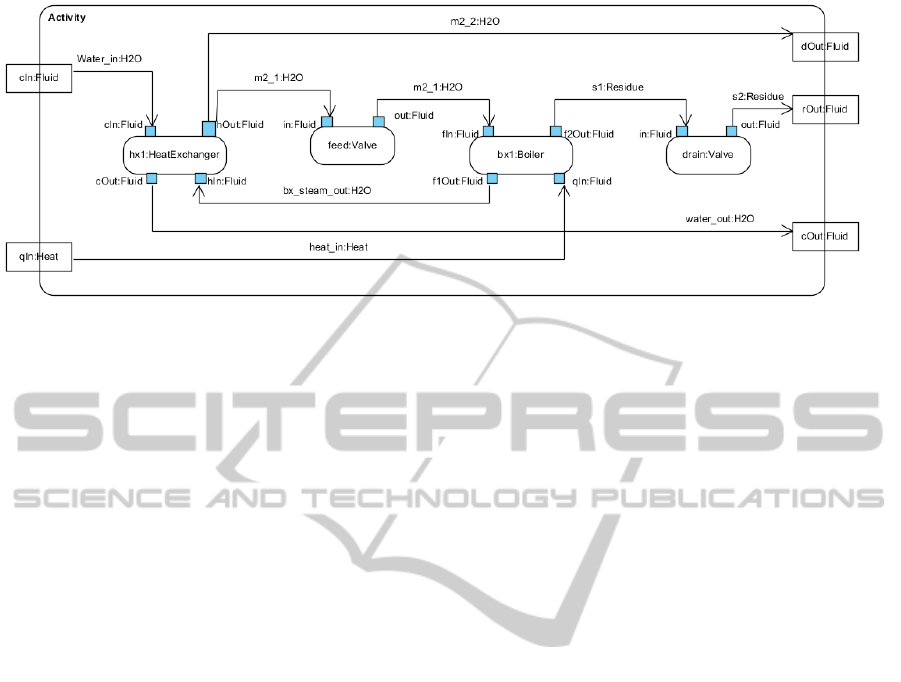
Figure 5: Water Distiller Activity Diagram generated semi-automatically.
cessing of the resulting XMI diagram file automati-
cally in a graphical form. Papyrus, the tool used, al-
lows the user to export the input diagram generated
in the graphical form to a file with extension XMI
(or UML), necessary to perform the transformation.
However, the tool does not allow the user to open
graphically the generated diagram (file with extension
XMI) in an automatic way, making the opening pro-
cess of the resulting diagram fully manual. This issue
can be solved using a tool that allows the user to im-
port files in a XMI extension and generate the graphi-
cal diagram automatically. This issue is not severe, as
this functionality is common in commercial tools.
7 RELATED WORKS
Although ATL has been applied in many
projects, as described in the official website
(https://eclipse.org/atl/), model-driven approaches
transforming SysML diagrams using ATL are not
frequent in the literature. One possible reason is
because of the novelty of SysML. A brief description
of some works is given in this section.
In (Foures et al., 2011), the authors created a
transformationfrom SysML Activity Diagram to Petri
Nets. This is a similar transformation as proposed by
other authors, such as from UML Activity diagrams to
Petri nets (Staines, 2008) (Chang et al., 2014). Trans-
formation described in (Foures et al., 2011) allows the
possibility of reusing other existing transformations,
such as from Petri Nets to VHDL-AMS (Albert et al.,
2005), to simulate the whole model.
Transformations from SysML Activity Diagram
to Petri Nets and from Petri Nets to VHDL-AMS
models are presented in (Foures et al., 2012). Ac-
cording to the authors, the addition of these two ap-
proaches allows the validation of the discrete and con-
tinuous parts of the SysML Activity Diagrams, as
Petri nets can be formally verified and simulated in
a computer tool.
In (Lasalle et al., 2011), the authors created a
transformation from SysML diagrams to UML dia-
grams. Their objective was to generate test cases au-
tomatically from SysML4MBT, a subset of SysML
diagrams for SysML-based tests. The SysML4MBT
is composed of one Block Definition Diagram, one
Internal Block Diagram, one or more State-machine
diagram and one Requirement diagram.
In (Bouquet et al., 2012), the authors propose
an approach to transform SysML Block diagrams,
SysML Internal Block diagrams and SysML Para-
metric diagram for VHDL-AMS code, with the ob-
jective of transferring SysML models for simulation
environments for conducting formal verification. In
(Qamar et al., 2009), the authors perform the trans-
formation between SysML Block diagrams to Mat-
lab/Simulink models in order to simulate continuous
behaviors expressed in SysML in the specific area
of Matlab/Simulink. In (McGinnis and Ustun, 2009)
and (Batarseh and McGinnis, 2012), authors proposed
transformationsfrom SysML diagrams to Arena mod-
els using ATL. According to the authors, the transfor-
mation is useful for verification and validation activ-
ities, and also to facilitate system changes and exten-
sions.
In (Hammad et al., 2013) and (Berrani et al.,
2013), the authors propose a transformation from a
subset of SysML diagrams to Modelica code. The ob-
jective is to develop a method to model and validate
properties, such as energy consumption, in wireless
sensor networks. The method aims to combine the
benefits and facilities of the SysML language with the
possibility of simulation and validation of properties
offered by the Modelica language.
In comparison with other works, the contribution
of this research is to transform one specific SysML
AModel-drivenApproachtoTransformSysMLInternalBlockDiagramstoUMLActivityDiagrams
99

diagram, the Internal Block, to one specific UML di-
agram, the Activity diagram. Instead of using multi-
ple diagrams, such as the works described in (Lasalle
et al., 2011) and (Bouquet et al., 2012), we propose to
create a 1:1 mapping, from one SysML to one UML
diagram. Therefore, other engineers, such as me-
chanical or systems engineers, can effectively work
together with software engineers to design complex
engineering systems, using complementary languages
based on the same metametamodel.
Unlike other researches, such as (Foures et al.,
2012), (Hammad et al., 2013) and (Berrani et al.,
2013), which did transformations from languages
with unrelated semantics, in this paper we propose to
transform modeling languages with the same root, as
UML and SysML both conform to OMG MOF. From
the practical point of view, this is important in indus-
try, as it demands less training efforts, and makes it
more simple to include a new modeling language in
the development process of a company.
Another important objective of this paper is to
propose a mapping of metamodels to describe the
relationship between the SysML Internal Block dia-
gram and the UML Activity diagram, which was not
described in the SysML specification (OMG-SysML,
2010) or in other articles. After this, the other objec-
tive is to implement this relationship using a model-
driven approach. A semi-automatic transformation
using the ATL language is performed based on the
described mapping of metamodels.
8 CONCLUSIONS
A mapping between metamodels and further imple-
mentation using ATL for transforming SysML Inter-
nal Block models to UML Activity models is pre-
sented in this paper. Then, we applied our proposal
in a case study described by the team responsible to
create SysML. This case study is chosen in this pa-
per because it is available on the official websites of
SysML, which makes it possible for other researchers
to read the description of the problem and its require-
ments.
The focus of this paper is to facilitate works per-
formed by systems engineers, with SysML modeling,
and software engineers, with UML modeling. Then,
software systems are designed both from the systems
point of view and the software point of view. There-
fore, a team of engineers can effectively work to-
gether in order to design complex engineering sys-
tems, using complementary languages based on the
same metametamodel.
The limitation of the transformation is that it can
not be fully automated. System engineers shall point
where the start and the end of flow in the Activity di-
agram is generated. However, this is the only draw-
back, and it is not considered severe.
An interesting result is that further transforma-
tions can be performed using ATL, as already de-
scribed in the literature and in Section 7. For instance,
from the generated UML Activity diagram, the de-
veloper can propose other transformations, such as
model-to-code, or even from the Activity diagram to a
formal model, such as Petri nets. Therefore, the initial
model, designed using the SysML Internal Block dia-
gram can be simulated and verified after a set of trans-
formations. A complete methodology, from struc-
tural design to process design and further transforma-
tions to code or formal verification can be performed.
These are activities to be executed in future works.
ACKNOWLEDGEMENTS
We would like to thank the Brazilian research agen-
cies CNPq (grant 445500/2014-0) and CAPES/-
FAPITEC (grant AUXPE 0517/2014) for supporting
this work.
REFERENCES
Albert, V., Nketsa, A., and Pascal, J. (2005). Towards a
metalmodel based approach for hierarchical petri net
transformations to vhdl. In European Simulation and
Modelling Conference, Porto.
Andr´e, C., Mallet, F., and de Simone, R. (2007). Model-
ing Time(s). In Proc. of the 10th International Con-
ference on Model Driven Engineering Languages and
Systems), pages 559–573.
Batarseh, O. and McGinnis, L. F. (2012). System Modeling
in SysML and System Analysis in Arena. In Proc.
of the Winter Simulation Conference, WSC ’12, pages
1–12.
Berrani, S., Hammad, A., and Mountassir, H. (2013). Map-
ping sysml to modelica to validate wireless sensor net-
works non-functional requirements. In Programming
and Systems (ISPS), 2013 11th International Sympo-
sium on, pages 177–186.
Bezivin, J. (2006). Model Driven Engineering: An Emerg-
ing Technical Space. In Lammel, R., Saraiva, J.,
and Visser, J., editors, Generative and Transforma-
tional Techniques in Software Engineering, volume
4143 of Lecture Notes in Computer Science, pages
36–64. Springer Berlin Heidelberg.
Bouquet, F., Gauthier, J., Hammad, A., and Peureux, F.
(2012). Transformation of SysML Structure Diagrams
to VHDL-AMS. In 2012 Second Workshop on Design,
Control and Software Implementation for Distributed
MEMS, pages 74–81.
ICEIS2015-17thInternationalConferenceonEnterpriseInformationSystems
100

Chang, X., Huang, L., Hu, J., Li, C., and Cao, B. (2014).
Transformation from Activity Diagrams with Time
Properties to Timed Coloured Petri Nets. In IEEE 38th
Annual Computer Software and Applications Confer-
ence, pages 267–272.
da Silva Melo, M. and Soares, M. S. (2014). Model-Driven
Structural Design of Software-intensive Systems Us-
ing SysML Blocks and UML Classes. In ICEIS 2014
- Proceedings of the 16th International Conference
on Enterprise Information Systems, Volume 2, pages
193–200.
Foures, D., Albert, V., and C., P. J. (2011). Activitydia-
gram2petrinet: Transformation-based model in accor-
dance with the omg sysml specifications. In Eurosis,
The 2011 European Simulation and Modelling Con-
ference, France.
Foures, D., Albert, V., Pascal, J.-C., and Nketsa, A. (2012).
Automation of sysml activity diagram simulation with
model-driven engineering approach. In Proceedings
of the 2012 Symposium on Theory of Modeling and
Simulation - DEVS Integrative M&S Symposium, TM-
S/DEVS ’12, pages 11:1–11:6, San Diego, CA, USA.
Society for Computer Simulation International.
France, R. B., Ghosh, S., Dinh-Trong, T., and Solberg, A.
(2006). Model-Driven Development Using UML 2.0:
Promises and Pitfalls. Computer, 39:59–66.
Friedenthal, S., Moore, A., and Steiner, R. (2008). A Prac-
tical Guide to SysML: Systems Modeling Language.
Morgan Kaufmann Publishers Inc., San Francisco,
CA, USA.
Friedenthal, S., Moore, A., and Steiner, R. (2009).
OMG Systems Modeling Language Tutorial, available
at http://www.omgsysml.org/INCOSE-OMGSysML-
Tutorial-Final-090901.pdf .
Goknil, A., Kurtev, I., and Berg, K. V. D. (2014). Gener-
ation and Validation of Traces between Requirements
and Architecture based on Formal Trace Semantics.
Journal of Systems and Software, 88(0):112–137.
Hammad, A., Mountassir, H., and Chouali, S. (2013). An
approach combining sysml and modelica for mod-
elling and validate wireless sensor networks. In Pro-
ceedings of the First International Workshop on Soft-
ware Engineering for Systems-of-Systems, SESoS ’13,
pages 5–12, New York, NY, USA. ACM.
Jiang, L., Eberlein, A., Far, B. H., and Mousavi, M. (2008).
A Methodology for the Selection of Requirements En-
gineering Techniques. Software and System Modeling,
7(3):303–328.
Jouault, F. and Kurtev, I. (2005). Transforming Models with
ATL. In MoDELS Satellite Events, pages 128–138.
Kim, S.-K., Myers, T., Wendland, M.-F., and Lindsay,
P. A. (2012). Execution of Natural Language Re-
quirements using State Machines Synthesised from
Behavior Trees. Journal of Systems and Software,
85(11):2652–2664.
Lasalle, J., Bouquet, F., Legeard, B., and Peureux, F.
(2011). SysML to UML Model Transformation for
Test Generation Purpose. SIGSOFT Softw. Eng. Notes,
36(1):1–8.
McGinnis, L. and Ustun, V. (2009). A simple example of
sysml-driven simulation. In Simulation Conference
(WSC), Proceedings of the 2009 Winter, pages 1703–
1710.
OMG-SysML (2010). Systems Modeling Language
(SysML) - Version 1.2.
OMG-UML (2010). Unified Modeling Language (UML):
Superstructure - version 2.3.
Qamar, A., During, C., and Wikander, J. (2009). Designing
Mechatronic Systems, aModel-Based Perspective, An
Attempt to Achieve SysML-Matlab/Simulink Model
Integration. In IEEE/ASME International Conference
on Advanced Intelligent Mechatronics, pages 1306–
1311.
Soares, M. S., Julia, S., and Vrancken, J. L. M. (2008).
Real-time Scheduling of Batch Systems using Petri
Nets and Linear Logic. Journal of Systems and Soft-
ware, 81(11):1983–1996.
Soares, M. S., Vrancken, J. L. M., and Verbraeck, A.
(2011). User Requirements Modeling and Analysis of
Software-Intensive Systems. Journal of Systems and
Software, 84(2):328–339.
Staines, T. (2008). Intuitive Mapping of UML 2 Activity
Diagrams into Fundamental Modeling Concept Petri
Net Diagrams and Colored Petri Nets. In 15th Annual
IEEE International Conference and Workshop on the
Engineering of Computer Based Systems, pages 191–
200.
AModel-drivenApproachtoTransformSysMLInternalBlockDiagramstoUMLActivityDiagrams
101
