
Evaluating HCI Design with Interaction Modeling and Mockups
A Case Study
Adriana Lopes
1
, Anna Beatriz Marques
1
, Simone Diniz Junqueira Barbosa
2
and Tayana Conte
1
1
USES Research Group, Instituto de Computação, Universidade Federal do Amazonas, Manaus, Brazil
2
Semiotic Engineering Reseach Group, Departamento de Informática, PUC-Rio, Rio de Janeiro, RJ, Brazil
Keywords: User Interface, Interaction Design, Interaction Modeling.
Abstract: Interactive systems are increasingly present in daily life, but many people still face difficulties to use them.
We believe that using models and artifacts to represent the interaction in a systematic way during systems
design may prevent such difficulties. In this paper, we investigate the combined use of MoLIC, an
interaction modeling language, with user interface mockups. While both artifacts are supposed to promote
the understanding of user goals and the designer’s reflection on alternative solutions and decisions regarding
the interaction, we have not found evidence of their usage impacts on quality. Thus, this paper presents an
experimental study on the joint usage of MoLIC interaction diagrams and mockups during systems design,
aiming both to identify participants’ perceptions on the joint use of the two artifacts and to analyze the
quality of the generated artifacts by observing which types of defects would occur. The results show that,
although some participants found that MoLIC diagrams were not very easy to build, most participants
considered the creation of mockups based on MoLIC diagrams useful. In addition, the number of defects
found in the MoLIC diagrams points to the need of developing techniques to evaluate the artifact before
proceeding with the design process.
1 INTRODUCTION
The software industry is interested in offering users
high-quality interactive experiences, so users will
not have problems with interactive systems. To
Puerta (1997), one way to reduce problems is by
employing an interaction model during system
development, because it describes the behavior of
both user and system during the interaction, thus
allowing the detection of problems early in the
design process.
Paula et al. (2003) devised the MoLIC language
(Modeling Language for Interaction as
Conversation) as an epistemic tool to support
interaction design. MoLIC is grounded in Semiotic
Engineering (De Souza, 2005), a theory of HCI with
particular focus on communication between the
designer
1
and the user mediated by interactive
systems. MoLIC diagrams represent the interaction
1
We use the term designer for the Software Designer, also called
Information Architect, i.e., the professional involved in designing
the interactive solution.
as a metaphor of the conversations that may occur
between the user and the user interface, and
therefore all possible ways of interaction, including
alternative ways to achieve the same goal (Paula et
al., 2003).
Sangiorgi and Barbosa (2009) proposed an
extension of MoLIC to include mockups, which are
sketches of screens to represent the user interface
before the actual development of prototypes. By
doing so, the designer can have an overview of the
application at the level of behavior and of the low-
fidelity appearance of its user interface. To evaluate
their proposal, they conducted a case study on the
combined use of MoLIC diagrams and mockups
during the design of applications. One of the case
study results showed that the interaction and the user
interface cannot be considered fully independent of
each other. Therefore, the combined use of MoLIC
and mockups promotes a deeper reflection by the
designer on the interaction. However, research on
the impact of using this approach over the quality of
the resulting interaction design was not found, which
brings some questions to mind: What types of
defects can be found in the generated artifacts? How
79
Lopes A., Marques A., Diniz Junqueira Barbosa S. and Conte T..
Evaluating HCI Design with Interaction Modeling and Mockups - A Case Study.
DOI: 10.5220/0005374200790087
In Proceedings of the 17th International Conference on Enterprise Information Systems (ICEIS-2015), pages 79-87
ISBN: 978-989-758-098-7
Copyright
c
2015 SCITEPRESS (Science and Technology Publications, Lda.)

do the designers view the combined use of the
artifacts? Is there an ideal sequence for constructing
the artifacts?
In this paper, we report a study that analyzed the
impact on quality of two variations of combined
usage of MoLIC interaction diagrams and mockups
during interaction design: MoLIC-first or mockups-
first. We investigated the participants’ perceived
ease of use and usefulness of each approach, as well
as some more general opinions. We also analyzed
the quality of the interaction models and mockups
created by the participants, by identifying defects in
the generated artifacts.
The next sections present concepts about
interaction design with MoLIC diagrams and
mockups. Section 3 describes the planning and
execution of the experimental study. In section 4 we
report the quantitative and qualitative analyses of the
study. Finally, we present some concluding remarks
and discuss envisioned future work.
2 INTERACTION DESIGN
Interaction design aims to support people in their
activities using these interactive systems. According
to Semiotic Engineering, the user interface is the
designer’s deputy, i.e., it represents the designer at
interaction time, enabling the mediated designer-to-
user metacommunication about the designer’s view,
her design decisions, and how the user can or should
interact with the system to achieve his goals (de
Souza, 2005). When the user interacts with the
system through the interface, he interprets the
metacommunication message and responds to it to
achieve his goals. MoLIC was created to represent
the metacommunication message, allowing the
designer to reflect on his/her interaction design
solution.
During interaction design, the designer must
attempt to anticipate communication breakdowns
and design ways for the user either to avoid
breakdowns or to restore the communication after
them, so that he can continue using the system to
achieve his goals (Paula et al., 2003).
2.1 Modeling Language for Interaction
as Conversation
MoLIC allows us to represent in diagrams an
application’s apparent behavior, in the sense of how
the designer communicates it and how users
experience it (Sangiorgi and Barbosa, 2009). MoLIC
diagrams represent the interaction as a conversation
between the user and the designer’s deputy, without
detailing the user interface, and allowing designers
to reflect on the interaction alternatives they may
provide to the users (Paula et al., 2003).
To illustrate the MoLIC diagrammatic notation,
Figure 1 represents a hypothetical system for hotel
search, including the basic elements of MoLIC
diagram, according to Sangiorgi and Barbosa
(2009):
a) Scene: a rounded rectangle depicting the
moment in the interaction when it is up to the
user to decide how the conversation should
proceed. The first compartment contains the
topic of the scene and represents the user goal
when interacting with the designer’s deputy at
that particular moment. The second
compartment details the scene, as described
below:
i. Signs: represent the information involved in
the user and deputy utterances. For instance,
in the View all hotels scene, we have the
signs: “name, description, rating and price.”
ii. Utterances: make up the dialogue and
specify who is sending the sign, the user (u:),
the designer’s deputy (d:, used for system
output), or both (d+u:, for user input). In the
View all hotels scene, we have signs uttered
by the designer’s deputy alone (e.g. “d: name,
d: description, d: price”) and signs uttered by
both the designer’s deputy and the user (e.g.
“d+u: rating”).
iii. Dialogues: represent a fragment of the
conversation about a topic, and is composed
by utterances, e.g. “view hotels, view hotels
list, search”.
iv. Dialogue Structures: dialogues can be
composed of other dialogues, according to
some structure represented by the reserved
words SEQ, XOR, OR or AND. In Figure 1,
the dialogue “search hotel” is composed of
dialogues structured with AND, to indicate
that they are all necessary, but they can occur
in any order.
b) User Utterance: a directed line labeled with
“u: content,” e.g “u: search hotel”, depicting
the user’s intent to proceed with the
conversation in a given direction.
c) System Process: a black box depicting the
internal processing of a user request. It is used
only when it is necessary to provide feedback
to the user, otherwise the user will not know
what has happened.
ICEIS2015-17thInternationalConferenceonEnterpriseInformationSystems
80
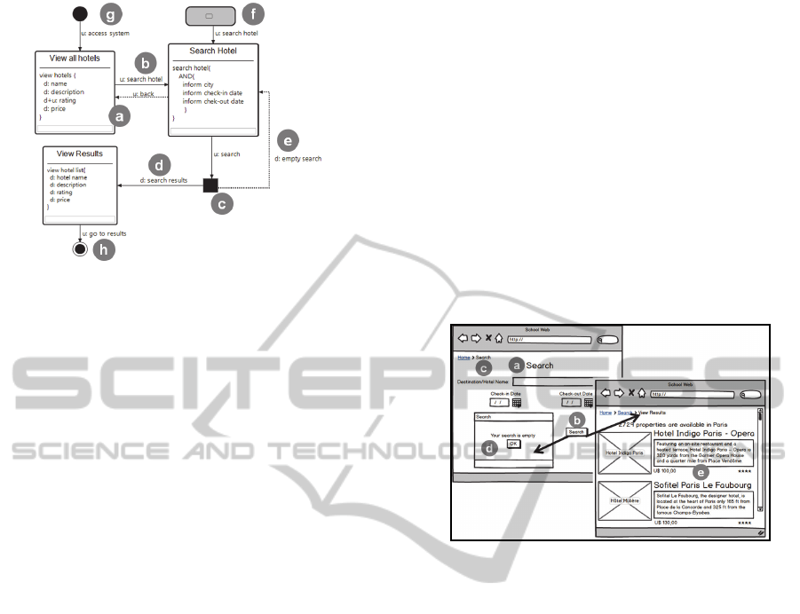
Figure 1: A basic MoLIC diagram.
d) Designer Utterance: a directed line labeled
with “d: content” (e.g. “d: search results”),
depicting a designer’s answer to a user request,
typically given after a system process.
e) Breakdown Recovery Utterance: a dashed
directed line, depicting an utterance to help the
user recover from a communication breakdown
or to allow him to change his mind regarding
his goal. It may be uttered by the designer or by
the user, e.g. “u: back” or “d: empty search”
f) Ubiquitous Access: a gray rounded rectangle
depicting the opportunity for the user to change
the topic of the conversation at any time, to
achieve a goal different from the current one.
g) Opening Point: a filled black circle indicating
where the interaction can start when the user
accesses the system.
h) Closing Point: a black circle within a larger
white circle, representing the end of the
interaction, i.e., when the user leaves the
system.
After defining the structure of the conversation,
we obtain a global view of the interaction between
the user and the designer’s deputy.
2.2 From the Interaction to the User
Interface
After the total or partial definition of the interaction,
the designer starts to design the user interface,
usually through mockups, which are sketches of the
user interface that reflect the needs of the customers
in more concrete terms of presentation (Luna et al.,
2010). Mockups allow representing the components
of the interface and the navigation across different
presentation units (“screens”) of an application.
Barbosa and Silva (2010) present some common
decisions regarding interface design, based on the
elements in a MoLIC interaction diagram. We next
instantiate some decisions made for the interface
design of our hypothetical system, as illustrated in
Figure 2.
a) Scene: mapped onto (parts of) presentation
units, such as screens, windows or pages (e.g.
search hotel scene “Search” page and view
results scene “View Results” page).
b) User Transition Utterances: mapped onto
buttons or links (e.g. utterance “u: search hotel”
“Search” button).
c) Breakdown Recovery Utterance: Also
mapped onto links and buttons at the interface,
so that the user can change the course of the
conversation (e.g. “u: back” “Search” link).
Figure 2: Interaction diagram mapping modeled with
MoLIC for interface design.
d) Designer’s Deputy Utterance: mapped on the
user interface as status and error messages, and
may also change the course of the conversation
(e.g. “d: empty search” feedback about the
data not having been found; and “d: search
results” list of search results).
e) Signs: mapped onto text, images, and input
fields (e.g. “hotel name, description, rating and
price” hotels information in the search
results).
During both the construction of MoLIC diagrams
and the mapping of the interaction diagram onto
mockups, defects can be included from any
misunderstanding or mistransformation of
information, as occurs in other stages of interactive
systems development. To investigate the types of
defects that can be found in these artifacts and thus
contribute to their quality in interaction systems
design, we conducted a case study, described next.
3 CASE STUDY
We analyzed two design approaches based on the
EvaluatingHCIDesignwithInteractionModelingandMockups-ACaseStudy
81
joint use of MoLIC diagrams and mockups: (1)
elaborating mockups based on the MoLIC diagram
of an interaction scenario; and (2) creating the
MoLIC diagram based on mockups. The study also
aimed to obtain evidence about the benefits and
drawbacks of these two interaction design
approaches. This section describes the study
planning and implementation.
3.1 Case Study Planning
We defined the goal of the study according to the
Goal-Question-Method (GQM) paradigm (Basili and
Rombach, 1988), as shown in Table 1.
Table 1: Experimental study goal.
Analyze
Design approaches based on joint use of
MoLIC diagrams and mockups.
For the purpose of
Characterizing.
With respect to
Quality of the artifacts produced.
Perception about the ease of use.
Perception about usefulness.
From the
viewpoint of
Researchers in HCI.
In the context
HCI design.
Still in the planning, we defined the resources
needed for the implementation of study, as follows:
Environment. Participants used MoLIC Designer
2
for building MoLIC diagrams and Balsamiq
Mockups
3
for building mockups. They were
conducted in an academic environment, where new
technologies are usually tested before being
transferred to industry (Shull et al., 2001).
Input Artifacts. We created the consent forms, two
different interaction scenarios for a problem in the
context of a Web application and, based on that,
MoLIC diagrams and mockups. The group of
participants who received a scenario and a MoLIC
diagram created the corresponding mockups,
whereas the group of participants who received a
scenario and mockups should create the
corresponding MoLIC diagram. Moreover, we
created a post-study questionnaire to collect data on
each participant’s perception on each employed
approach.
Participants. 13 students (undergraduate in the final
year of course in Computer Science and graduate in
Informatics) were selected who had little or no
knowledge about the construction of mockups or
interaction modeling.
2
https://code.google.com/p/molic-designer/
3
https://balsamiq.com/
Training. We provided training on both interaction
modeling using the MoLIC language and user
interface design using mockups.
3.2 Case Study Implementation
The study comprised in two steps, where each group
performed a different activity in the construction
stages of MoLIC diagrams and mockups, as shown
in Table 2. Participants were randomly divided into
two groups, where the undergraduate students are
P1-P4 and the graduate students are P5-P13. Before
the study, everyone signed a Consent Form, agreeing
to make their data available for further analysis.
Table 2: Study groups and steps.
Group Participants 1st Step 2nd Step
A
P3, P4, P7,
P8, P9, P11,
P12
from mockups
to MoLIC
from MoLIC to
mockups
B
P1, P2, P5,
P6, P10, P13
from MoLIC
to mockups
from mockups
to MoLIC
Each participant worked individually, using
computers with the tools installed. Each group
performed the activity separately from the other
groups, taking an average 90 minutes.
4 ANALYSIS OF THE RESULTS
The results of the experimental study were analyzed
from two perspectives, detailed in the next
subsections: (a) the quality of the artifacts produced
based on the analysis of defects; and (b) the
participants’ perception on the usefulness and ease
of use of each approach. To analyze the quality of
the artifacts, a researcher examined the artifacts
produced in step 1 and another researcher examined
the artifacts produced in step 2 in search for defects.
They later gathered for a peer review of defects
found; and discussed the categorization of defects
according to taxonomies of defect types adapted
from Travassos et al. (2001), as presented in Table
3.
Table 3: Defect taxonomy for each artifact (Art.): MoLIC
diagrams (ID) and mockups (M).
Defect
Types
Art. Description
Omission
ID
The omission or negligence of any information
necessary to solve the problem in the interaction
diagram.
M
The omission or negligence of any information
needed for the mockup solution.
ICEIS2015-17thInternationalConferenceonEnterpriseInformationSystems
82
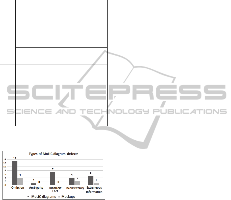
Table 3: Defect taxonomy for each artifact (Art.): MoLIC
diagrams (ID) and mockups (M) (cont.).
Defect
Types
Art. Description
Ambiguity
ID
A poor definition of certain information in the
interaction diagram, which may lead to multiple
interpretations.
M
A poor definition of certain information in a
mockup, which may lead to multiple interpretations.
Incorrect Fact
ID
Misuse of the elements from the interaction
diagram for the interpretation of those involved.
M
Misuse of the interface elements during the
mockup development, allowing an incorrect
interpretation of them.
Inconsistency
ID
Conflicting information between the
elements of the interaction diagram and the
information needed to solve the problem
M
Conflicting information between the
elements of the mockup and the information
needed to solve the problem.
Extraneous
Information
ID
Unnecessary information included in the
interaction diagram.
M
Unnecessary information included in the
mockup.
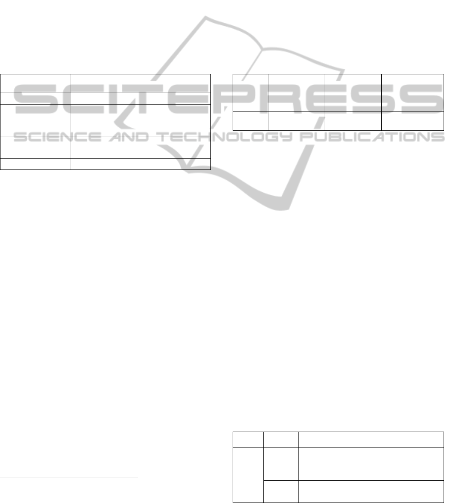
Figure 3 shows the number of defects found in
MoLIC diagrams and in mockups, classified by type,
which are discussed in the next subsections.
Figure 3: Number of defects by type and by artifact.
4.1 Defects in the MoLIC Diagrams
In this subsection we described all defects found in
MoLIC diagrams, for each defect type:
Omission. Regarding the scene element, the main
defect found was not specifying a scene for one or
more user goals detailed in the given scenario. This
means that the participant did not capture all of the
goals that the user could achieve with the system.
Regarding the scene details, participants failed to:
specify dialogues; describe the dialog structures
(XOR, AND, SEQ and OR); indicate the sign issuer
used in the case of (d+u:); and represent some signs
given in the interaction scenario. The transition
element got more omission defects, and of different
types, such as omissions of: utterance (or the
utterance issuer) when switching from one scene to
another; system processing, when some internal
process was necessary to handle the user request;
and breakdown utterance, when breakdown recovery
was necessary after a system process. Some
participants omitted the ubiquitous access (or its
corresponding utterance) and opening point
elements, without which the user interaction with the
system would be quite limited.
Incorrect Fact. Regarding the scene element,
participants used verbs that did not represent the
user goals, but the system goals. Again, most of the
defects in this category were related to the transition
element, for instance: representing the wrong issuer
of a transition utterance after a system process
(using “u:” instead of “d:”), that is, as if the user
were providing a feedback after an internal system
process when, in fact, the designer plays this role; or
after a scene (using “d:” instead of “u:”). In
breakdown recovery utterances, instead of using
dashed lines, participants used solid lines that
represent regular transition utterances. Regarding the
system process, system decisions were not detailed
to represent alternatives of the system, but only a
single possible feedback, without considering that
the system process must provide recovery utterances
for potential communication breakdowns. The
ubiquitous access element was incorrectly used as
the beginning of the user interaction, in place of an
opening point.
Extraneous Information. Some scenes, transition
utterances, and preconditions that were not described
in the interaction scenario were represented in the
mockups. Also, in the scene dialogs, we identified
defects such as the detailing of the issuer preceding
each dialog, although it should precede signs instead
of dialogs. The closing point element was needlessly
represented more than once.
Ambiguity. The only defect found was related to the
use of two user transition utterances for the same
goal, which provided multiple interpretations about
the user transition.
Inconsistency. Regarding the dialogue scenes,
dialogue structures of the MoLIC language (XOR,
AND, SEQ, and OR) were inconsistent with the
scenario (e.g. using AND instead of XOR). The
direction of some transitions were inconsistent with
the sequence of interaction scenes in relation to what
was described in the interaction scenario. Regarding
the signs, some of the sign issuers were attributed to
the user or to the designer’s deputy in a inconsistent
manner with what was described in the interaction
EvaluatingHCIDesignwithInteractionModelingandMockups-ACaseStudy
83

scenario or represented in the mockups (i.e.,
confusion between “d:” and “u:”).
4.2 Defects in the Mockups
From Figure 3, one may notice that the only types of
defects found in the mockups were: Omission,
Inconsistency, and Extraneous Information.
Omission. Some participants did not develop the
mockup representing the main screen described in
the interaction scenario, and the breakdown handling
elements represented in the MoLIC diagram were
not represented in the mockups. Furthermore, not all
signs in the scenes were represented in the mockups,
including required fields, which make the mockups
incomplete and prevent the user to achieve a certain
goal. Some ubiquitous accesses were not mapped,
e.g., onto navigation bars or menu items.
Inconsistency. Some dialogues detailed in the
scenes were mapped onto inconsistent elements in
the mockup that are inconsistent with the dialogues
described in the scene. And some breakdown
utterances were mapped onto the mockups in an
inconsistent way with respect to what was detailed
in the MoLIC diagram.
Extraneous Information. Some pieces of
information in the mockup went beyond the
specification of a scene depicted in the MoLIC
diagram and the interaction scenario.
4.3 Dicussion about Defects in the
MoLIC Diagrams and Mockups
We could observe that there was a greater number of
defects in the MoLIC diagrams than in the mockups.
Moreover, we noticed more difficulties when the
participants had to create the MoLIC diagram. A
possible explanation is that the MoLIC language
notation is less known by the participants and the
mockups are similar to what system users see while
interacting with systems.
For more details about the defects found in the
MoLIC diagrams and mockups, as well as the
severity of each defect, please refer to the technical
report available at (Lopes et al., 2015). To better
understand the participants’ perception about the
approaches used, we analyzed the post-study
questionnaires, as described in the following
subsection.
4.4 Analysis of the Perception about
the Ease of Use and Usefulness of
the Approaches
The post-study questionnaires were prepared based
on the statements of the TAM model (Technology
Acceptance Model), which has been widely applied
to a large set of new technologies (Venkatesh et al.,
2003). According to Laitenberger and Dreyer
(1998), to investigate the acceptance of the users
about a given technology, a model is necessary to
demonstrate people’s attitudes and behaviors.
On the questionnaire we employed a six-point
scale, ranging from totally agree to totally disagree
about the perceived ease of use (E1 to E5, Figure 4)
and perceived usefulness (U1 to U6, Figure 5) of
each approach to the participants answer. As
suggested by Laitenberger and Dreyer (1998), we
did not use an intermediate level because it would
not provide information regarding the inclination
(either positive or negative) of the participants.
E1 – It was easy to learn how to prepare the
artifacts by following this approach to interaction
design.
E2 – I managed to prepare the artifacts following
this approach the way I would like during
interaction design.
E3 – It was easy to gain skill in the elaboration of
the artifacts by following this approach to
interaction design.
E4 – It was easy to remember how to elaborate the
artifacts by following this approach to interaction
design.
E5 – I find it easy to elaborate the artifacts by
following this approach to interaction design.
Figure 4: Post-study questionnaire on ease of use.
Participants also answered open-ended questions,
through which they could cover topics about
difficulties found during the study. Those answers
were important to better understand the quantitative
results obtained from the answers to the statements
of the TAM model.
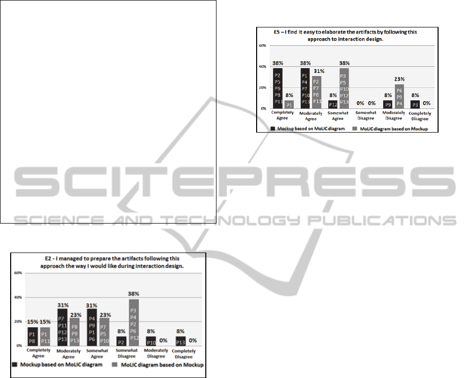
Figure 6 illustrates the results of statement
E2.aAlthough most of the participants have agreed
with statement E2, there was a partial disagreement
of 38% when they built the MoLIC diagram based
on mockups. We highlight the following answers to
the question “I. Which items of the MoLIC diagram
didn’t you identify directly from the mockups (but
only from the interaction scenario)?”:
“The interaction flow was not identified directly from
mockups” (P2)
ICEIS2015-17thInternationalConferenceonEnterpriseInformationSystems
84
“The closing point, which in the case would finalize
the interaction, was not identified directly from the
mockup” (P6)
U1 – Elaborating the artifacts following this
approach facilitated the interaction design.
U2 – I consider this approach useful for interaction
design.
U3 – Elaborating the artifacts following this
approach helped me to understand the process of
interaction design faster.
U4 – Elaborating the artifacts following this
approach improved my performance in the
interaction design.
U5 – Elaborating the artifacts following this
approach increased my productivity in interaction
design (I believe that I have identified more aspects
of interaction in a shorter time than it would take
without using this approach).
U6 – Elaborating the artifacts following this
approach increased my effectiveness in the
interaction design (I believe that I have prepared an
artifact in a more complete way using this approach
than if I had not).
Figure 5: Post-study questionnaire on usefulness.
Figure 6: Answers to E2 – I managed to prepare the
artifacts following this approach the way I would like
during interaction design.
Regarding the creation of the mockups based on the
MoLIC diagram, in response to the question: “II.
Which items from the mockups didn’t you identify
directly from the MoLIC diagram? (but only from
the interaction scenario)?”, we cite:
“I did not identify which fields were required” (P4)
“I did not notice that the login could be done with the
user name, social security number or email” (P12).
Although these participants had agreed about E2
when they had buit mockups, the quotes by P4 and
P12 reflect difficulties to understand the MoLIC
notation: the participants did not understand or did
not remember the meanings of the dialogue
structures (AND, OR, XOR, etc.).
Figure 7 depicts the results of statement E5. We
can notice that the construction approach of
mockups based on MoLIC diagram obtained a
higher level of total agreement, 38% in relation to
the construction of approach of the MoLIC diagram
based on mockups (8%).
Figure 7: Answers to E5 – I find it easy to elaborate the
artifacts by following this approach to interaction design,
regarding ease of use.
However, both approaches showed some indications
of disagreement. To investigate the total
disagreement result of 8% and wide disagreement of
8% in relation to the creation of mockups based on a
MoLIC diagram, we highlight some answers to the
question: “III. What are the difficulties encountered
during the construction of the mockups based on the
MoLIC diagram?”:
“Sometimes I had a doubt whether a particular
interaction is done by the user or by the system “(P5)
“I was not sure about the necessary amount of
mockups, or if it would be possible to represent the
breakdown handlings in the same mockup” (P7)
Regarding the creation of a MoLIC diagram
based on the mockups, 23% of the participants
widely disagreed with E5. In response to the
question “IV. What are the difficulties encountered
during the construction of the MoLIC diagram based
on the mockups?”, we cite:
“It was hard to remember the MoLIC notation” (P6)
“I found it a bit hard to define the user goals on the
scenes, because the user goal is not always the title of the
screen, but this is the impression caused when the
construction is based on the mockup” (P9)
Figure 8 illustrates the results of U2. One may
notice a high level of agreement between the two
approaches. We can also notice that 31% of the
participants disagreed somewhat or moderately that
creating the MoLIC diagram based on mockups is
useful. And only one participant disagreed that
creating mockups based on the diagram is useful for
interaction design.
In the general open question, “V. You can help
us by describing the positive and negative aspects
about the usefulness of this approach to interaction
design, especially if you think that using this
EvaluatingHCIDesignwithInteractionModelingandMockups-ACaseStudy
85
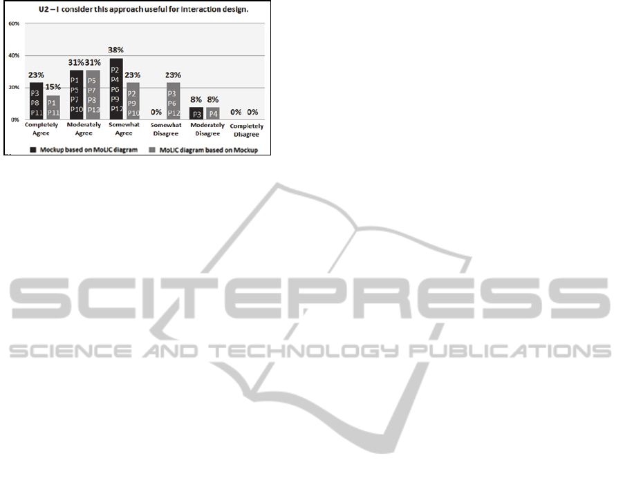
Figure 8: Answers to U2 – I consider this a useful
approach for interaction design.
approach facilitated interaction design”, we find
that, for the approach of creating the MoLIC
diagram based on mockups:
“MoLIC helps to understand concepts and it can help
before the construction of the mockup in order to prevent
waste of time to correct design errors” (P3)
“I find it easier to build the mockups based on the
MoLIC diagram, than the reverse process” (P6)
Conversely, for the approach of creating the
mockups based on the MoLIC diagram, we
highlight:
“The approach facilitated the design of the
interaction, since the mockups’ elements were described in
the diagram. Thus, it was not necessary to think a lot
about the mockups” (P4)
“MoLIC is easy to understand, but I believe that in the
case of a really big Project, the effort to create a diagram
will be much higher than with other design options” (P5)
In summary, although some participants found that
MoLIC diagrams were not so easy to build, most
participants considered the MoLIC diagrams useful
both for understanding the interaction design (i.e.,
valuable as an epistemic tool) and as a basis for
creating mockups. Moreover, considering the
number of defects found, our study also provided
indications of the effectiveness of the approach of
creating mockups based on MoLIC diagrams, but
not the reverse.
5 CONCLUDING REMARKS
This paper presented an empirical study regarding
the joint use of MoLIC diagrams and mockups to
evaluate the combined use the artifacts from the
point of view of undergraduate and graduate
students. The results showed different defect types
identified in MoLIC interaction diagrams and
mockups. We noticed that the highest occurence of
defects happened in the mapping from mockups onto
interaction diagrams. The results also indicates that
the approach of creating mockups based on MoLIC
diagrams is more useful for providing understanding
about the interaction and interface during HCI
design.
In any case, the large number of defects in
MoLIC diagrams highlighted the need of assess the
quality of these artefacts. We are currently
developing an inspection technique to help detect
and correct defects in MoLIC interaction diagrams
in a systematic way and in early stages of the
development process, to achieve more consistent
interaction modelling. Furthermore, we argue that
interaction modeling, along with the mockups, gives
the designer a clearer view of how the user interface
will present the system and how the communication
between the user and the user interface may occur.
As future work, we intend to execute a new
empirical study with experienced designers, both to
evaluate the cost/benefit of using MoLIC diagrams
and mockups in interaction and interface design, and
to compare MoLIC diagrams with other artifacts for
the development of interactive systems.
ACKNOWLEDGEMENTS
We would like to acknowledge the financial support
granted by CAPES (Foundation for the
Improvement of Highly Educated Personnel)
through process AEX 10932/14-3 and FAPEAM
(Foundation for Research Support of the Amazonas
State) through processes numbers: 062.00146/2012;
062.00600/2014; 062.00578/2014; and 01135/2011.
REFERENCES
Barbosa, S. D. J., da Silva, B. S., 2010. Human-Computer
Interaction (In Portuguese). Série SBC, Rio de Janeiro.
Basili, V., Rombach, H., 1988. The TAME Project:
Towards Improvement-Oriented Software
Environments. In IEEE Transactions on Software
Engineering, v. 14, pp. 758-773.
Davis, F., 1989. Perceived usefulness, perceived ease of
use, and user acceptance of information technology.
MIS Quarterly, v. 13, n. 3, p. 319 - 339.
Laitenberger, O., Dreyer, H. M., 1998. Evaluating the
usefulness and the ease of use of a web-based
inspection data collection tool. In Proc. of the 5th Int.
Symposium on Software Metrics, 122.
Lopes, A. C., Marques, A. B., Barbosa, S. D. J., Conte, T.
Evaluating HCI Design with Interaction Modeling and
Mockups. Report Number 0003, (2015). Available
at: http://uses.icomp.ufam.edu.br/
Luna, E. R., Panach, J. I., Grigera, J., Rossi, G., Pastor, O.,
2010. Incorporating usability requirements in a
ICEIS2015-17thInternationalConferenceonEnterpriseInformationSystems
86

test/model-driven web engineering approach. In
Journal of Web Engineering, 132 - 156.
Paula, M. G., Barbosa, S. D. J., Lucena, C. J. P., 2003.
Relating Human-Computer Interaction and Software
Engineering Concerns: Towards Extending UML
Through an Interaction Modeling Language. In
Workshop proc.: Closing the Gaps: Software
Engineering and Human-Computer Interaction, 40-46.
Preece, J., Rogers, Y., & Sharp, H., 2002. Interaction
design: Beyond human-computer interaction. New
York, NY: John Wiley & Sons.
Puerta, A. R., 1997. A model-based interface development
environment. IEEE Software, v. 14, n. 4, 40-47.
De Souza, C. S., 2005. The Semiotic Engineering of
Human-Computer Interaction. The MIT Press.
Sangiorgi, U. B., Barbosa, S. D. J., 2009. MoLIC
Designer: towards computational support to hci design
with MoLIC. In Symposium on Engineering
Interactive Computing Systems, p. 303.
Shull, F., Carver, J., Travassos, G. H., 2001. An empirical
methodology for introducing software processes. In
Proc. of 9th ACM SIGSOFT Int. Symposium on
Foundations of software engineering, p. 288 - 296.
Travassos, G. H., Shull, F., Carver, J., 2001 Working with
UML: A Software Design Process Based on
Inspections for the Unified Modeling Language.
Advances in Computer, Vol. 54, 35 – 98.
Venkatesh, V., Morris, M.G., Davis, G.B., et al., 2003.
User acceptance of information technology: Toward a
unified view. MIS Quarterly, v. 27, n. 3, pp. 425-478.
EvaluatingHCIDesignwithInteractionModelingandMockups-ACaseStudy
87
