
A Systematic Method for Architecture Recovery
Fritz Solms
Department of Computer Science, University of Pretoria, Pretoria, South Africa
Keywords:
Architecture Recovery, Architectural Tactics, Architectural Patterns, Architecture Description.
Abstract:
Software architecture recovery aims to reverse engineer a software architecture description from the system ar-
tifacts (e.g. source code) in order to facilitate software architecture analysis, improvement and control. Whilst
there are a number of software architecture recovery methods, none of the current methods focus purely on
those aspects of a system which address non-functional requirements. This paper introduces the Systematic
Method for Software Architecture Recovery (SyMAR). SyMAR is an inspection method used to recover a
software architecture description consistent with the view of a software architecture providing a specification
of a software infrastructure addressing non-functional requirements within which application functionality
addressing functional requirements can be deployed and executed. The method has been applied to a num-
ber of industrial architecture recovery projects. This paper discusses the experiences from these projects and
illustrates the method using one of these projects as a case study.
1 INTRODUCTION
Ongoing system maintenance often leads to architec-
tural drift and erosion (de Silva and Balasubrama-
niam, 2012) resulting in an increase in system com-
plexity, maintenance costs and architectural failures
(Roy and Graham, 2008; de Silva and Balasubrama-
niam, 2012). Furthermore, a lack of an authoritative
understanding of the software architecture makes it
difficult to analyze the causes of architectural con-
cerns and to effectively re-architect aspects of the
system to address such concerns. At this point it is
often advisable to recover the software architecture
of the system. Software Architecture Recovery in-
volves extraction of relevant information, abstraction
and description (Tilleyet al., 1994) resulting in a com-
plete or partial description of the software architecture
(Duenas et al., 1998).
Common challenges around software architecture
recovery include the size and heterogeneity of the
code bulk and that architectural abstractions are not
explicit at source level (Ducasse and Pollet, 2009).
Abstractions required for an architectural descrip-
tion include the identification of architectural pat-
terns or styles, architectural tactics and the concepts
and constraints a software architecture introduces for
the specification of application components (Solms,
2012). Here an architectural style or pattern is de-
fined as the structural organization of components
and connectors, with constraints on how they can be
combined (Shaw and Garlan, 1996). An architec-
tural tactic refers to a reusable technique used to con-
cretely address quality requirements (Rozanski and
Woods, 2011). In addition, a software architecture
may specify concepts and constraints within which
application functionality is to be developed (Solms,
2012). For example, using either stateful components
as in CORBA, Java-EE, stateless services Services
Oriented Architectures or pure functions as in Map-
Reduce based architectures affects the ease of reuse
(Erl, 2005), parallelization (Hinsen, 2009) and other
qualities.
Efforts to automate the recovery of aspects of the
architecture from source (Sartipi, 2003; Eisenbarth
et al., 2003; Hamdouni et al., 2010) are able to extract
component-connector views, generate message traces
across components and perform clustering into higher
level components or features. They are, however, not
in a position to perform abstractions into architectural
patterns and tactics. Nor are these methods able to
abstract application code into the concepts and con-
straints within which they are developed or even to
distinguish between aspects of the code which address
non-functional requirements (i.e. architecturally sig-
nificant code (Solms, 2012)) and those implementing
application functionality. Here application function-
ality refers to primary functional requirements around
what the processes the system needs to execute to
provide the user the functionality they require. Non-
functional requirements, on the other hand, refer to
system or service qualities like performance, scalabil-
ity, reliability, auditability, security, integrability and
215
Solms F..
A Systematic Method for Architecture Recovery.
DOI: 10.5220/0005383302150222
In Proceedings of the 10th International Conference on Evaluation of Novel Approaches to Software Engineering (ENASE-2015), pages 215-222
ISBN: 978-989-758-100-7
Copyright
c
2015 SCITEPRESS (Science and Technology Publications, Lda.)

so on. The non-functional requirements may give rise
to secondary functional requirements, i.e. functional-
ity which the system must provide in order to address
the non functional requirements. The latter fall within
the scope of software architecture as the concern is
still to address the non-functionalrequirements for the
system.
Manual processing of the entire code bulk is usu-
ally not feasible for large systems. However, a large
proportion of the bulk commonly implements ap-
plication functionality and provides little informa-
tion about the software architecture. This paper
presents a tool-assisted manual inspection method,
the Systematic Method for software Architecture Re-
covery (SyMAR), for recovering a software architec-
ture which requires that only a small proportion of
the code bulk needs to be analyzed. The output is
a software architecture description which, for each
level of granularity,specifies the architectural compo-
nents addressing infrastructural concerns, the infras-
tructure between these components (commonly in the
form of an architectural pattern), the tactics used to
concretely address quality requirements and the con-
cepts and constraints the software architecture intro-
duces for application development. The method has
been applied to a number of large industrial software
architecture recovery projects. One of these projects
is discussed in this paper as a case study.
2 RELATED WORK
(Ducasse and Pollet, 2009)’s extensive review of
software architecture recovery methods provides a
taxonomy of methods based on inputs and outputs,
whether a process is top-down, bottom-up or hybrid,
the extend to which a process can be automated, and
whether the recovery includes conformance or quality
analysis.
Many approaches recover a software architecture
in the form of components, their interfaces and the
connectors between them (Tilley et al., 1994; Due-
nas et al., 1998; Gorton and Zhu, 2005; Buchgeher
and Weinreich, 2009). Lindvall and Muthig (Lindvall
and Muthig, 2008) developed the Software Architec-
ture Visualization and Evaluation (SAVE) tool which
can be used to reverse engineer a component and con-
nector view of the SA at differentlevels of granularity.
Benefits of component-connector based approaches
include that these can be largely automated (Tilley
et al., 1994; Sartipi, 2003; Eisenbarth et al., 2003;
Hamdouni et al., 2010) and that most Architecture
Description Languages (ADLs) are able to describe
a software architecture in terms of components and
connectors (Gardazi and Shahid, 2009).
Within component-connector approach a core
challenge is the grouping of identified components
into higher level architectural components. (Duenas
et al., 1998) have shown that statistical clustering
techniques can be used to assist with the identification
of such higher-level components whilst (Eisenbarth
et al., 2003) used information extracted from both
static and dynamic analyses of the system to derive
correspondences between features and computational
units using concept analysis. (Sora, 2013) also inves-
tigates automated component aggregations via clus-
tering algorithms. She found that a suitable similarity
metric could be constructed from direct and indirect
class coupling measures. A notable contribution is
the use of dependency orientation analysis to identify
the use of architectural layering. This approach could
be used to assist with the aggregation of architectural
components into higher level components. Further-
more the dependency analysis could be extended to
also detect architectural patterns other than the layer-
ing pattern (e.g. microkernel, blackboard, controller,
...).
(Pahl et al., 2007) introduced a description logic
based formalization of architectural patterns and tac-
tics which should make it easier for future architecture
recovery tools to identify these abstractions within
software systems.
Whilst ISO/IEC/IEEE 42010:2011captures a con-
sensus around the requirements for an architectural
description (Emery and Hilliard, 2009), it does not
prescribe the required content of such. It is well
known (Pinzger and Gall, 2002; van Heesch et al.,
2012) that the quality and efficiency of architecture
decision recovery is improved by recovering architec-
tural abstractions.
Yet only few Architecture Description Languages
(ADLs) (Gardazi and Shahid, 2009) can capture these
explicitly. This may contribute to the low adop-
tion rate of ADLs in industry (Gardazi and Shahid,
2009). Whilst some ADLs do support abstractions
in the form of architectural patterns, tactics are cur-
rently only explicitly supported by Aspect-Oriented
ADLs like AO-ADL (Pinto et al., 2011) where qual-
ity requirements are seen as cross cutting concerns
which are addressed through tactics implemented as
aspects.
3 SyMAR
The Systematic Method for software Architecture Re-
covery (SyMAR) guides software architects through
a manual recovery of a software architecture descrip-
ENASE2015-10thInternationalConferenceonEvaluationofNovelSoftwareApproachestoSoftwareEngineering
216
tion. The output is an ISO/ISEC/IEEE 42010 com-
pliant architectural description containing the archi-
tectural abstractions discussed in (Solms, 2012). The
method relies largely on request tracing to efficiently
extract architectural features from system slices.
<<structured>>
abstraction and description
identify architectural responsibilities for
level of granularity and abstract assign to
abstract architectural components
abstract infrastructure to architectural
style/pattern for component
map architectural components onto
framework components
abstract code addressing quality
requirements into tactics
abstract application components
into concepts and constraints for
application components
project out request trace views
for level of granularity
ACCV
RTVs
FMV
RAV
SV
TV
<<structured>>
preparation
documentation analysis
interviews
<<structured>>
extraction
request tracing
select component
[there are lower level architecturally significant components]
[there no more lower level architecturally significant components]
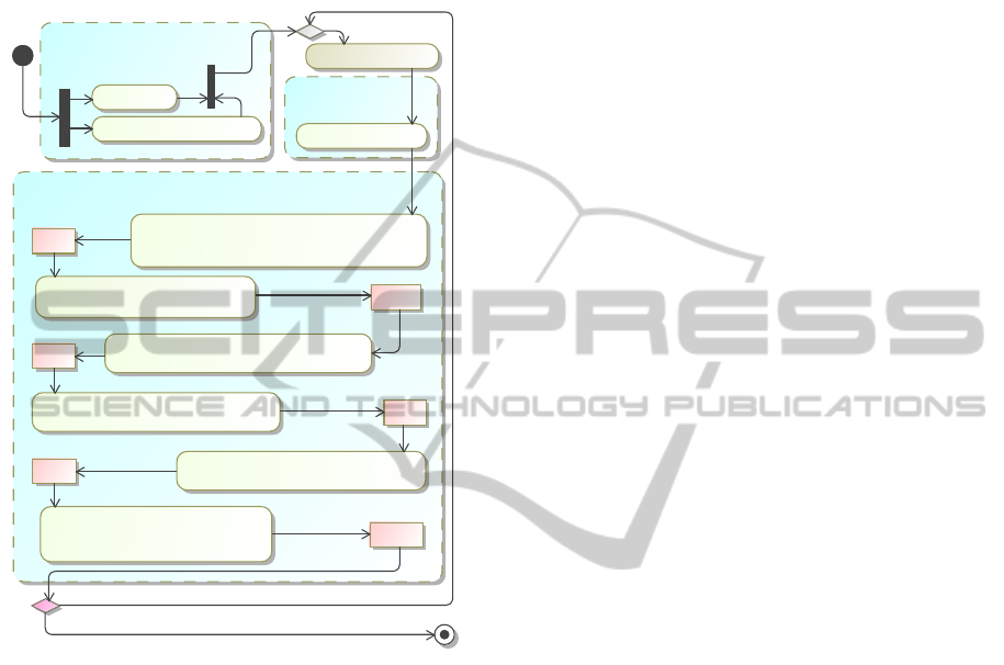
Figure 1: The systematic method for software architecture
recovery yielding, for each architecturally significant com-
ponent, one or more Request Trace Views (RTVs), a Re-
sponsibility Allocation View (RAV), a Structural View (SV),
a tactics view, Framework Mapping View (FMV) and an Ap-
plication Concepts and Constraints View (ACCV).
The method steps and generated views are shown
in Figure 1. For each architectural component one
projects out (1) one or more Request Trace Views
(RTVs) depicting the interaction across the first level
granularity sub-components, (2) a Responsibility Al-
location View (RAV) documenting the architectural
responsibilities which have been assigned to each
sub-component, (3) a Structural View (SV) showing
the connectivity between the components and the ab-
straction of the structure into a single architectural
pattern constraining the infrastructure for that compo-
nent, (4) a Tactics View (TV) showing the tactics ap-
plied at point cuts in order to address quality require-
ments, (5) a Framework Mapping View (FMV) show-
ing the mapping of architectural components onto
framework elements, and (6) an Application Concepts
and Constraints View (ACCV) describing any con-
cepts and constraints used for application components
hosted by that component.
3.1 Preparation
During the preparation step software architects obtain
access to the available resources and are briefed on the
scope and a high-level view of the system. Any avail-
able software architecture documentation is studied to
deepen the understanding, whilst keeping in mind that
the descriptions might be incorrect (out of date or mis-
represented) and incomplete.
The preparation step is followed by an iterative
recovery process which starts with the component
whose architecture is to be recovered (e.g. a system,
a module of a larger system). The process is repeated
for each architecturally significant sub-component,
e.g. a sub-component which addresses some infras-
tructural concerns like providing an access channel or
implementing a tactic like caching or load balancing
to address a quality requirement.
3.2 Extraction
The extraction phase is used to extract information
from the source code. It relies primarily on request
traces generated for different integration channels and
use cases. This can be automated using tracing or pro-
filing tools like InTrace or BTrace or any of the re-
verse modeling tools which support reverse engineer-
ing.
The number of request traces taken determines the
scope of the source code which is examined. Each re-
quest trace is for a particular user service and a par-
ticular access channel. The aim is to select a set of
use cases which is representative from an architec-
tural perspective. To this end representative use cases
which address different non-functional requirements,
are accessed through different access channels, and
integrate with different external systems are selected.
3.3 Abstraction
Extraction can be readily automated using any of
a number of request tracing or reverse engineering
tools. The core responsibilities of architecture re-
covery is that of identifying abstractions. It is these
abstractions which expose the architectural decisions
made in order to address non-functionalrequirements.
In SyMAR one starts with a manual inspection of
the request traces in order to abstract a) request traces
to the appropriate level of granularity, b) system ele-
ments into abstractions with assigned architectural re-
ASystematicMethodforArchitectureRecovery
217

sponsibilities, c) infrastructural constraints into archi-
tectural patterns, d) processes addressing quality re-
quirements into architectural tactics, and e) applica-
tion components into concepts and constraints within
which they are designed and implemented. These ab-
stractions as well as mappings of architectural respon-
sibilities onto framework components are captured in
the SyMAR views.
3.3.1 Abstracting Requests into Architectural
Responsibilities and Components
The first step is to identify and abstract architectural
responsibilities. To this end one analyzes service re-
quests within the request trace for the responsibili-
ties the services address. Responsibilities are then
grouped into higher level responsibility domains. The
highest level responsibilities are the responsibilities
for the current level of granularity. These are assigned
to abstract architectural components represented by
interfaces. The responsibility allocations for the cur-
rent level of granularity are captured within a Respon-
sibility Allocation View – see Figure 3 for an exam-
ple.
3.3.2 Request Trace Abstraction
The full request traces are generally very deep —
they typically include requests made to very low level
components. These need to be pruned to the current
level of granularity. This is done by including only
messages exchanged between the responsibility do-
mains identified in the previous step — see Section
3.3.1. All messages exchanged between components
within those responsibility domains are pruned.
3.3.3 Abstracting into Architectural Patterns
Once we have the request trace pruned to the current
level of granularity, we analyze the message exchange
pattern in order to determine the architectural pattern
used to constrain the infrastructure between the archi-
tectural components. This is done by comparing the
message exchange pattern to that of different archi-
tectural patterns.
For example, in the layered architectural pattern
synchronous requests are fed down through the lay-
ers and the corresponding responses ravel up the lay-
ers. In the case of the controller pattern, the requests
all disseminate from the controller itself whilst in
the case of the pipes and filters pattern the requests
are asynchronous requests along a pipeline. For the
blackboard pattern requests are made from various
components to the blackboard.
3.3.4 Architectural Tactics
Architectural tactics are used to concretely address
quality requirements. For example, resource reuse,
clustering, and caching are three examples of tactics
used to address scalability. Recovering the use of tac-
tics provides important information around how non-
functional requirements are addressed within a soft-
ware architecture.
Architectural tactics are commonly applied at in-
tegration channels, interception points, and at point-
cuts to which aspects are assigned. Furthermore,
frameworks commonly implement architectural tac-
tics in order to realize certain quality attributes. Thus,
in order to identify tactics one (a) investigates in-
terception points and connectors within the software
architecture for any tactics applied to them, (b) inves-
tigates the use of aspects, the tactics they implement
and the point cuts to which they are applied, and (c)
study frameworks used within the software architec-
ture for any tactics implemented by them.
3.3.5 Concepts and Constraints for Application
Components
A software architecture commonly introduces con-
cepts and constraints within which application com-
ponents addressing functional requirements are to be
developed. For example, a services-oriented architec-
ture introduces concepts like leaf services, composite
services, pipes and routers. Higher level services are
assembled from lower level services within a pipes
and filters paradigm. Java-EE, on the other hand, in-
troduces the concepts of enterprise beans (stateless
and stateful session beans, as well as message-driven
beans) and entities. Commonly application function-
ality is specified either within stateful objects or com-
ponents, stateless services which may still alter the
environment or pure functions receive an input and
compute a result without accessing (or modifying) the
environment.
Additionally a software architecture may specifies
some constraints which must be adhered to by appli-
cation components. For example, a service in SOA
must be stateless to facilitate composability of ser-
vices. and an enterprise bean in Java-EE may not cre-
ate any threads as this would interfere with the CPU
resource management of the application server.
4 AN INDUSTRIAL CASE STUDY
Towards the end of 2012, the author was requested to
reverse engineer the software architecture of a large
ENASE2015-10thInternationalConferenceonEvaluationofNovelSoftwareApproachestoSoftwareEngineering
218
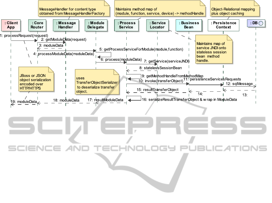
Figure 2: The request trace.
banking system used by corporate banking clients
across Africa. The system was originally devel-
oped within a vendor product which provided a SOA-
based software architecture meant to address the non-
functional requirements for the banking system as
well as generic application functionality which could
be customized and extended. The architecture was
however not able to provide the required levels of re-
liability and scalability resulting in a decade-long ar-
chitectural evolution to a Java-EE based architecture
which still retained many SOA aspects. The system
has around three million lines of code making a man-
ual recovery process with full code coverage imprac-
tical and prohibitively expensive.
The architecture recovery was done by a single
software architect. The resources made available for
the process were the lead architect and lead devel-
oper for the system to answer questions, the com-
plete source code of the system and any documen-
tation which was available for the system. The latter
was at a very high level and partially out of date. The
architecture recovery required 92 man hours.
4.1 Extraction
Request tracing was done using the InTrace
(http://mchr3k.github.io/org.intrace/) request tracing
tool which uses byte-code enrichment to insert call-
back methods to a tracer. The example request trace
in Figure 2 is pruned somewhat for the sake of com-
pactness. It shows how the trace exposes architec-
tural components used to demarshall and route ser-
vice requests as well as the persistence infrastructure.
Note that application logic is only contained in the
“business beans” and that all other components are
pure architectural components addressing infrastruc-
tural concerns and concerns around addressing non-
functional requirements.
The software architecture retained a number ser-
vices oriented elements. Requests are based on doc-
ument messages which have an envelope containing
metadata around the service requested (the service re-
quired and the module from which the service is re-
quired) as well as a message content containing the
core request data. These are separately demarshalled
within the routing and service adapter components.
Requests are taken through two levels of routing,
the first routing the request to the appropriate product
and the second routing the request to the appropriate
service as offered by a business logic component. In-
memory caches for product, component and service
handles are used to address performance and scala-
bility concerns. Note that in Java EE thread pooling
is achieved through object pooling of business logic
components whilst in SOA thread-pooling is at a ser-
vice level. The drift from a services-oriented software
architecture to a component based software architec-
ture has resulted in an infrastructure where service
handles are maintained as method handles and threads
are obtained through component lookup. This ap-
proach bypasses key elements of the Java-EE refer-
ence architecture.
Request tracing was done for both real-time re-
quests coming from different access channels, appli-
cation clients and mobile device clients and batch
requests submitted through message queues. These
traces were used to identify architectural components
traversed in the context of request processing.
ASystematicMethodforArchitectureRecovery
219
<<Responsibilty>>
Persist Domain Objects
<<Responsibilty>>
Encode Business Logic
<<Responsibilty>>
Map Domain Objects
to Database
<<Responsibilty>>
Demarshall Request
PersistenceContext
ApplicationAdapterClient Application
<<Responsibilty>>
Human adapter
<<Responsibilty>>
Route Request
ServiceBean
DatabaseRouter
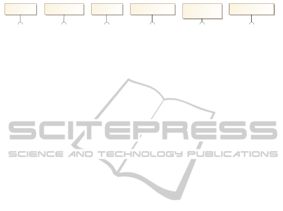
Figure 3: The responsibility allocation view for the first level of granularity.
4.2 Abstraction
Having a request trace exposing a slice through the
software system, we now need to separate applica-
tion functionality from architectural code addressing
non-functional requirements. The architectural code
is abstracted into architectural responsibilities, com-
ponents, patterns and tactics. The code implementing
application functionality is abstracted into concepts
and constraints within which application functional-
ity is specified. It is these abstractions which expose
the architectural decision made to address the quality
requirements for the system.
4.2.1 Architectural Responsibilities
In our case study we grouped the responsibilities of
the
CoreRouter
servlet and the
MessageHandler
utility class into that of demarshalling the re-
quest and assign that responsibility to the
ApplicationAdapter
abstraction. Similarly
the
ModuleDelegate
,
ProcessService
and
ServiceLocator
can be seen to collaborate to route
the request to the
BusinessBean
hosting the business
logic. The resultant identified responsibilities and
their allocation to abstract architectural components
is shown in Figure 3.
4.2.2 Abstracting Request Traces
In order to prune the request trace to the current level
of granularity we remove all messages sent within the
identified responsibility domains. This will remove
messages 2, 3, 5, 6, 7, 8, 9, 16 from the full re-
quest trace shown in Figure 2 resulting in a simpler
sequence diagram showing only the interactions rele-
vant for the current level of granularity.
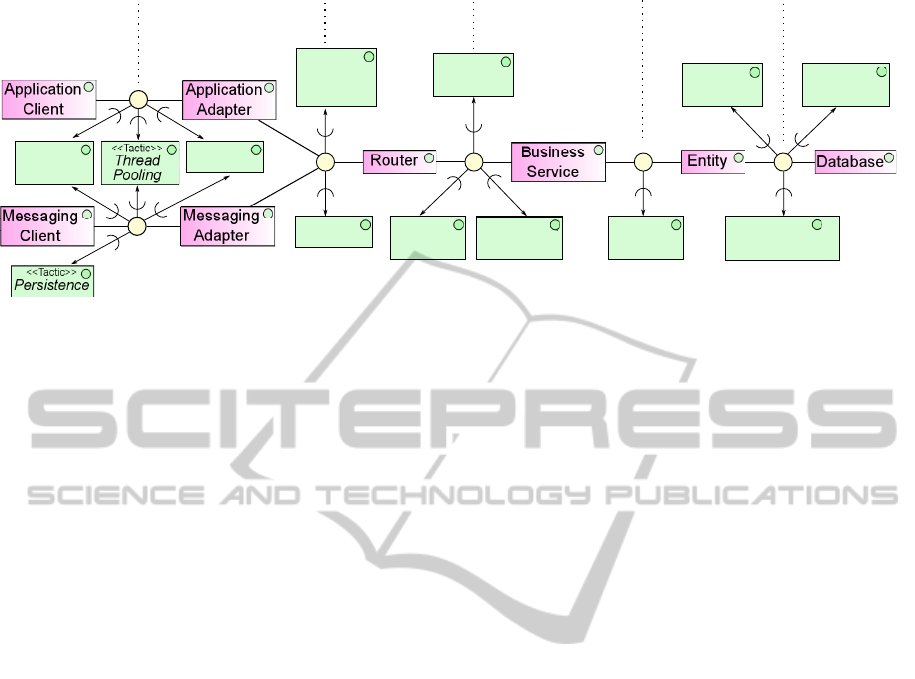
4.2.3 Architectural Patterns
In order to identify the structural pattern which con-
strains the infrastructure at the current level of granu-
larity, we analyze the message exchange patterns con-
tained in the pruned request trace from section 4.2.2.
The pruned request trace clearly shows that the ar-
chitectural components are arranged according to the
layering pattern as shown in Figure 4.
4.2.4 Architectural Tactics
Analyzing both, the tactics implemented in the frame-
works employed and any additional tactics applied
through interception resulted in the tactics shown Fig-
ure 4. The figure shows the tactics applied at connec-
tors using the AO-ADL notation (Pinto et al., 2011).
For example, load balancing, thread pooling and en-
cryption is applied to both, the connectors between
the application client and adapter and the messaging
client and adapter.
4.2.5 Concepts and Constraints for Application
Components
Being a Java-EE based architecture which evolved
from a services-oriented architecture, the applica-
tion functionality is specified within stateless ser-
vices packaged within business beans which are im-
plemented as stateless Java-EE session beans. Do-
main objects are implemented as JPA (Java Persis-
tence API) entities which are mapped onto a database
structure by a persistence context which in turn makes
use of an object-relational mapper. Higher-level ser-
vices are, however, not assembled from lower level
services within a pipes and filters paradigm (as is
common in a services-oriented architecture), but in-
stead using the process-manager or controller pattern
(Hohpe and WOOLF, 2004).
4.3 Lower Levels of Granularity
The process is repeated for lower levels of granular-
ity, taking one of the architectural components for the
current level of granularity as the new context. For
the case study it was found that three levels of gran-
ularity were sufficient, i.e. at the third level of granu-
larity lower level components were components pro-
vided by frameworks and not components developed
for this software architecture.
5 RESULTS
In addition to this case study, the method has been
applied to two other software architecture recovery
ENASE2015-10thInternationalConferenceonEvaluationofNovelSoftwareApproachestoSoftwareEngineering
220
Client Layer
Access Layer Routing
Layer
Services
Layer
Domain
Layer
Persistence
Layer
<<Tactic>>
Load
Balancing
<<Tactic>>
Encryption
<<Tactic>>
Encryption
<<Tactic>>
Runtime
Lookup
<<Tactic>>
Reference
Caching
<<Tactic>>
Object
Caching
<<Tactic>>
Connection
Pooling
<<Tactic>>
Object-Relational
Mapping
<<Tactic>>
Role-Based
Authorization
<<Tactic>>
Data Access
Authorization
<<Tactic>>
Binary-
Protocol
Mapping
Figure 4: The structural and tactics view for the first level of granularity using AO-ADL.
projects. The one was that of an integration infras-
tructure between front end systems offering a range
of products to users and the back-end systems host-
ing the business data and backend-services. The other
was that of reverse engineering an access channel for
mobile devices.
In the case of the first and third system, the soft-
ware architecture recovery required traversing about
5% of the source code. In the case of the integration
infrastructure there was a high level of infrastructure
resulting in about 30% of the source code having to
be traversed. This was due to the second project be-
ing largely an infrastructure project with no applica-
tion logic. The reason for having to cover only about
30% of the source code was the fact that many of the
adapters to the front and back-end systems were based
on a similar architecture and hence only representa-
tive adapters had to be analyzed. In all three projects it
was found that there was largely a clean separation be-
tween application components implementing applica-
tion functionality and architectural components pro-
viding infrastructure (connectivity, persistence, mar-
shalling/demarshalling) or implementing tactics like
load balancing, caching and role-based authorization.
The required levels of granularity depend on the com-
plexity of the architectural components, but in prac-
tice it is found that generally two to three levels of
granularity are sufficient for an architectural descrip-
tion which covers most of the architectural concerns.
The client reported that the architectural descrip-
tion did enable them to obtain deeper insights into
the software architecture which in turn enabled them
to apply a number of architectural improvements. It
is not clear yet whether the client will maintain the
software architecture description as the architecture
evolves into the future.
Core benefits of the method include that the
method scales well for large systems and that it pro-
vides an architectural description which does con-
tain useful architectural abstractions. However, the
method is not well suited for systems for which the in-
frastructural code is extensively intertwined with ap-
plication functionality. For such systems a lot more
code needs to be analyzed and the method is not able
to provide a useful architectural description. A fur-
ther limitation is that the method cannot be applied to
components for which the source code is not avail-
able. Particularly for enterprise systems it is quite
common to use vendor products which may impact
the realization of NFRs significantly. Finally, the
method assumes a level of homogeneity of the archi-
tecture across application functionality. For systems
for which this is not the case, a much larger propor-
tion of the code bulk would have to be covered.
6 CONCLUSIONS
The Systematic Method for Architecture Recovery is
able to provide useful architectural descriptions with
moderate effort for software systems which have a
relatively good separation between code implement-
ing application or business logic and infrastructural
code. The method is, however, not very useful for
systems for which the application code and infrastruc-
tural code are strongly interwoven.
Benefits of the method include that only a small
fraction of the system code needs to be analyzed,
that the method yields an ISO/IEC/IEEE 42010 com-
pliant architectural description with clean separation
between architectural and application components,
and that architectural abstractions are explicitly doc-
umented. This includes the identification of archi-
tectural components addressing architectural respon-
sibilities, structural patterns which constrain the in-
frastructure of the software system, tactics used to
address quality requirements and the concepts and
ASystematicMethodforArchitectureRecovery
221

constraints the architecture introduces for application
components.
Tracing tools can be used during the extraction
phase in order to automate the generation of raw re-
quest traces. The abstraction steps required a signif-
icant amount of manual effort. In future one may be
able to use formal or semi-formal specifications of ar-
chitectural patterns and tactics (Pahl et al., 2007) to
automate aspects of the abstraction phase.
The method was applied to enterprise systems.
Future work will study the usefulness of the method
for other types of software systems.
REFERENCES
Buchgeher, G. and Weinreich, R. (2009). Connecting archi-
tecture and implementation. In Meersman, R., Her-
rero, P., and Dillon, T., editors, On the Move to Mean-
ingful Internet Systems: OTM 2009 Workshops, vol-
ume 5872 of Lecture Notes in Computer Science,
pages 316–326. Springer Berlin Heidelberg.
de Silva, L. and Balasubramaniam, D. (2012). Control-
ling software architecture erosion: A survey. Journal
of Systems and Software, 85(1):132–151. Dynamic
Analysis and Testing of Embedded Software.
Ducasse, S. and Pollet, D. (2009). Software architecture re-
construction: A process-oriented taxonomy. Software
Engineering, IEEE Transactions on, 35(4):573–591.
Duenas, J., Lopes de Oliveira, W., and De la Puente, J.
(1998). Architecture recovery for software evolution.
In Software Maintenance and Reengineering, 1998.
Proceedings of the Second Euromicro Conference on,
pages 113–119.
Eisenbarth, T., Koschke, R., and Simon, D. (2003). Lo-
cating features in source code. Software Engineering,
IEEE Transactions on, 29(3):210–224.
Emery, D. and Hilliard, R. (2009). Every Architecture
Description Needs a Framework: Expressing Archi-
tecture Frameworks Using ISO/IEC 42010. In Joint
Working IEEE/IFIP Conference on Software Architec-
ture, 2009 & European Conference on Software Archi-
tecture. WICSA/ECSA 2009, pages 31–40. IEEE.
Erl, T. (2005). Service-Oriented Architecture (SOA): Con-
cepts, Technology, and Design. Prentice Hall PTRs.
Gardazi, S. and Shahid, A. (2009). Survey of software
architecture description and usage in software indus-
try of Pakistan. In Emerging Technologies, 2009.
ICET 2009. International Conference on, pages 395–
402.
Gorton, I. and Zhu, L. (2005). Tool support for just-in-time
architecture reconstruction and evaluation: an experi-
ence report. In Proceedings of the 27th international
conference on Software engineering, ICSE ’05, pages
514–523, New York, NY, USA. ACM.
Hamdouni, A.-E. E., Seriai, A., and Huchard, M. (2010).
Component-based architecture recovery from object
oriented systems via relational concept analysis. In
Kryszkiewicz, M. and Obiedkov, S. A., editors, CLA,
volume 672 of CEUR Workshop Proceedings, pages
259–270. CEUR-WS.org.
Hinsen, K. (2009). The promises of functional program-
ming. Computing in Science Engineering, 11(4):86–
90.
Hohpe, G. and WOOLF, B. (2004). Enterprise Integration
Patterns: Designing, Building, and Deploying Mes-
saging Solutions. The Addison-Wesley Signature Se-
ries. Prentice Hall.
Lindvall, M. and Muthig, D. (2008). Bridging the software
architecture gap. Computer, 41(6):98–101.
Pahl, C., Giesecke, S., and Hasselbring, W. (2007). An
Ontology-Based Approach for Modelling Architec-
tural Styles. In Oquendo, F., editor, Software Archi-
tecture, volume 4758, pages 60–75. Springer Berlin
Heidelberg, Berlin, Heidelberg.
Pinto, M., Fuentes, L., and Troya, J. M. (2011). Specifying
aspect-oriented architectures in AO-ADL. Informa-
tion and Software Technology, 53(11):1165–1182.
Pinzger, M. and Gall, H. (2002). Pattern-supported archi-
tecture recovery. In Proceedings of the 10th Interna-
tional Workshop on Program Comprehension, IWPC
’02, pages 53–, Washington, DC, USA. IEEE Com-
puter Society.
Roy, B. and Graham, T. (2008). An iterative framework for
software architecture recovery: An experience report.
In Morrison, R., Balasubramaniam, D., and Falkner,
K., editors, Software Architecture, volume 5292 of
Lecture Notes in Computer Science, pages 210–224.
Springer Berlin Heidelberg.
Rozanski, N. and Woods, E. (2011). Software Systems
Architecture: Working with Stakeholders Using View-
points and Perspectives. Pearson Education.
Sartipi, K. (2003). Software architecture recovery based
on pattern matching. In Software Maintenance, 2003.
ICSM 2003. Proceedings. International Conference
on, pages 293–296.
Shaw, M. and Garlan, D. (1996). Software Architecture:
Perspectives on an Emerging Discipline. Prentice-
Hall, Inc., Upper Saddle River, NJ, USA.
Solms, F. (2012). What is software architecture? In Pro-
ceedings of the South African Institute for Computer
Scientists and Information Technologists Conference,
SAICSIT ’12, pages 363–373, New York, NY, USA.
ACM.
Sora, I. (2013). Software architecture reconstruction
through clustering: Finding the right similarity fac-
tors. In Proceedings of the 1st International Work-
shop in Software Evolution and Modernization (SEM
2013), pages 45–54. SciTePress.
Tilley, S. R., Wong, K., Storey, M.-A. D., and Moller, H. A.
(1994). Programmable reverse engineering. Interna-
tional Journal of Software Engineering and Knowl-
edge Engineering, 4:501–520.
van Heesch, U., Avgeriou, P., Zdun, U., and Harrison, N.
(2012). The supportive effect of patterns in architec-
ture decision recovery: A controlled experiment. Sci-
ence of Computer Programming, 77(5):551–576.
ENASE2015-10thInternationalConferenceonEvaluationofNovelSoftwareApproachestoSoftwareEngineering
222
